

pre-exponential factor
AREaverage relative error
Bbutadiene
BETBrunauer–Emmett–Teller
DEAdiethylamine
EHDShydrodesulfurization activation energy, J/mol
FSmolar flow rate of solvent (n-hexane), mol/s
FTHmolar flow rate of thiophene, mol/s
FTH0molar flow rate of thiophene at the inlet of the reactor, mol/s
HDShydrodesulfurization
H2hydrogen
H2Shydrogen sulfide
KTHadsorption constant of thiophene, bar−1
adsorption constant of hydrogen, bar−1
adsorption constant of hydrogen sulfide, bar−1
Kiadsorption constant of component i, bar−1
kreaction rate constant, mol/min kg
LHSVliquid hourly space velocity, h−1
mcatcatalyst weight, g
pTHpartial pressure of thiophene, bar
partial pressure of hydrogen, bar
partial pressure of hydrogen sulfide, bar
rreaction rate, mol/min kg
Rgas constant
R2coefficient of determination
Ssolvent, e.g., hexane
SEEobjective function
Ttemperature
THthiophene
xTHthiophene conversion
Δsulfur vacancies
adsorption enthalpy of component i
θadsorption sites
1 Introduction
Hydrodesulfurization (HDS) has received much attention in recent years due to environmental and clean-fuel legislation [1]. This process aims to remove the sulfur-containing molecules that are present in the petroleum fractions. The sulfur-based compounds are hydrodesulfurized through various reaction routes, such as the direct desulfurization and the hydrogenation (HYD) followed by desulfurization. The high reactivity molecules, such as thiophene (TH) and benzothiophene, are mainly hydrodesulfurized via direct desulfurization [2]. The catalytic HYD of sulfur-containing molecules to hydrocarbons and hydrogen sulfide (H2S) has been intensively studied in the past decades [3,4]. The choice of the catalyst depends mainly on the required HDS conversion and the characteristics of the processed feedstock. The metal sulfide catalyst, in particular sulfided form of molybdenum-based catalysts, has been used as HDS catalysts for many years [5,6]. The typical HDS catalysts containing nickel and/or cobalt as a promoter were deposited on the high surface area carriers such as γ-Al2O3 and SiO2Al2O3 [7,8].
Supported cobalt–molybdenum (namely, CoMo) and nickel–molybdenum (NiMo) were comprehensively studied lately. CoMo can be considered as a promising catalyst for lighter fractions, whereas NiMo can be regarded as more active toward heavier fractions or deep HDS, being less sensitive to amines than the Mo and CoMo catalysts [9,10]. A comparative study of both catalysts was done [11]. Our study confirmed the dependency of the catalyst activity on feed.
Many different supports have been tested and many combinations were investigated. However, the typical support for commercial hydrotreating catalysts remains γ-Al2O3. The important features of alumina include their good mechanical and textural properties and their ability to provide high dispersion of the active metals [12,13]. The support material enhances the catalytic properties, whereas the surface orientation of alumina affects the catalytic functionality, such as activity toward HDS [14,15].
The effect of promoters on catalytic activity in the hydrotreating reactions has been widely investigated. The role of the promoter is to enhance the catalyst activity toward the increasing of the conversion and improving the reactivity of the compounds that are difficult to be removed. The usual promoters for HDS reaction are Ni and Co, whereas tungsten was also found to be active for hydrotreating [1,16].
The increasing demand to lower the sulfur levels in fuels leads to the motivation for the improvement of the current hydrotreating catalysts and the development of new materials. The additives and stabilizers (e.g., phosphorus and boron) may either change the HDS chemistry or improve the promoter atom distribution. During the last decade, phosphorus addition became the favored option as a stabilizer during the synthesis of hydrotreating catalysts. The effect of phosphorus addition on NiMo- and CoMo-supported materials was studied and some interesting findings were revealed. The increased catalytic activity is attributed to the dispersion of the active compound and increased Brønsted acidity [17,18]. The presence of phosphorus can decrease the coke formation, hence increasing the HDS activity [19,20]. The boron addition on NiMo/γ-Al2O3 was reported to increase the catalyst acidity and to improve the hydrocracking activity [21,22].
The continuous requirements for cleaner fuels indicate a better design and the formulation of new catalysts as well as the development of new active phases or supports. An option is to modify alumina support with different oxides. The metal oxides such as TiO2, ZrO2, and SiO2 are used for this purpose, having an important contribution for the HDS reaction [23–25]. Carbon as a support material was the subject of many studies and its positive role in HDS activity was detected [26–28]. Mesoporous materials like MCM-41 (Mobil Composition of Matter No. 41) are estimated to develop a better activity for deep HDS [29,30], whereas the zeolite materials (e.g., type Y, X) were found to have a significant effect on the HDS activity [31–33].
Promising efforts have been directed toward the TH HDS activity over trimetallic Co–Mo–Ni–supported catalysts. Few studies investigate trimetallic Co–Mo–Ni catalysts supported on Al2O3 and TiO2Al2O3 [34,35]. The comparative study with the commercial Co–Mo–Ni/Al2O3 shows the superior HDS activity for homemade catalysts [34]. Low titania loading in the support composition enhances the HDS activity, being considered as promising supports for Mo-based catalysts in TH HDS and deep HDS processes [34].
Because of the lack of studies of TH HDS over trimetallic Mo–Co–Ni-supported catalysts, the objective of the present work was to investigate the activity of the Mo–Co–Ni/γ-Al2O3 catalyst for TH HDS. Kinetics is also studied and the obtained results are compared with the experimental data.
2 Experimental section
2.1 Catalysts synthesis
The pore volume impregnation method was used to synthesize the Mo–Co–Ni/γ-Al2O3 catalyst. All precursor salts for each of the loaded metals were heptamolybdate tetrahydrate, cobalt (II) nitrate hexahydrate, and nickel (II) nitrate hexahydrate (Sigma–Aldrich). An amount of 14.18 g molybdenum precursor dissolved in deionized water was first impregnated. The water volume was precisely measured for the pore volume of the material to be impregnated. After the impregnation of molybdenum salt, the sample was dried at 160 °C and calcined at 450 °C for 6 h. The multiple impregnation steps were used to prepare the trimetallic Mo–Co–Ni/γ-Al2O3 catalyst. In the next step, the aqueous solution of 6.62 g cobalt salt was impregnated on the calcined Mo/γ-Al2O3, followed by drying and calcination under the same conditions. An amount of 6.64 g nickel precursor was subsequently loaded and the final catalyst was dried and calcined as previously mentioned. The concentration of precursors was calculated according to the desired metal content.
The abbreviation of the prepared Mo–Co–Ni/γ-Al2O3 catalyst given in this study is related to the impregnation sequences of the metals onto the support.
The commercial refinery catalysts usually contain roughly 10–15 wt % molybdenum, whereas cobalt and nickel loadings vary between 2 and 5 wt %. Because the presence of both Ni and Co metals in the Mo/γ-Al2O3 catalyst influences positively the activity and they act as promoters in the HDS reaction, appropriate concentrations are loaded for our homemade catalyst. The Mo–Co–Ni/γ-Al2O3 sample synthesized in our study has similar composition as the commercial refinery catalyst. Taking into account that the alumina support impregnated with various metals (e.g., Co, Mo, Ni, and V) is widely involved in hydrocracking processes [36,37], the scope of our study was to investigate whether the Mo–Co–Ni/γ-Al2O3 catalyst is active for HDS.
The metal loadings were kept constant (by mass) at about 11.5% Mo, 2% Co, and 2% Ni (determined by atomic absorption with Varian AA240FS). An amount of 90 cm3 alumina (cylindrical shape with the average size of 1 mm) was used as a support material. Alumina support (with Brunauer–Emmett–Teller [BET] surface area of 412 m2/g) was calcined at 550 °C for 6 h.
2.2 Catalyst characterization
Textural characteristics of the sample were measured by BET analysis on an Autosorb 1 Quantacrome instrument at liquid nitrogen temperature. Before the experiment, an amount of 30 mg catalyst was degassed at 300 °C for 4 h. The specific surface area (SBET) was determined by the multipoint BET method in the linear portion of the adsorption–desorption isotherm.
The acidity of the catalyst and alumina support was determined by temperature-programmed desorption (TPD) of diethylamine (DEA). Thermogravimetric analysis was performed using a DuPont Instrument device Thermal Analyst 2000/2100 coupled with a module 951 Thermogravimetric Analyzer. Desorption of the DEA was carried out by heating the samples from 20 to 600 °C in nitrogen atmosphere at 10 °C/min.
2.3 Activity tests
Before the experiments, the catalyst was activated with a flow rate of 15 L/h hydrogen (H2) at 450 °C for 6 h. The activity measurements over the Mo–Co–Ni/γ-Al2O3 catalyst were carried out in a fixed bed flow reactor (length of 0.5 m, volume of 200 cm3) surrounded by an electrical furnace. An amount of 40 cm3 catalyst was loaded in the middle of the reactor.
The top and the bottom of the reactor were filled each with an amount of 80 cm3 inert glass beads with the average diameter of 1–2 mm. The temperature was measured by an automatic system using three thermocouples placed in the reactor jacket. The thermocouples located at the top and bottom of the reactor were used to measure the temperature of the inert glass zones, whereas the catalyst temperature was monitored by the third thermocouple inserted in the middle of the reactor. The feed liquid mixture of 0.6 wt % TH and 99.4 wt % n-hexane (used as model gasoline) was introduced into the reactor using a metering pump and vaporized, mixed with H2, and preheated to a desired temperature before entering into the reactor. The H2 to TH molar ratio of 60 was kept constant during the measurements.
The kinetic experiments were carried out at varied temperatures ranging from 200 to 275 °C, with the total pressure from 30 to 60 bar and liquid hourly space velocity (LHSV) between 1 and 4 h−1.
The temperature and pressure of the reaction system were adjusted to the set values. The first test was started at 200 °C, pressure of 30 bar, and LHSV of 1 h−1.
The obtained mixture was sent to the condenser. The effluent gas was cooled and the liquid product was removed in a separator vessel from gas. The resulted gases were sent to ventilation, whereas the liquid product was taken 40 min after the experiments began. The liquid was collected under stationary conditions and analyzed with a Varian 3800 gas chromatograph equipped with Agilent VF-5 ms capillary column. A mass spectrometer (Varian 4000) was coupled to the gas chromatograph. The used carrier gas for GC/MS analysis was He and the injector temperature was kept at 155 °C. The detected liquid product from the HDS reaction was TH.
The stability test was performed before the runs and the experimental details are presented in Section 3.2.
3 Results and discussions
3.1 Catalyst characterization
Texture properties of the catalyst were considered to be the determining factor for the catalytic stability and performance in hydrotreating. The adsorption–desorption isotherms and the pore-size distribution curves of the Mo–Co–Ni/γ-Al2O3 are presented in Figs. 1 and 2, respectively.
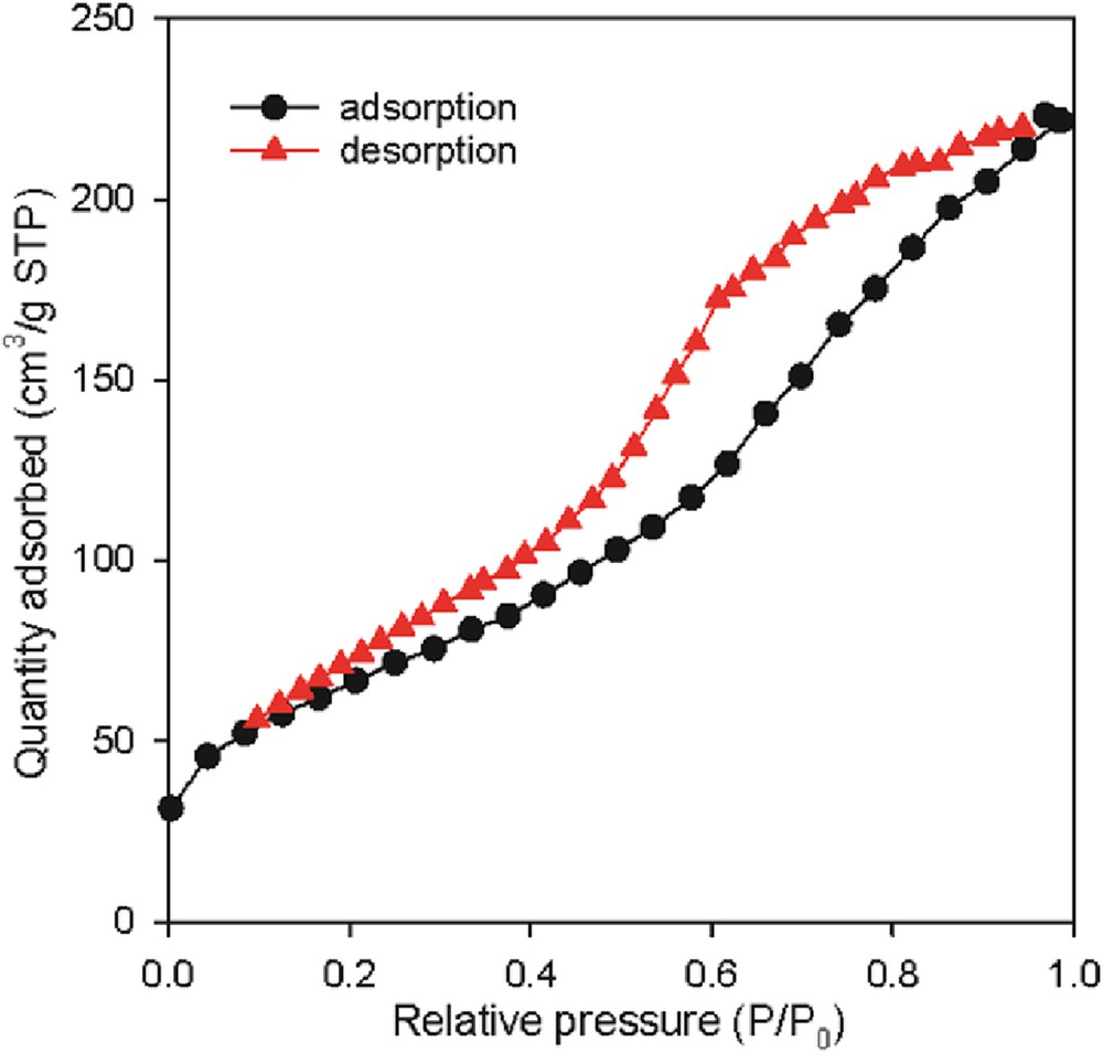
Adsorption–desorption isotherm of the fresh Mo–Co–Ni/γ-Al2O3 catalyst.
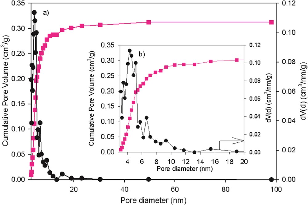
Pore-size distribution of the fresh Mo–Co–Ni/γ-Al2O3 catalyst.
The catalyst exhibits isotherms of classical IV type (Fig. 1), which are in agreement with Huang et al. [35]. The textural characteristics reported in Table 1 reveal large surface area, pore volume relatively large, and mesopore-size distribution between 3 and 20 nm, indicating good accessibility of the catalytic centers.
Textural properties of the fresh Mo–Co–Ni/γ-Al2O3 catalyst.
| Fresh catalyst | SBET, m2/g | Pore volume, cm3/g | Average pore diameter, nm |
| Mo–Co–Ni/γ-Al2O3 | 243 | 0.34 | 5.66 |
In the range of low relative pressure P/P0 (below 0.2), shown in Fig. 1, the nitrogen volume adsorbed by the catalyst is associated with a monolayer adsorption of nitrogen on the surface. An increase in the volume adsorbed and the presence of the hysteresis, specific for multilayer condensation of nitrogen in the catalyst pores, in conditions in which the relative pressure increases, are observed.
The textural properties (BET surface area, pore volume, and average pore diameter) of the sample are summarized in Table 1.
To determine the distribution of the strength of the acid centers exposed on the solid surface of the catalyst and support while undergoing temperature-programmed heating, the thermal desorption in the presence of DEA was performed.
Acidity of the alumina surface is defined through both Lewis and Brønsted acid sites. Lewis acid sites are coordinatively unsaturated centers, which are electron acceptors, whereas Brønsted acid sites are proton donors. The relationship between strengths and concentrations of surface acid sites and their catalytic activities has a significant role, being studied by many investigators [38].
The distribution of acid centers in terms of DEA weight loss with increase in temperature from 20 to 600 °C for fresh and spent Mo–Co–Ni/γ-Al2O3 catalysts, as well as for alumina support, is presented in Figs. 3–5. There are depicted three delimited zones (A, B, and C) for each sample, which are assigned to the weak, medium, and strong acidities. The weak acid centers are obtained in the first region, which ranges from 160 to 300 °C with DEA weight loss of 0.71 mg DEA for the fresh catalyst (Fig. 3), 0.43 mg DEA for the spent sample (Fig. 4), and a weight DEA loss of 0.46 mg DEA for the alumina support (Fig. 5). This reveals that spent catalyst presents a low amount of weak acid centers as compared to the fresh catalyst, whereas a significant decrease in the content of weak acid sites for the support is observed.
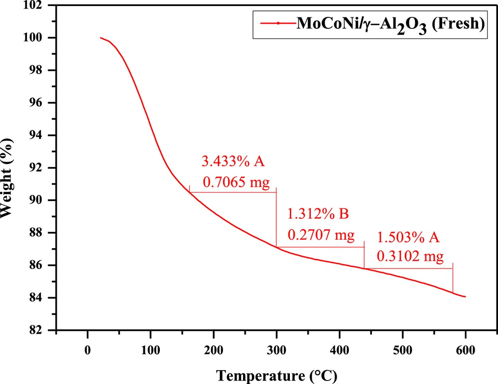
TPD of DEA (the loss of DEA with increase in temperature) for the fresh Mo–Co–Ni/γ-Al2O3 catalyst.
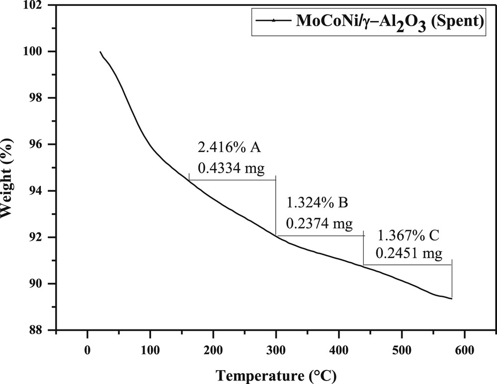
TPD of DEA for the spent Mo–Co–Ni/γ-Al2O3 catalyst (after runs).
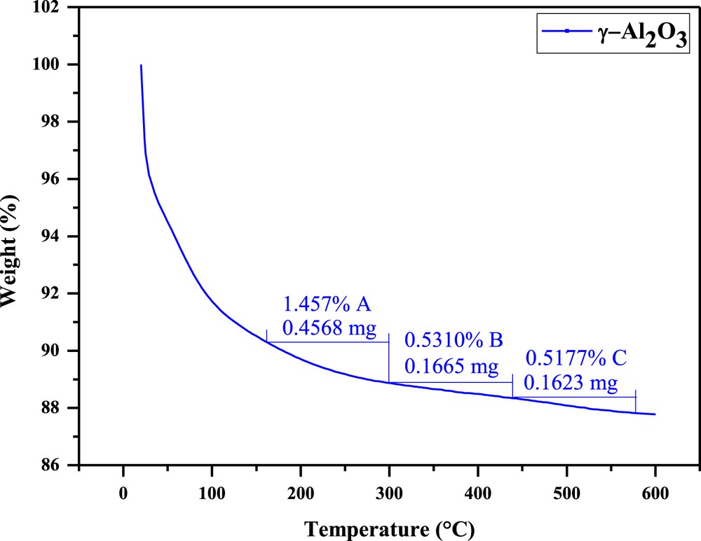
The loss of DEA with temperature for alumina support.
The considerable change in weak acid catalytic sites after runs indicates their contribution during the HDS reaction.
The second temperature ranged from 300 to 440 °C, corresponding to medium acid centers, revealing the weight loss of 0.27 mg DEA for the fresh Mo–Co–Ni-supported catalyst (Fig. 3) and 0.24 mg DEA for the spent catalyst. There is a relatively similar proportion of medium acid sites for both fresh and spent samples.
Above 440 °C, the C zone is assigned to the strong acid sites. A content of 1.5% for fresh and 1.4% for spent catalysts (Figs. 3 and 4) was found. Similar results indicate there is no change in strong acidity of the centers, being less involved in the HDS process. In the case of alumina, a loss of 0.16 mg DEA, corresponding to the amount of 0.52% strong sites (Fig. 5) was found.
We may conclude that the presence of the Mo, Co, and Ni enhances the total acidity of the catalyst and the acid properties of the centers influence the catalytic activity for the HDS reaction. Regarding the type of acid centers, comparing Figs. 3–5, both fresh and spent catalysts and support exhibit a high content of weak acid sites as compared to other types.
A quantitative estimation of acid sites was carried out. The values of acid strength (the loss with temperature of DEA in mEq/g catalyst) for fresh and spent Mo–Co–Ni/γ-Al2O3 catalysts and γ-Al2O3 are presented in Table 2. Highest content is mostly observed for weak acid centers for all materials, which are in agreement with the decrease in the weight loss of DEA during thermal desorption. The values of 0.47 mEq DEA/g for fresh and 0.33 mEq DEA/g for spent sample are revealed, whereas the amount of weak acid sites of support is about 0.2 mEq DEA/g, as depicted in Table 2. The results show the concentration of weak acid centers for support is about two times lower than catalysts. The acidity proportion in terms of medium and strong acid centers is approximately 2.3 times lower for alumina than the catalyst (e.g., 0.18 mEq DEA/g for the catalyst). The content of strong acid centers is about three times higher for the catalyst as compared to the alumina support (0.21 vs 0.07 mEq DEA/g), as shown in Table 2.
Acid strength distribution of Mo–Co–Ni/γ-Al2O3 and γ-Al2O3.
| Acidity (loss of DEA), mEq DEA/g | Mo–Co–Ni/γ-Al2O3 | γ-Al2O3 | |
| Fresh | Spent | ||
| Weak | 0.47 | 0.33 | 0.2 |
| Medium | 0.18 | 0.18 | 0.07 |
| Strong | 0.21 | 0.19 | 0.07 |
3.2 Catalytic evaluation
3.2.1 Catalyst stability
To investigate the catalyst stability, the sulfided Mo–Co–Ni/γ-Al2O3 catalyst was tested in the HDS of TH at 30 bar total pressure, temperature of 200 °C, and space velocity of 2 h−1. The results of HDS activity as a function of time on stream are shown in Fig. 6. The catalyst stability was examined for approximately 2 h. The increase in HDS conversion followed by its decrease was observed at the beginning of the experiment, revealing the presence of an induction period where the HDS conversion of 62% is achieved. A loss of activity was found in the first 30 min, followed by a relatively stable catalytic activity until the end of the experiment. The stability test is in agreement with Huang et al. [35], that reported about 5% loss in the catalytic activity during the first 50 h. After the 2 h stability test, the Mo–Co–Ni-based catalyst is used for kinetic study varying temperatures, pressures, and space velocities.
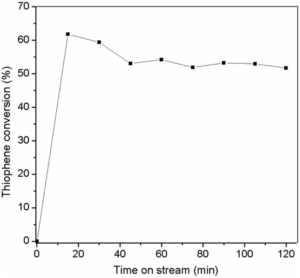
The activity as a function of time on stream over the Mo–Co–Ni/γ-Al2O3 catalyst at 200 °C, 30 bar, and LHSV of 2 h−1.
3.2.2 Effect of reaction temperature
Temperature is an important factor in the TH HDS. The behavior of TH conversion as a function of temperature by varying the space velocity from 1 to 4 h−1 is presented in Fig. 7. The results show that the activity increased with the temperature. The higher TH conversions were achieved at the temperatures of 250 and 275 °C, respectively, at P = 30 bar and LHSV = 1 h−1.
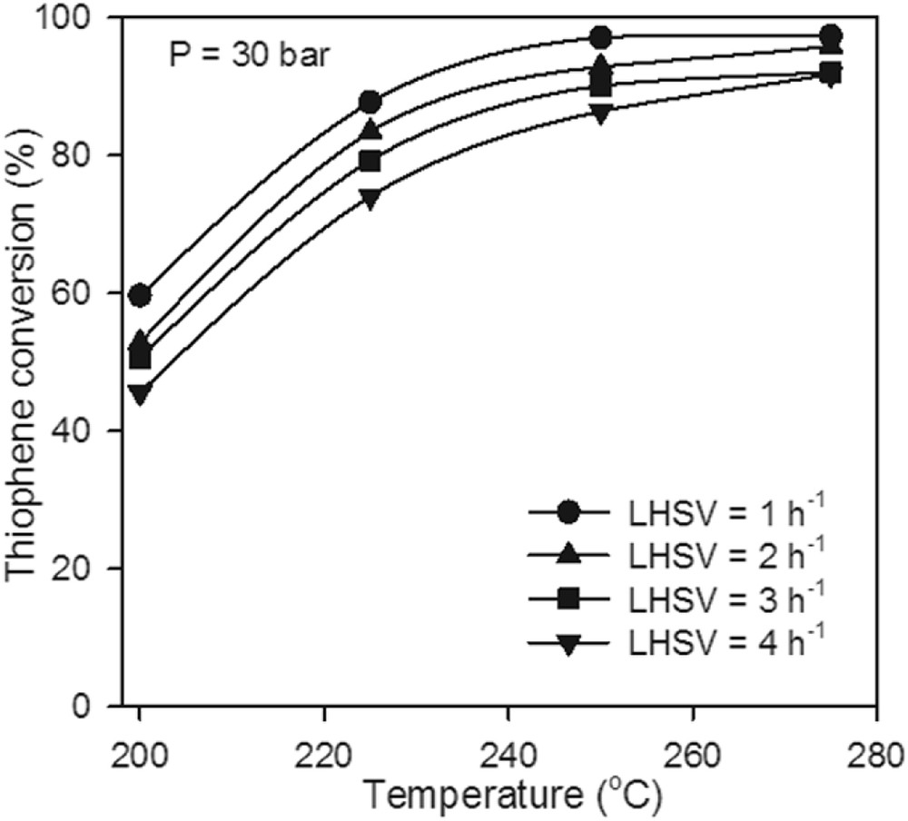
The effect of reaction temperature on TH conversion at P = 30 bar over the Mo–Co–Ni-supported catalyst.
3.2.3 Effect of pressure
The experiment revealed that the pressure and reaction temperature could significantly affect the reactivity of TH HDS. Fig. 8 shows the results of activity evaluation of TH HDS over the Mo–Co–Ni-supported catalyst by varying the reaction temperature and pressure. The observed TH conversion at 275 °C in the entire pressure range is considerably higher than at 200 °C in same pressure domain. Furthermore, the TH conversion increases with the pressure after a slope greater at lower temperatures. Thus, at 200 °C, the conversion of TH increases with the pressure from 52.88% to 72.21%.
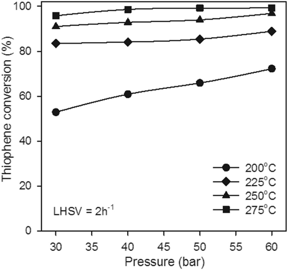
The effect of pressure on TH conversion at LHSV = 2 h−1 over the Mo–Co–Ni-supported catalyst.
3.2.4 Effect of LHSV
To evaluate the performance of the catalyst under working condition with higher extent of reaction, the reaction of TH HDS was conducted at higher pressure (up to 60 bar) and LHSV (max. of 4 h−1). Fig. 9 shows the change in the HDS activity of TH with the LHSV varying the pressure and the reaction temperature. At the chosen temperature of 250 °C (Fig. 9a), the LHSV has relatively little influence on the TH conversion in the pressure range of 30–60 bar, whereas a significant contribution of the LHSV was found at lower pressure.
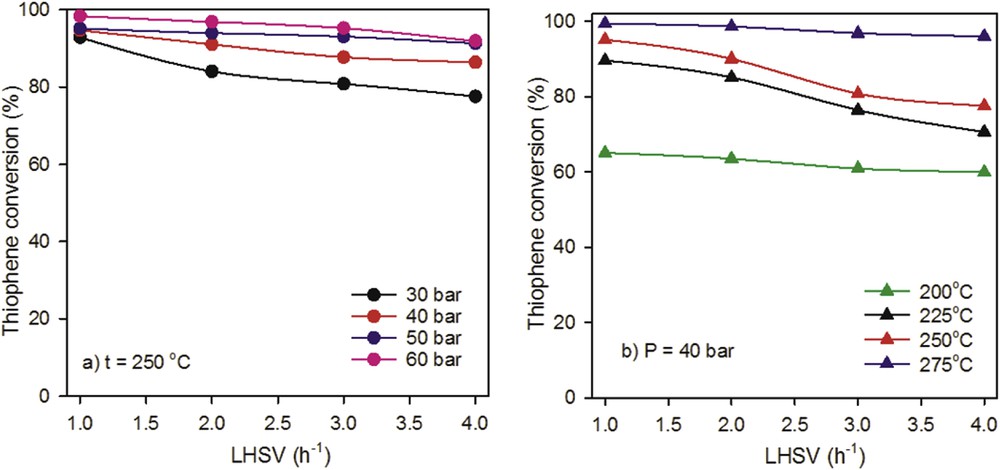
Effect of LHSV on TH conversion at (a) t = 250 °C, (b) P = 40 bar over the Mo–Co–Ni//γ-Al2O3 catalyst.
The effect of LHSV on the HDS conversion with the temperature is reported in Fig. 9b at target pressure. The results clearly show that the catalyst exhibits small variations in HDS activity with increasing LHSV, at higher (275 °C) and lower (200 °C) temperatures.
3.3 Kinetic analysis of HDS
Several mechanisms and reaction pathways for TH HDS have been reported over the past decades [39–43]. The hydrogenolysis of the CS bond preceded by HYD of the aromatic ring was investigated by Owens and Amberg [44], whereas Lipsch and Schuit [45] proposed that the CS bond was attacked by surface H2, leading to the formation of 1,3-butadiene.
Nowadays, the TH reaction pathway involves two parallel reaction ways, as shown in Fig. 10 [43]. In the first parallel pathway, known as HYD, the TH ring is hydrogenated. In the second pathway, known as hydrogenolysis, the TH ring can be broken due to attack by surface adsorbed H2 at the sulfur atom. Sulfur is further removed as H2S, leaving butadiene as the other product. Hydrogenolysis and HYD occur at different catalytic sites and this issue will be later studied. Furthermore, the studies demonstrated that H2S inhibits the TH HDS [46].
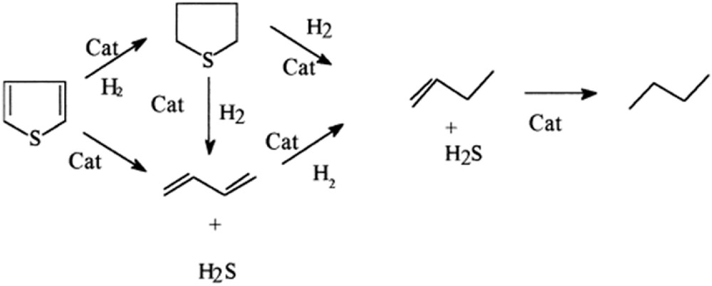
TH reaction pathways [43].
The kinetic tests performed by Van Parijs and Froment [47] suggested that the TH is first hydrodesulfurized to give 1-butene and isomers of 2-butene, followed by the secondary HYD of the butenes to butane. No butadiene was found in their experiments. Van Parijs and Froment proposed that TH hydrogenolysis should occur at σ sites, whereas the butene HYD should take place at τ sites [47].
According to the literature, the mechanism of TH HDS has not been fully understood yet. Consequently, in our study, we consider a simplified reaction network consisting of different steps [48]. The HDS reaction mechanism is presented in Fig. 11. The TH is hydrodesulfurized to give butadiene (B), which is subsequently hydrogenated to butene, followed by its HYD toward butane. The consecutive reaction scheme was generally adopted for the hydrogenolysis of TH into butadiene, butene, and butane, as given in Fig. 11.
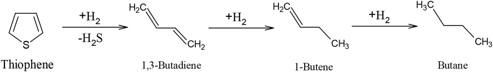
Reaction scheme of TH HDS.
Satterfield and Roberts [49] reported that the reaction proceeds first through butadiene intermediate, whereas C4 products consisting of butene and butane were further formed. The formation reaction of butane from butenes is very slow as compared to the butadiene conversion to butenes. Schuman and Shalit [50] have carried out kinetics studies on TH HDS and the results are in accord with the study of Satterfield and Roberts, concluding that butane formation reaction is not rapid as compared with the butene formation. On the one hand, the reaction rate for the HDS reaction is influenced by the sulfur content and the degree of substitution of the thiophenic ring [43,51]. The TH exhibits were proved to bring about the highest reactivity as compared to other sulfur-containing compounds [52].
On the other hand, it is well known that the structural changes in hydrocarbons increase with the increasing acidity of the catalysts. A carbocation mechanism is involved in hydroprocessing reactions. Both carbocations and free radicals participate in the overall mechanism of the hydroprocessing [53]. In the Mo–Co and Mo–Ni–based catalysts, molybdenum oxides exhibit an acid function, whereas Ni and Co have a dual hydrogenant–dehydrogenant function in hydroprocessing reactions.
TH and H2S adsorb on sulfur vacancies, denoted as Δ. H2 is subjected to the dissociative adsorption and adsorb on different vacancies (indicated as θ), as shown in Fig. 12 [48].
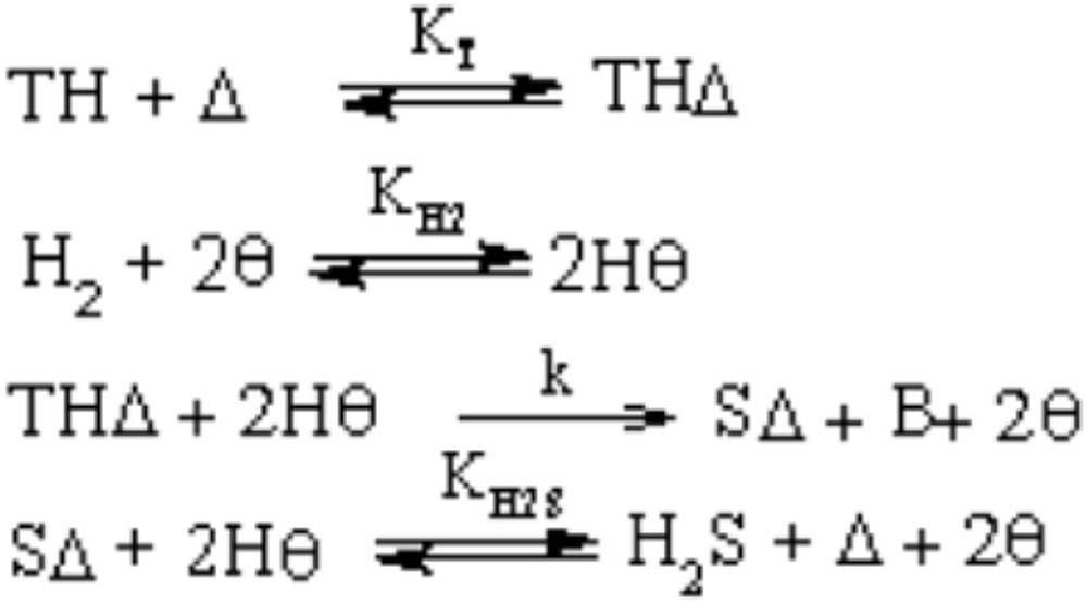
HDS reaction mechanism [48].
The rate-determining step is regarded as the surface reaction between the adsorbed TH and the adsorbed H atom; butadiene is formed [39,48], whereas the HYD of butadiene to butenes and butane is considered kinetically irrelevant [40].
The Langmuir–Hinshelwood mechanism proposed by Niemantsverdriet et al. [48] was used in this article to define the rate expression for TH HDS reaction. The form of the rate equation is represented by Eq. 1 [35,48]:
| (1) |
Arrhenius form is used to calculate the constant reaction kinetics. Arrhenius equation parameters, such as the activation energy (EHDS) and pre-exponential factor (A) are determined.
| (2) |
The temperature dependences of the rate constant and the equilibrium constants can be expressed as follows:
| (3) |
The design equation for a tubular reactor is given by Eq. 4, where FTH is the molar flow rate of TH, mcat is the mass of the catalyst in grams, and r is the reaction rate.
| (4) |
For any position in a flow system, FTH is defined according to Eq. 2, where FTH0 is molar flow rate of TH into the system and xTH is the TH conversion.
| (5) |
From Eqs. 4 and 5, the differential form of the design equation for a plug-flow reactor is written as
| (6) |
The molar fractions of TH, H2, and H2S are expressed in terms of the conversion of TH, as follows:
| (7) |
| (8) |
| (9) |
| (10) |
The average relative error (ARE) defined by Eq. 11 is equal to 4.6 (Table 2). The minor deviations of the TH conversion between the experimental measurements (xexp) and the model predictions (xcalc) for all runs reveal that the two-site Langmuir–Hinshelwood model describes well the reaction kinetics of TH HDS over the Mo–Co–Ni/γ-Al2O3 catalyst.
| (11) |
The pre-exponential factor, the TH activation energy, and the adsorption parameters for the different catalysts are presented in Table 3. The kinetic and adsorption parameters can be estimated from the experimental data.
Kinetic and adsorption parameters of HDS of TH over Mo–Co–Ni/γ-Al2O3.
| Parameter | Value |
| A, mol/min kg | 1500 |
| E, kJ/mol | 52 |
| K0TH, bar−1 | 8.42 |
| , bar−1 | 19.64 |
| , bar−1 | 52,210 |
| ΔHTH, J/mol | 189 |
| , J/mol | 878 |
| , J/mol | 930 |
| SSE | 1.98 × 10⁻² |
| R2 | 0.99 |
| ARE, % | 4.6 |
| Temperature range, °C | 200–275 |
The resulted activation energy of 52 kJ/mol in this work (Table 3) is close to that reported by Huang et al. [35] (65.8 kJ/mol), whereas the estimated values for the heat of adsorption of TH and H2S are 189 and 878 J/mol, respectively. The statistical parameter (R2), which defines the quality of the fits, is also shown in Table 3.
The adsorption parameter of H2 exceeds those of H2S and TH by 2–3 orders of magnitude (Table 3). The results show that the AREs are less than 5%, indicating the good accuracy of the model.
For the proposed mechanism where the TH and H2S adsorb on sulfur vacancies (Δ) and H2 undergoes dissociative adsorption and adsorbs on other vacancies (θ), the used expression was Langmuir–Hinshelwood. Good agreement between prediction and experimental data was obtained.
The linearity of the natural logarithm of the absorption constants of H2S, H2, and TH with the inverse of temperature, presented in Fig. 13, demonstrates the adequacy of the proposed model.
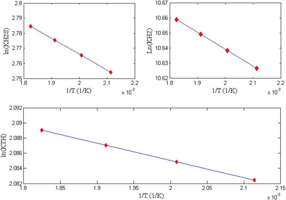
The natural logarithm function of the adsorption constants of H2S, H2, and TH (, , KTH) as function of 1/T.
Correlation between experimental data and model predictions for TH conversion is depicted in Fig. 14.
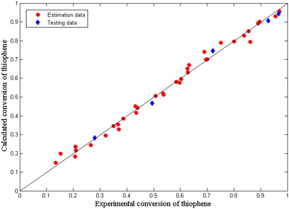
Calculated versus experimental TH conversion values.
As can be seen, the model errors are small for all performed experiments. Thus, the model satisfactorily predicts the TH HDS conversion and the measured data fitted well with the model. The proposed model can optimize laboratory procedures. It can be considered a tentative guide to the HDS research of supported Mo–Co–Ni-based catalysts.
4 Conclusions
In the present work, Mo–Co–Ni supported on γ-Al2O3 was prepared by the pore volume impregnation method. The multiple impregnation steps were used to prepare the trimetallic Mo–Co–Ni/γ-Al2O3 catalyst. The contents of 11.5% Mo, 2% Co, and 2% Ni were loaded on alumina support.
The homemade trimetallic catalyst was characterized before and after tests (fresh and spent catalysts). The determination of acid surface properties of fresh and spent catalysts, as well for the support material by thermal desorption of DEA with increase in temperature was studied. This study showed the content and type of acid sites in terms of weight loss of DEA at various temperature ranges. The weak, medium, and strong acidities were observed at various temperature ranges. The spent catalyst showed a low content of weak acid centers as compared to the fresh catalyst, assigned to the temperature range of 160–300 °C, whereas a significant decrease in the content of weak acid sites for the support was observed. The significant change in weak acid sites after runs may indicate their contribution for the HDS reaction.
The second temperature ranged from 300 to 440 °C corresponded to the medium acid centers and similar amounts for both fresh and spent samples were found.
The strong sites were observed above 440 °C and the appropriate content in strong acid centers was found. Overall, we may conclude that the presence of Mo, Co, and Ni enhances the total acidity of the catalyst and the acid properties of the centers influence the catalytic activity for the HDS reaction.
Nitrogen physisorption results showed a large surface area and a relatively large pore volume of the fresh trimetallic material, suggesting a good accessibility of the catalytic centers.
Stability tests performed as a function of time for 2 h show that the loss in the catalytic activity of the novel catalyst was about 4% during the first 30 min, but 40 min after the beginning of the test, almost no loss in the activity was observed.
Catalytic activity tests showed that the Mo–Co–Ni-supported material is active at higher temperature (275 °C) with increase in pressure for the space velocity of 2 h−1. The catalyst exhibits small variations in HDS activity with increasing LHSV, at higher (275 °C) and lower (200 °C) temperatures.
In this study, we proposed a kinetic model for TH HDS based on Langmuir–Hinshelwood theory, predicting an adequate TH conversion. The kinetic parameter values are close to those proposed for hydrotreating processes.
Acknowledgments
This study is collaboration among the Petroleum-Gas University of Ploiesti, National Institute for Research Development for Chemistry and Petrochemistry – ICECHIM, Bucharest, and Research Institute for Auxiliary Organic Products, Medias.