


 CC-BY 4.0
1. Introduction
Field-based observations, seismic reflection profiles, balanced and restored crustal-scale sections, as well as analogue and numerical models demonstrated the geometry and kinematics observed in contractional settings such as fold-and-thrust belts are controlled by various factors. These factors have been studied, such as the presence of pre-existing structures [e.g., Nilforoushan et al. 2013; Nabavi et al. 2020; Del Ventisette et al. 2021; Najafi et al. 2021; Shamszadeh et al. 2022a], basement morphology and thrust ramp dip angle [e.g., Maillot and Koyi 2006; Rosas et al. 2017; Caër et al. 2018; Ghosh et al. 2020], the depositional environment, mechanical stratigraphy (i.e. the mechanical properties, thickness of layers, and interface properties of rock units) [e.g., Cruz et al. 2008; Farzipour-Saein and Koyi 2014; Pla et al. 2019; Ito and Moore 2021], the presence of décollements (single and/or multiple) and their initial configurations [e.g., Sherkati et al. 2006; Stockmal et al. 2007; Graveleau et al. 2012; Nilforoushan et al. 2012; Ruh et al. 2012, 2013, 2017; Watkins et al. 2014; Ghanadian et al. 2017a, b; Li and Mitra 2017; Borderie et al. 2018; Derikvand et al. 2018, 2019; Heydarzadeh et al. 2020; Gu et al. 2021; Eslamirezaei et al. 2022; Mohammadrezaei et al. 2022], the basal slope and velocity [e.g., Rosas et al. 2017], the basal friction [e.g., Cotton and Koyi 2000; Costa and Vendeville 2002; Koyi and Maillot 2007], the angle of convergence [e.g., Casas et al. 2001; McClay et al. 2004; Leever et al. 2011; Barcos et al. 2016; Nabavi et al. 2017a, b, 2020], strain rate [e.g., Smit et al. 2003; Ruh et al. 2014], and syn-kinematic (syn-tectonic) surface processes (i.e. sedimentation and erosion) [e.g., Pichot and Nalpas 2009; Cruz et al. 2010, 2019; Wu and McClay 2011; Driehaus et al. 2014; Derikvand et al. 2019; Pla et al. 2019; Dal Zilio et al. 2020; Xu et al. 2021]. A class of fault-related folds is décollement folds, which are folding of more competent layers above a weak décollement without a ramp fault coring the uplift with a decreasing in displacement on a décollement [Mitra 2003; Fossen 2016; Nabavi and Fossen 2021]. A variety of thin-skinned fold-and-thrust belts (i.e. décollement-dominated interpretive structural style and where deformation restricted to the sedimentary cover above the décollement level) are developed associated with multiple décollements such as the Zagros fold-and-thrust belts [e.g., Sepehr and Cosgrove 2004; Sherkati et al. 2006; Vergés et al. 2011; Yosefnejad et al. 2017; Derikvand et al. 2018; Meng and Hodgetts 2019a; Shamszadeh et al. 2022b], the Jura Mountains [e.g., Schori et al. 2015], the Pyrenees [e.g., Koyi and Sans 2003], which exhibit low basal, intermediate and even upper friction related to lithology (salt, shale, marl) and/or overpressure conditions.
Many studies have already recognized that the density and thickness of décollements have played a significant role in the structural evolution and style, strain distribution and partitioning, controlling coupling and decoupling processes, and syn-kinematic processes in thin-skinned fold-and-thrust belts [e.g., Cotton and Koyi 2000; Koyi et al. 2000; Mitra 2003; Sherkati et al. 2005; Vergés et al. 2011; Ruh et al. 2012, 2013; Schori et al. 2015; Meng and Hodgetts 2019a, b; Gu et al. 2021; Nabavi and Fossen 2021; Sun et al. 2021; Xu et al. 2021]. Low-friction décollement is much weaker than any other layer in the rock sequences, so allowing material to flow at geologically high strain rates in response to normal and shear stresses of around 1 MPa. Moreover, portions dominated by folding are commonly underlain by a low-friction décollement and the flow of weak material into the cores of anticlinal structures may be inevitable for the evolution of décollement folds [e.g., Burberry et al. 2010; Cui et al. 2019].
Although previous studies have achieved an understanding of the role of décollements in the structural evolution of thin-skinned fold-and-thrust belts. This issue remains questionable, and numerical models provide an understanding of deformation patterns and structural styles. Proper interpretation of the structural evolution and structural style are essential to build the accurate understanding of the surface and subsurface geometry of structures. In this way, numerical modelling using discrete element method (DEM), as a particle-based method, provides means for simulating and tracking the spatial and temporal evolution of stress distribution, strain localization and sequential evolution of structures. It has been recognized that fold-and-thrust belts evolved in décollement-dominated way and exhibit wide range of structural styles, different fault-fold interactions, and associated fault-related folds, the mechanical conditions that contribute to these variations have not well to be understood.
This study makes use of a series of discrete element numerical models using the Itasca Particle Flow Code (PFC3D®, version 6,13, Itasca Consulting Group) to investigate the formation, development and evolution of thin-skinned fold-and-thrust belt comprising pre-kinematic low-frictional décollements , the number of décollements, thickness of décollements, the sequence of competent and less competent layers within the sedimentary cover sequence under an applied horizontal pressure and the amount of shortening. In this context, the present study aims to understand how the presence of low-friction multiple décollements influence the deformation style of thin-skinned fold-and-thrust belts. These mechanical properties have a direct influence on the deformation pattern of individual layers as well as the entire stratigraphic sequence.
Geological processes such as diagenesis, erosion, fluid flow, temperature, etc. are not considered. The primary reason for this approach is that we seek to isolate the effects of a few selected parameters in order to keep the analysis traceable. Besides, the numerical models can provide a powerful tool both to help interpret the structural style affected by décollements that may be poorly imaged on seismic profiles and previous models and to understand the kinematics and mechanics of fold-and-thrust belts which include more than a décollement. Finally, the modelling results of the present study are compared with natural examples, as well as analogue and numerical models.
2. The discrete element modelling method (DEM)
2.1. Basic principles
To develop an accurate understanding of the geometry of structures, the detailed analysis of structural evolution and structural style is needed. Numerical modelling using the Discrete Element Method (DEM) can simulate and monitor the spatial and temporal evolution of stress distribution as a particle-based approach. DEM, in except of time-consuming calibration of particle parameters to material properties, is an effective method to investigate the initiation, propagation, interaction and linkage, and evolution of folding, fracturing, and faulting in a practical manner involving deformation and large relative displacements.Many previous researches have used the DE-models and have been successfully produced realistic styles of geological and tectonic features such as normal faulting in layered sequences [e.g., Botter et al. 2014; Hardy 2019], décollement folding [e.g., Hardy and Finch 2005; Eslamirezaei et al. 2022], fault-bend folding [e.g., Benesh et al. 2007; Hughes et al. 2014], fault-propagation folding [e.g., Hardy and Finch 2006; Hughes and Shaw 2015], and fold-and-thrust belts [e.g., Burbidge and Braun 2002; Hardy et al. 2009; Morgan 2015; Meng and Hodgetts 2019a, b].
A series of DE-mechanical models, are applied for simulation of deformation of the rock layers in a shortening setting. In this approach that uses a time stepping, finite difference approach to solve Newton’s equations of motion, the rock mass is assumed to be composed of soft-circular, disk, or disc particles that interact in pairs as if bound by breakable elastic bonds (springs) and move relative to one another. These particles interact with elastic, gravitational, frictional and viscous forces under applied forces and displacement boundary (or wall) conditions. At each discrete time step, the particles are displaced to their new positions within the model by integrating their equations of motion using Newtonian laws and a velocity-Verlet-based numerical scheme, which is a numerical method used to integrate Newton’s equations of motion as this integrator strike a good balance between computational cost, stability, and accuracy [Verlet 1967]. The particle bonding is controlled by normal and shear bond stiffness, bond strength, and bond radius. In this regard, the normal and shear contact forces (Mohr–Coulomb criterion) are calculated between two overlapping or contacting particles using a rheological contact law. The bonds can be broken when the inter-particle forces exceed the bond strength. In this respect, slip can occur between particles. Thus, discontinuities and heterogeneities can form and evolve in response to changing stress condition and material properties [e.g., Cundall and Strack 1979; Hardy et al. 2009; Hughes et al. 2014; Morgan 2015; Smart et al. 2011; Hardy 2019; Meng and Hodgetts 2019a, b; Eslamirezaei et al. 2022].
2.2. Model setup
In the present study, we present a series of particle-based DE-models using the Itasca Particle Flow Code, named PFC3D® software package (vers3ion 6.13, Itasca Consulting Group, https://www.itascacg.com/software/pfc). PFC® was initially developed for describing mechanical behavior of material (soil or rocks) and allows much flexibility in simulations and is widely used among geologists as it allows to model large deformations. We created a regular initial model (Figure 1) consisting of 21403 spherical particles in the part of upper crust model with dimensions of 10 km length × 1 km width × 0.5 km thickness (x,y,z). The particles radii range from 25 to 41 m for both décollements and cover layers following the Gaussian distribution of particle size. The mechanically layered cover sequence consists of relatively competent layer and relatively less competent layers. The average rock density for all particles is about 3000 kg/m3. Particle stiffness (both shear and normal) were assigned with values of 1 × 10⁹, 0.5 × 10⁹, and 0.1 × 10⁹ N/m, respectively, for competent, less competent, and weak décollements, (Table 1). Inter-particle friction (μ) was assigned as 0.5 for cover layers, whereas 0 for décollements that are frictionless to ensure their low strength [e.g., Morgan 2015; Meng and Hodgetts 2019a]. All over, we examined different models based on changing variations included décollement number and thickness and the position and number of competent and less competent layers within the sedimentary cover. Colored layered within the cover sequence above and adjacent to décollements serve as strain markers during progressive deformation of the models and indicate contrast in material properties.
Initial design and boundary condition of discrete element models. Models are consisted of a basal décollement and adjacent layers of less competent and competent layers; middle and upper décollements will have added in the process of modelling. The fs = shearstress, fn = normalstress and b is particle bond.
Summary of material properties and parameters used in 3D DE-models
| Parameters | Décollements layers | Overburden | |
|---|---|---|---|
| Less competent layers | Competent layers | ||
| Particle radius (m) | 25–41 m | ||
| Particle Stiffness (N/m) | 0.1 × 10⁹ | 0.5 × 10⁹ | 1 × 10⁹ |
| Contact friction (μ) | 0 | 0.5 | |
| Tensile bond strength (N) | 0 | 2.5 × 10⁶ | 5 × 10⁶ |
| Average density (kg/m3) | 3000 kg/m3 | ||
Our experimental setup consists of a horizontal surface and four vertical model boundaries. All of these surfaces are defined in the models by rigid, frictional boundary walls (i.e. free-slip boundary conditions). Numerically, free surface boundary conditions are applied on the top model face, thus permitting self-consistent evolution of topography [Nabavi et al. 2020]. Acceleration due to gravity (9.81 m/s2) is imposed throughout the deformation as a body force. In all study models, a horizontal, vertical, compressional load was imposed along the left sidewall [i.e. displacement-based boundary conditions; Nabavi et al. 2018, 2020]. All results are shown here after 10%, 20%, and 30% shortening which are, respectively, equal to 1000 m, 2000 m and 3000 m displacement on décollements. The shear strength is 5 × 10⁶ and 2.5 × 10⁶ for competent and less competent layers respectively.
3. Modelling results
We present here the main features observed in the six series of DE-models after 30% (∼3000 m displacement) orthogonal shortening to investigate the deformation and structural evolution of thin-skinned fold-and-thrust belts with multiple décollements (summarized in Table 2). Clearly, there are large number of décollements model setups that we could present, however, we discussed here: (1) the role of multiple décollements, (2) décollement thickness, (3) the number and mechanical properties of competent and less competent layers within the sedimentary cover, and (4) strain localization in the evolution of thin-skinned fold-and-thrust belts and their structural style using six series of DE-models which are based on progressive deformation events. In all models, the sedimentary cover sequence overly a décollement at the base of models. Furthermore, we consider more units as décollements to simulate multiple décollements models. Development and the evolution of deformation in a series of DE-models illustrate that displacement field vary in different parts of the fold and also a fold-and-thrust belts and they play an important role in fold geometries and the structural style of a contractional tectonic setting.
Summary of results of the discrete element models
| Model name | Series 1 | Series 2 | Series 3 | Series 4 | Series 5 | Series 6 | ||||||||||||
|---|---|---|---|---|---|---|---|---|---|---|---|---|---|---|---|---|---|---|
| 1 | 2 | 3 | 1 | 2 | 3 | 1 | 2 | 3 | 1 | 2 | 3 | 1 | 2 | 3 | 1 | 2 | 3 | |
| Number of décollements | 2 | 2 | 2 | 2 | 2 | 2 | 2 | 2 | 2 | 3 | 3 | 3 | 3 | 3 | 3 | 3 | 3 | 3 |
| Main fold styles | BF | FPF | BF | FBF | FBF | FBF | BF | BF | BF | BF | BF | DF | BF | BF | BF | BF | FPF | DF |
| FBF | FPF | DF | BF | |||||||||||||||
| Décollement thickest | - | - | Intermediate | - | - | Intermediate | - | - | Upper | - | - | Intermediate | - | - | Upper | - | - | Intermediate |
| Upper | ||||||||||||||||||
BF = Box Fold. FBF = Fold Bend Fold. FPF = Fold Propagation Fold. DF = Décollement fold.
3.1. Models with two décollements
3.1.1. Series 1—an upper décollement surrounded by competent layers
Model 1 (Figure 2) presents the effects of basal décollement and a thick intermediate décollement on the structural style and evolution of the sedimentary cover sequence consisted of a series of competent bonded layers (four competent layers thick) intercalated with less competent bonded layers (three less competent layers thick). Overall, after an initial step of homogeneous shortening of the model, the deformation is essentially pure-shear thickening (contraction or buckling) with the hinterland-verging low-amplitude asymmetric décollement fold at the onset of deformation. In this model, the first contractional structures such as asymmetric décollement folds and some fore-thrusts appeared after 20% bulk shortening. Also, completely detached rootless folds appeared above the intermediate décollement (Model 1c in Figure 2). After 30% of bulk shortening, the model shows disharmonic geometry of deformation within the layers due to the difference in propagation between the layers above and beneath the décollements from surface to deeper parts. Shortening led to development of more penetrative contractional structures such as back-thrusts, faulted décollement fold, and hinterland-verging fault-propagation fold (Model 1d in Figure 2). Also, some detached rootless folds above the intermediate décollement were still visible. Moreover, increasing shortening causes both flexural slip and flexural flow, respectively, in major shear zones and in the lower parts of fault-related folds so that they are filled with less competent material that evacuated beneath synclines and flowed into the anticline core.
The velocity vectors for sedimentary sequence and the evolution of DEM to show the folding in the models 1, 2, and 3 of series 1 for sedimentary sequence with two décollements after 30% (3000 m displacement) orthogonal shortening in three steps of shortening 10%, 20%, and 30%. The models are the same in terms of the thickness of the basal décollement and different in the upper décollement with increasing thickness surrounded by competent layers.
Model 2 (Figure 2) is dominated by faulting, however, the dip angle of faults varies as shortening progresses and also in accordance with mechanical stratigraphy (composition). In this regard, the low angle or sole thrust fault was developed in the lower décollement and propagate upward within the overlying competent sediments so that faults passing through competent units are steeper than those within incompetent units (i.e. a faulted décollement fold structure). Hence, as deformation continued, the fault progressively elongated along basal and upper décollements and such variations in mechanical stratigraphy of the deformation setting leads to the development of ramp–flat geometries and associated structures such as fault-bend folds, so that only one fault broke to the lower unit and thrust it up over the upper unit. Moreover, as deformation continued, the fault as a back-thrust progressively elongated until a second fault formed in front and propagated from the upper décollement to the surface, and also from the foreland to the hinterland. Shortening led to formation and development of more penetrative contractional structures such as backthrusts, faulted décollement fold. Also, some detached rootless folds and blind thrusts above the intermediate décollement were still visible. Total (relative) displacement magnitude and direction between the driving hinterland wall and the foreland wall are illustrated and colored as the characteristic of the tectonic shortening accommodated by internal deformation of the model (Model 2e in Figure 2). The primary control on throw partitioning in the model is fault displacement. The displacement magnitude field is smooth, fan-like and radiates from the basement fault tip. At low differential displacements, undeformed state to gentle folding of beds is the main contributor to deformation accommodated across the contractional zone. Backthrusts occur also in the model and show relatively low displacement, so that slip is predominantly along forethrusts.
Model 3 (Figure 2) shows a simulation of sedimentary layers with intermediate décollement, which affect the structural style and evolution of the sedimentary cover sequence consisted of a series of competent bonded layers (four competent layers thick) intercalated with less competent bonded layers (two less competent layers thick). After 20% bulk shortening, the lower structural level of the study model initially forms a lift-off detachment fold, and subsequently became a hinterland-verging asymmetric décollement anticlinal structures as a backthrust to accommodate the deformation. The upper level shows a train of buckle folds without any geometric connection to the lower part. After 30% bulk shortening, asymmetric décollement folds in the lower structural level of the study model evolve into hinterland-verging fault-propagation folds cored by the basal décollement material (i.e. a faulted décollement fold structure). Furthermore, shortening was accommodated by the formation of new buckle folds and also amplification and tightening of existing folds in the upper level (Model 3d in Figure 2). Underlying folds vergence in the same direction as the overlying structures, suggesting that deformation has been only partially decoupled across the intermediate décollement.
3.1.2. Series 2—an upper décollement surrounded by less-competent layers
In Series 2 (Figure 3) we investigate the effect of basal and upper décollements and the upper décollement variation in thickness on structural style and evolution of sedimentary cover sequences consisted of a series of less competent bonded layers (four less competent layers thick) intercalated with competent bonded layers (two competent layers thick). Overall, after an initial step of homogeneous shortening of model 1 of series 2 experiments, deformation initiates by pure-shear thickening that caused formation of two low-amplitude asymmetric folds with disharmonic minor folds and thickening in both limbs near hinterland and un-deformation in foreland at the onset of deformation. In this model, the first contractional structures such as low amplitude asymmetric folds and some disharmonic folds appeared after 20% of shortening (Model 1c in Figure 3). Furthermore, the folding accompanied by uplift and martial flow toward the core of anticlines and formation of extensional fracture/faults in the intermediate décollement or forelimb of main fold in final step after 30% of shortening. At the end of experiment, the model shows a general fault-bend style of folding, in which shortening led to formation of detached rootless folds above décollement layers (Model 1d in Figure 3). In model 2 with thicker décollement, the early stage of shortening and deformation started by formation of foreland-verging fault-propagation fold which was developed in the further stage by pure shear fault bend fold and the height of the model increased as a result of contraction in the 20% of shortening (Model 2c in Figure 3). As bulk shortening continues, fault segments were penetrated in the layers beneath the upper décollement and propagated upward by shortening (Model 2c in Figure 3). In the 30% of shortening the thickening of upper décollement appeared and deformation developed by formation of asymmetric low amplitude fold with structural decupling in final stage in 30% (Model 2d in Figure 3).
The velocity vectors for sedimentary sequence and the evolution of DEM to show the folding in the models 1, 2, and 3 of series 2 for sedimentary sequence with two décollements after 30% (3000 m displacement) orthogonal shortening in three steps of shortening 10%, 20%, and 30%. The models are the same in terms of the thickness of the basal décollement and different in the upper décollement with increasing thickness surrounded by less competent layers.
In model 3 that was run to show a simulation of sedimentary layers consisted of a series of less competent bonded layers (four less competent layers thick) interacted with competent bonded layers (two competent layers thick) with thickest intermediate décollement in this series (Figure 3). Deformation initiates by formation of two main low amplitude folds in 20% of shortening (Model 3c in Figure 3) that developed to fault bend style in 30% of shortening (Model 3d in Figure 3). The thickening in the upper décollement was visible and structural decupling occurred by formation of asymmetric folds in surficial layers. Furthermore, disharmonic folds formed as a result of shortening at the final stage. The shortening was accommodated by uplift and folding. Total (relative) displacement magnitude and direction between the driving hinterland wall and the foreland wall are illustrated and colored for all models (Models 1e, 2e and 3e in Figure 3).
3.1.3. Series 3—basal and upper décollements separated by sedimentary layers
In the series 3 (Figure 4) we investigated the effects of basal and upper décollements and the variation in thickness of upper one on the structural style and evolution of the sedimentary cover sequence consisted of multiple competent and less competent bonded layers that separated basal and upper décollements. In model 1 of series 3 experiments the thickness of décollements is equal to other sedimentary layers. In the first stage of homogeneous shortening, deformation initiates by flexural slip next to the hinterland that produced disharmonic folds. Moreover, in the center of the model a compressional box-shaped décollement fold structure with two axial surface and disharmonic folds in its limbs formed (Model 1c in Figure 4). This box fold become tighten and developed by uplift until 30% of shortening (Model 1d in Figure 4).
The velocity vectors for sedimentary sequence and the evolution of DEM to show the folding in the models 1, 2, and 3 of series 3 for sedimentary sequence with two décollements after 30% (3000 m displacement) orthogonal shortening in three steps of shortening 10%, 20%, and 30%. The models are the same in terms of the thickness of the basal décollement and different in the upper décollement with increasing thickness. Basal and upper décollements separated by several sedimentary layers.
In model 2 of series 3 experiments the upper décollement is thicker so deformation started by formation of symmetric décollement folds. In the 20% of the shortening deformation continued by distortion in the layers beneath the upper décollement and thickening in the décollement layer (Model 2c in Figure 4). The layers located on upper décollement showed the low steep folding. Such fold structures subsequently became a hinterland-verging fault-propagation folds caused by the thickness and rheology of the upper décollement to accommodate the deformation (Model 2c in Figure 4). The model 3 of series 3 experiments represents the effect thickest upper décollement on the structural style of sedimentary sequence. In the 20% of shortening, the asymmetric box-shaped folds appeared that developed along with formation of minor disharmonic folds (Model 3c in Figure 4). The shortening accommodated by formation of disharmonic folds in the layers above the upper décollement. Shortening led to development of contractional structures such as faulted décollement fault, lift-off and box-shaped folds above and beneath the upper décollement (Model 3d in Figure 4). Total displacement magnitude and direction between the driving hinterland wall and the foreland wall are illustrated and colored for all models as the characteristic of the tectonic shortening accommodated by internal deformation of the model (Models 1e, 2e and 3e in Figure 4).
3.2. Models with three décollements
3.2.1. Series 4—increasing thickness in intermediate and upper décollements
The Series 4 (Figure 5) presents the effect of multiple décollements on the structural style and evolution of the sedimentary cover sequence consisted of a series of competent bonded layers (six competent layers thick) intercalated with weak, less competent bonded layers (three less competent layers thick). In this series of models, the thickness of intermediate and upper décollements increased simultaneously. At the onset of deformation applied on model 1 of series 4 experiments, shortening was accommodated by development of a series of box-shaped buckles in 20% of shortening (Model 1c in Figure 5) and the other box fold appeared in next step along with uplift in 30% of shortening and extensional fracture/faults appeared in the final stage (Model 1d in Figure 5). In model 2 of this series, the thickness of intermediate and upper décollement increased and deformation started by formation of small wavelength asymmetric lift-off décollement fold with disharmonic minor folds and fractures in less competent layers that developed further into box-shaped asymmetric fold (Model 2c in Figure 5). Such fold structures subsequently became a hinterland-verging fault-propagation folds caused by the thickness and rheology of intermediate and upper décollements to accommodate the deformation (Model 2c in Figure 5). In the next step of deformation, the layers are more tightened and other contractional structures formed as presented in 30% of bulk shortening (Model 2d in Figure 5).
The velocity vectors for sedimentary sequence and the evolution of DEM to show the folding in the models 1, 2, and 3 of series 4 for sedimentary sequence with three décollements after 30% (3000 m displacement) orthogonal shortening in three steps of shortening 10%, 20%, and 30%. The models are the same in terms of the thickness of the basal décollement, intermediate and upper décollement with increasing thickness from 1 to 3.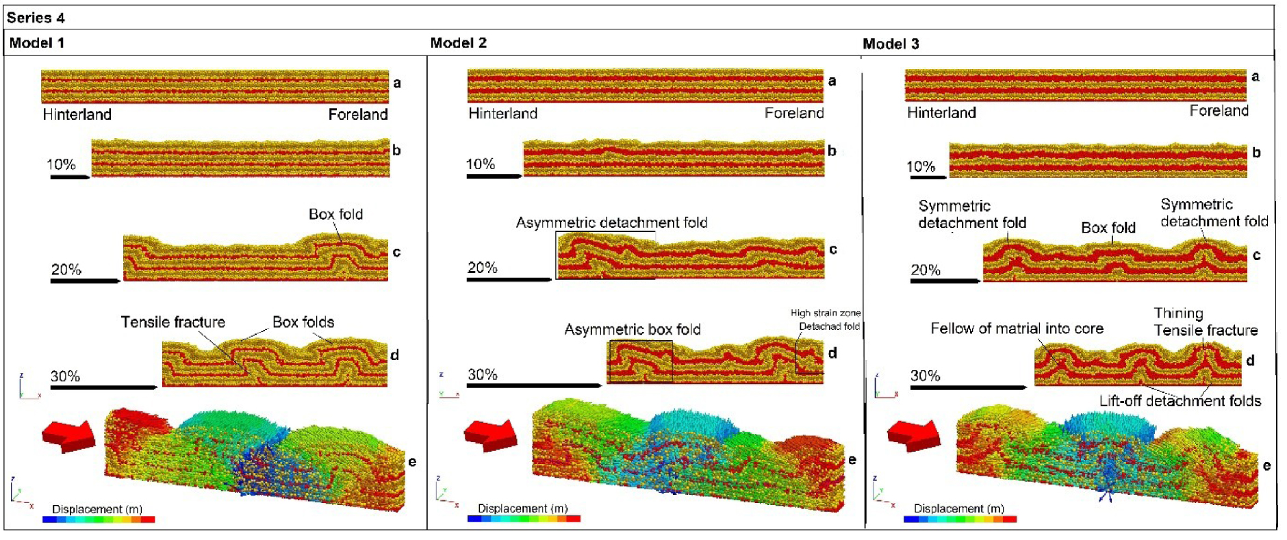
The deformation in the Model 3 of Series 4 experiments started by formation of symmetric décollement fold that developed during shortening by uplift and also extensional fracture/faults in the upper décollement. Martial fellow from décollements into the core of anticline is visible at the 30% of shortening (Model 3d in Figure 5). The type of décollement folds in the final stage is chevron lift-off fold whereby the layers are isoclinally folded in the core of anticline and the ductile materials are flow from the core of the folds. The shortening was accommodated by decoupling, folding and uplift. Total displacement magnitude and direction between the driving hinterland wall and the foreland wall are illustrated and colored for all models (Models 1e, 2e and 3e in Figure 5) as the characteristic of the tectonic shortening accommodated by internal deformation of the model.
3.2.2. Series 5—increasing thickness in the upper décollement
Series 5 (Figure 6) presents to simulate the effects of three décollements on the structural style and evolution of the sedimentary cover sequence consisted of a series of competent bonded layers with the increasing thickness in the upper décollement. Overall, after an initial step of homogeneous shortening, the deformation initiates by flexural slip in the model 1 of series 5 experiments that caused the formation of symmetric box-shaped folds and disharmonic folds in the 20% of shortening (Model 1c in Figure 6) that evolved in the further stages of deformation by uplift and also thickening in the sedimentary layers located in the limbs of folds after 30% of bulk shortening (Model 1d in Figure 6). In model 2 of series 5 of experiments with thicker upper décollement, the deformation initiates by formation of asymmetric folds in 20% of shortening (Model 2c in Figure 6). The folds progressively tighten and developed into lift-off to box fold. This main lift-off fold amplified toward the surface. The formation of forethrust in the core of box fold accrued in 30% of shortening and extensional fracture/faults in the intermediate décollement presents the strain localization (Model 2d in Figure 6). The shortening was accommodated by fold amplification.
The velocity vectors for sedimentary sequence and the evolution of DEM to show the folding in the models 1, 2, and 3 of series 5 for sedimentary sequence with three décollements after 30% (3000 m displacement) orthogonal shortening in three steps of shortening 10%, 20%, and 30%. The models are the same in terms of the thickness of basal and intermediate décollements. The thickness of the upper décollement increases in the study models.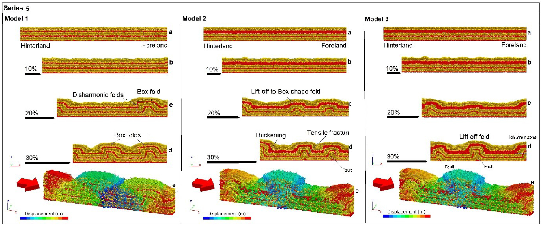
In model 3 of series 5 experiments with thickest upper décollement the deformation started by formation of low amplitude fold and an asymmetric décollement fold without any faults or fractures in 20% of shortening (Model 3d in Figure 6). By increasing the shortening at the further steps in the 30% of shortening, the highly strain fold such as lift-off fold formed that contains the fractures in the core of anticline (Model 3d in Figure 6). These fractures in the layers beneath the upper décollement are the results of contractional environment and fold tightening. There are other disharmonic folds in the layers near the surface that are effective in the topography. Total (relative) displacement magnitude and direction between the driving hinterland wall and the foreland wall are illustrated and colored for all models (Models 1e, 2e and 3e in Figure 6) as the characteristic of the tectonic shortening accommodated by internal deformation of the model.
3.2.3. Series 6—increasing thickness in the intermediate décollement
In model series 6 (Figure 7) that represents the effect of multiple décollements and the variation in thickness of intermediate décollement on the structural style and evolution of the sedimentary cover sequence consisted of a series of competent bonded layers (six competent layers thick) intercalated with less competent bonded layers (three less competent layers thick).
The velocity vectors for sedimentary sequence and the evolution of DEM to show the folding in the models 1, 2, and 3 of series 6 for sedimentary sequence with three décollements after 30% (3000 m displacement) orthogonal shortening in three steps of shortening 10%, 20%, and 30%. The models are the same in terms of the thickness of basal and upper décollements. The thickness of the intermediate décollement increases in the study models.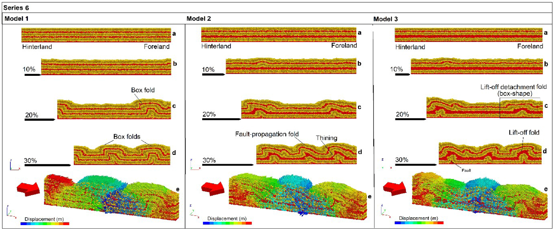
In model 1 of series 6 experiments, deformation initiates by uplift and formation of single symmetric box-shaped décollement folds and also the disharmonic folds in sedimentary layers at the onset of deformation (Model 1c in Figure 7). By increasing shortening, the other box-shaped fold formed after 30% of bulk shortening (Model 1d in Figure 7). In model 2, minor fold structures developed subsequently became a hinterland-verging fault-propagation folds after 20% shortening due to the thickness and rheology of intermediate décollement to accommodate the deformation (Model 2c in Figure 7). After 30% shortening, layers are isoclinally folded in the core of the anticline and the fold developed by uplift and formation of minor folds in the limbs of main folds and structural decoupling and thickening (Model 2d in Figure 7).
In model 3 of series 6 experiments with thickest intermediate décollement the deformation started by formation of rootless minor fold. As deformation continued in the next step of shortening, the low-amplitude lift-off décollement fold with extensional fracture/faults in the core of anticline appeared in the 20% of bulk shortening that evolved by uplift and formation of disharmonic minor folds (Model 3c in Figure 7). This fold is isoclinally folded in the core of the fold that named box lift-off (Model 3c in Figure 7). During progressive deformation, shortening was accommodated by uplift, decoupling, folding with an increase in limb dips at the final stage of the experiment. In this stage all minor and major folds are tightened and the chevron shaped lift-off fold formed (Model 3d in Figure 7). Total displacement magnitude and direction between the driving hinterland wall and the foreland wall are illustrated and colored for all models (Models 1e, 2e and 3e in Figure 7) as the characteristic of the tectonic shortening accommodated by internal deformation.
4. Comparison with a natural example: the Zagros fold-and-thrust belt of Iran
Décollements are necessary to form thin-skinned fold-and-thrust belts and their role has been studied for a long time [e.g., Wilkerson et al. 2007; Lacombe et al. 2016; Humair et al. 2020]. The DE-model results obtained in this study demonstrate that the presence, thickness, mechanical properties, and the number of décollements play key roles in controlling how contractional settings evolve. In this regard, styles of natural fold-and-thrust belts are compared to our modelling results to illustrate the geometry and kinematics of their evolution.
The Zagros orogenic belt, SW Iran, resulted from convergence and shortening between the Arabian plate and the Iranian continental block [Alavi 2004, 2007; Mouthereau et al. 2012]. The Zagros orogenic belt can be divided into several structural zones along strike from the east to the west including the Fars, Izeh, Dezful Embayment, and Lurestan, based on their differences in structural style and tectono-sedimentary [e.g., Alavi 2004, 2007; Mouthereau et al. 2012]. The Zagros fold-and-thrust belt is characterized by a broad symmetric to asymmetric, and gently to isoclinal fold geometries [Sherkati et al. 2005, 2006; Derikvand et al. 2018; Nabavi and Fossen 2021; Shamszadeh et al. 2022b]. The dominant wavelength of such fold structures is 15.8 ± 5.3 km [Mouthereau et al. 2006]. The Zagros fold-and-thrust belt contains several evaporate and/or weak shale layers in the sedimentary sequence which are thick enough to form independent décollements. The nature and influence of the presence of multiple décollements are identified by many researches as an important controlling factor of the structural style in the Zagros belt [e.g., Sherkati et al. 2005, 2006; Sepehr and Cosgrove 2004; Vergés et al. 2011; Farzipour-Saein and Koyi 2014; Ghanadian et al. 2017a, b; Derikvand et al. 2018, 2019; Heydarzadeh et al. 2020, 2021; Koyi and Mansurbeg 2021]. The Dezful Embayment in the Zagros foreland is a classic example of this case, where containing the world’s largest hydrocarbon reserves in a fold belt. In the fold belt, as many as four Jurassic–Cretaceous shale units provide intermediate décollements above the deep Infracambrian Hormoz salt décollement.
Salt/shale-cored décollements folds and some isoclinal lift-off fold geometries are similar to those commonly reported from the other thin-skinned fold-and-thrust belts, however, thrust-related folds and the emplacement of thrust sheets have taken place here due to the presence of multiple décollement horizons [Pla et al. 2019]. Evaporite-cored anticlinal structures formed as décollement folds during tectonic shortening and the ductile flow of evaporite in the anticline core are resulting in an evaporite thickening. Subsequently, deformation is localized in the evaporite-cored anticlinal structure, which are structurally accommodated by fore-thrusts and back-thrusts generating fault-propagation folds and pop-up structures. Fishtail structures, which are a type of triangle zones in thrust systems, are also one of the other common structures in contractional deformation zones with multiple décollements. In this area, short wavelength anticlines in the Oligo-Miocene Asmari Formation are interpreted to be detached in the Pabdeh and Gurpi or in the Kazhdumi formations [Sherkati et al. 2005; Derikvand et al. 2018, 2019; Heydarzadeh et al. 2021; Shamszadeh et al. 2022b]. Above these shale décollements, the Miocene Gachsaran Formation provides a shallow salt décollement 1 to 2 km thick in the Dezful Embayment [Sherkati et al. 2006; Ghanadian et al. 2017a, b; Derikvand et al. 2018, 2019]. Structural coupling across this shallow décollement is high, so that anticlines above the décollement tend to overlie anticlines below the décollement. In contrast, where structural coupling is low, folds form disharmonic geometries above and below the Gachsaran décollement, and create exploration challenges in the Asmari Limestone reservoir.
Furthermore, the Gachsaran evaporates may migrate from anticlines to adjacent synclines in the Lurestan structural zone, in which thrusts affecting the overlying sequences and develop significant disharmonic fold geometries. Such disharmonic fold geometries in the overlying Asmari Formation occurs where the thickness of the interposed incompetent units exceeds a critical thickness that leaves the Asmari limestone outside of the contact strain zone of the Bangestan limestones buckles. Disharmonic fold geometries, however, vanishes toward the southwest, where the Asmari limestone and the top of the Late Cretaceous Bangestan limestones are roughly concordant, implying a change in the décollement properties. Sedimentary package of the Oligocene–Miocene Shahbazan–Asmari unit and the Bangestan Group was folded harmonically and display short-wavelength in geometry [Casciello et al. 2009; Vergés et al. 2011; Farzipour-Saein 2017]. Disharmonic décollement folds can be seen in DE-models of series 4 and also DE-models 2 and 3 of series 6 experiments in the present study that are buckle folds on different wavelength. Disharmonic fold geometries across décollements may produce sharp transition of geometric characteristics due to the interlayering of competent and incompetent beds. In addition, it should be noted that several parallel or concentric folding structures have been developed in Zagros fold-and-thrust belt. Such parallel folds exhibit broad anticlines and narrow synclines in the upper units and vice versa in the intermediate and upper décollements, that is particularly comparable with DE-models of series 4 experiments in the present study (i.e. Model 3c and 3d in Figure 5). Furthermore, the lithostratigraphic units between two major décollements in the Zeloi anticline (Dezful Embayment, SW Iran) display different fold geometries (Figure 8) [Derikvand et al. 2019], which is comparable with the model 3 of series 6 that has thicker intermediate décollement compared to the other two models. Overall, models with thick décollements show a further developed deformation and more complex fold and fault structures, partically in the overlying strata, at the final stage of shortening (i.e. 30%) compared to models with thin décollements (like the model 2 of series 6).
Structural cross-section on the southern part of the Izeh zone and the northern part of the Dezful Embayment. The Hormoz series and the Garau to Dashtak formations controlled the geometry of folds as the major décollement horizons [Derikvand et al. 2018].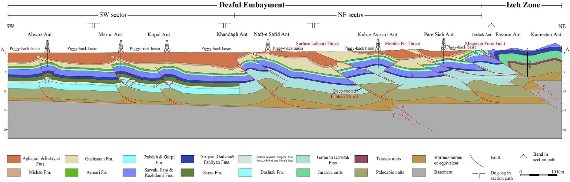
5. Comparison to previous modelling studies
Critical tapered-wedge theory has been successfully applied to the study of the deformation mechanism and kinematic evolution of fold-and-thrust belts and accretionary prisms in contractional settings [e.g., Davis et al. 1983; Dahlen 1984, 2003; Buiter 2012]. The theory indicates that the critically tapered wedge, as a stable geometry, slides along the basal décollement without internal deformation and is dependent on the basal friction coefficient and the internal strength of the material. According to the modelling results, when the wedges are in subcritical or supercritical states, the ramp–flat structure and vertical uplift in the hinterland increases the slope angle to approach the critical angle. Furthermore, hinterland-verging fault-propagation folds, as a backthrust, were developed in DE-models when the wedge at the front of the deformation belt is in a subcritical state, backthrusting along the intermediate and/or upper décollement steepens the wedge so as to approach the critical angle.
Many thin-skinned fold-and-thrust belts are formed above multiple décollements producing different structural styles with complicated fold and fault geometries. So that, fold geometry in fold-and-thrust belts is an important issue for hydrocarbon exploration [Nabavi and Fossen 2021]. In thin-skinned fold-and-thrust belts, décollements are frequent, and their impact has long been explored by means of various techniques [Davis and Engelder 1985; Homza and Wallace 1995; Konstantinovskaya and Malavieille 2011; Gu et al. 2021]. In this regard, the structural evolution of thin-skinned fold-and-thrust belts has been investigated in several analogue and numerical models. Overall, there is a general agreement between our numerical modelling results with scaled analogue and numerical models that simulating the evolution of multiple décollement thin-skinned fold-and-thrust belts.
Ghanadian et al. [2017b] (Figure 9) have documented how an additional intermediate décollement and its thickness variations promotes folding and thrusting of the heterogeneous sedimentary sequence in the Dezful Embayment, as well as the role of strain rate. We numerically obtained a similar evolution with two décollements that the upper décollement surrounded by competent layers (i.e. series 1 experiments in this study) and three décollements in which the intermediate décollement thickness varies (i.e. series 6 experiments in this study) (Figure 7). Farzipour-Saein [2017] and Farzipour-Saein and Koyi [2014] also investigated the structural effects of basal and intermediate décollements in the Lurestan, Fars and Izeh structural zones using a series of scaled sand-box analogue models. Their results and our numerical models with two weak décollements are comparable.
(a) Model 4 from the study conducted Ghanadian et al. [2017a, b] is compared to our modelling outcome (b) and (c). that are series 1 model 3d and series 6 model 2d from our numerical investigation respectively.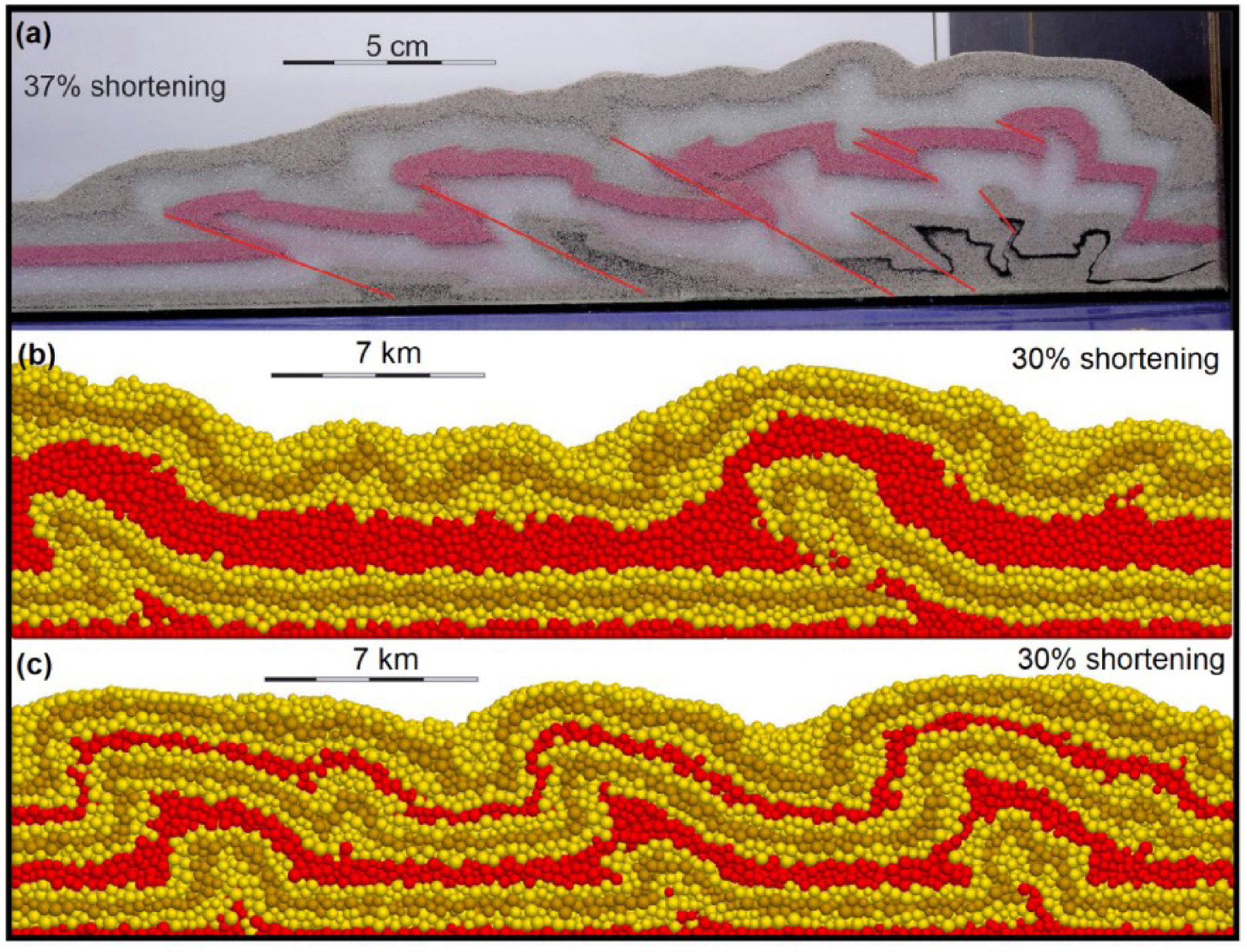
Furthermore, the analogue modelling results by Pla et al. [2019] demonstrate that as the viscosity of the décollement increases, the deformation propagates more slowly from hinterland to the foreland part of the fold-and-thrust belt, and the underlying thrust stack becomes broader and lower and has a gentler thrust taper angle. The rheology of the décollement defines the distribution and geometry of the sedimentary cover detached on it that in turn influence the structural style and development of fold and thrust structures.
Moreover, Cui et al. [2020] investigated the role of a strong basal décollement and a weak upper décollement with different strengths by a series of analogue models to simulate the structural style and deformation patterns of the Longmen Shan fold-and-thrust belt, eastern margin of the Tibetan Plateau. Their modelling results show that models with no upper décollement and/or with a strong frictional upper décollement deform in the in-sequence forward-breaking style. However, models with a strong basal décollement and weak upper décollement deform in the out-of-sequence style. Hence, the spatial relation of a strong basal and weak upper décollements may be one of the important factors producing the structural style.
Furthermore, there are several numerical models that have been applied to explain the tectonic evolution of thin-skinned fold-and-thrust belts. Morgan [2015] and Hughes [2020] highlighted the essential role of cohesive strength and residual strength of the basal décollement in the nucleation of discrete faults, the specific styles of structures that develop in fold-and-thrust belts using a series of 2D discrete element models. Also, Meng and Hodgetts [2019a, b] used 2D discrete element method to simulate thin-skinned tectonic deformation in stratigraphic sequences with two décollements, to yield new insights into the combined control of rock competence, depth and thickness of the upper décollement on structural styles and decoupling characteristics. In this regard, rock rheology and décollement layer thickness can greatly influence thin-skinned tectonics in systems with multiple décollements, and determine the degree of structural decoupling. Their DE-modelling results indicate models with a lower cohesion and a thinner décollement resulted in more distributed strain and a larger number of folds, whilst models with a higher cohesion and a thicker décollement led to localized shear zones in fewer folds. In addition, surface uplift and fold amplitude are mainly positively affected by the décollement thickness, so that, the greater the surface uplift and fold amplitude are developed in models with the thicker décollement [Meng and Hodgetts 2019a, b] (such as Figure 10). We numerically obtained comparable results and similar evolution in model series 1 to 3 of the present study with basal and upper décollements within the cover sequence, which are structurally comparable with DE-models by Meng and Hodgetts [2019a, b]. Modelling results of the present study indicate that competent layers are characterized by localized strain zones as fault-bend, fault-propagation folds and pop-up structures with tensile fractures developed in fold hinges. Moreover, thicker intermediate and upper décollements can provide the higher the degree of decoupling, sufficient mobile materials to fill fold cores and development of disharmonic folds.
DE-modelling results of model 5 in series 2 with a thin upper décollement; and model 14 in series 6 with a thick upper décollement [after Meng and Hodgetts 2019b].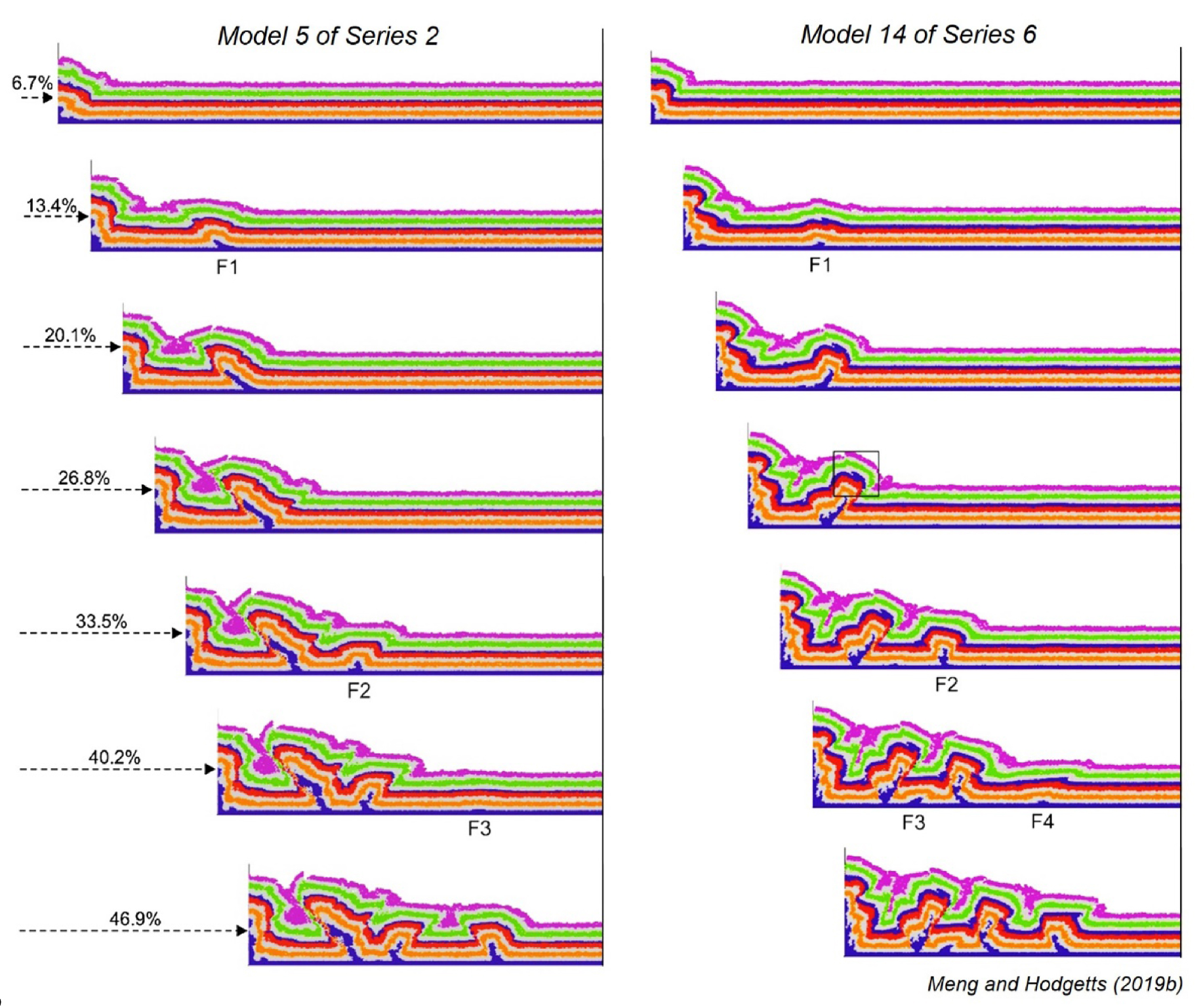
6. Conclusions
Thin-skinned fold–thrust belts commonly contain multiple décollements that exhibit first-order control on their evolution and structural styles. Décollements cause the fold style and fold–fault interactions to become more complex, as well as structures formed under the influence of décollements are the locations where hydrocarbons can be found. Another known factor is the importance of mechanical property contrast between layers based on strength differences. As a result, numerical modelling is used as one of the methods available to better investigate the effect of the above variables. Therefore, in this paper, we focused on the role of a few core factors to study of the structural evolution of thin-skinned fold-and-thrust belts. We have used the discrete element method (DEM) to carry out a series of numerical models to analyze the differences in the structural evolution and style of thin-skinned fold-and-thrust belts causing from the thickness of décollements, the number of décollements, the rheological contrast. Finally, we tried to compare the resulting models to structures and kinematic features of natural structures, however we do not claim that these models exactly reflect natural structures.
As a result of horizontal shortening, a variety of fold styles, such as décollement, fold-bend and fold-propagation folds were generated by varying décollement thickness and cover rock cohesiveness. Thicker décollements can develop greater surface uplifts and provide sufficient materials to fill fold cores and development of disharmonic and larger folds in geometry. The presence of a thick intermediate décollement facilitated decoupling on cover rock, forming a significant contrast in the deformation pattern between the underlying and overlying layers. The modelling result suggests that the presence of décollements and their number and mechanical properties are considered to be a key parameter in the evolution, structural style, deformation pattern and strain partitioning of thin-skinned fold-and-thrust belts. The modelling results are compatible with the Zagros fold-and-thrust belt, SW Iran, especially the Dezful Embayment zone, as well as previous analogue and numerical models, regarding the structural styles, indicating that the combination of increasing thickness in intermediate and upper décollements and a less-competent cover rock could preferentially produce a range of fold styles including sinusoidal, box, fault-propagation and fault-bend folds. This study demonstrates a strong influence of décollement thickness and rock mechanical properties on the structural styles of fold-and-thrust belts.
Conflicts of interest
Authors have no conflict of interest to declare.
Author contributions
NE: Project administration, Field work, Conceptualization, Methodology, Software, Formal analysis, Validation, Investigation, Visualization, Resources, Data Curation, Writing—original draft, review and editing. SAA: Supervision, Investigation, Resources, Data Curation. STN: Conceptualization, Conceptualization, Investigation, Visualization, Resources, Data Curation, Writing—review and editing. MRG: Resources, Writing—review and editing.
Acknowledgements
The first author greatly thanks Professor Martin Schöpfer (University of Wien, Austria) for the excellent guidelines and feedback on an early version of modelling procedures.