

Version française abrégée
1 Introduction
Un des objectifs du puits AG10 est de comprendre l'impact des structures tectoniques sur les écoulements dans les carbonates compacts [8]. Ce puits, foré verticalement, recoupe la faille d'Aigion (Fig. 1) à 761 mbbop (mètres sous l'outil de prévention des éruptions, localisé à 4,2 m au-dessus du niveau de la mer). La faille d'Aigion est une faille normale récente [6], d'orientation N90–100, liée à l'ouverture actuelle du rift de Corinthe [1,6,9]. Il a été carotté entre 710 et 791 mbbop et Schlumberger a acquis des logs UBI (Ultrasonic Borehole Imager) et FMI (Formation Micro Imager) entre 710 et 1003 mbbop. Dans cette section, le puits traverse principalement des carbonates turbiditiques profonds (voir, dans ce numéro, [11] pour une présentation détaillée du contexte géologique). Le présent article synthétise les observations macroscopiques réalisées sur les carottes et les images de puits. Elles sont utilisées pour décrire les microstructures reliées à la faille d'Aigion et leur relation avec les écoulements au voisinage du puits.

AG10 location map. The main normal fault zones come from [7].
Localisation du puits AG10. Les failles normales principales sont tirées de [7].
2 Interprétation structurale
Les données FMI et UBI ont été chargées, traitées et interprétées dans le logiciel GEOFRAME™. Les photos de carottes ont été comparées avec les logs d'imagerie, pour faciliter l'interprétation et orienter les carottes.
En moyenne, la stratification est pentée vers l'est, en accord avec l'orientation générale des structures helléniques. Dans la partie haute du puits, un changement brutal de cette orientation (NW–SE à nord–sud) (Fig. 2(a), (b)) a lieu en traversant une faille à 774 mbbop. Cette faille est un objet majeur, car elle est observée sur les VSP et a induit des pertes de boue durant le forage.
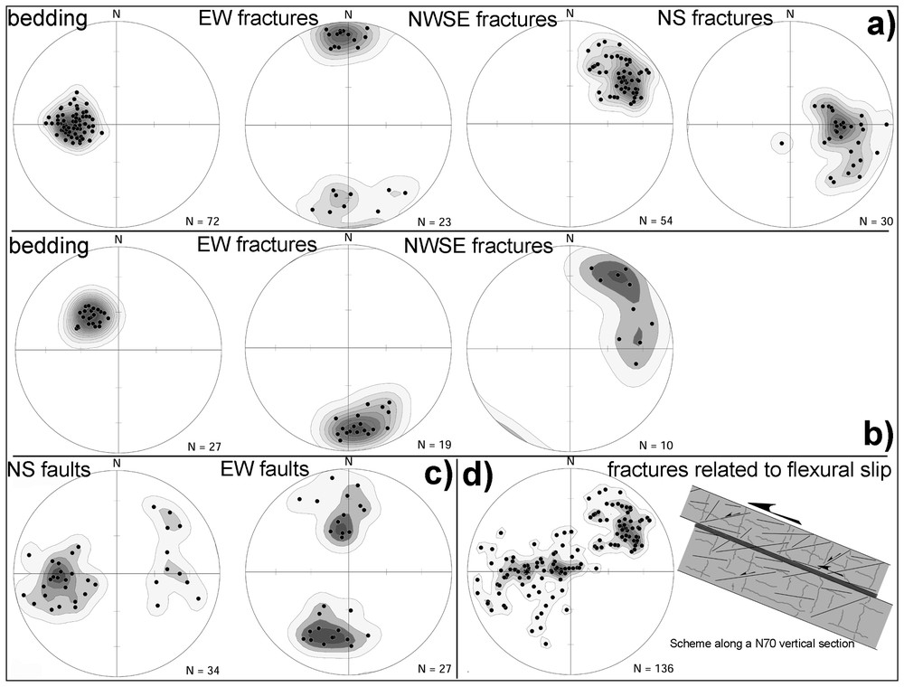
Equal area, lower hemisphere projection of the poles to planes interpreted on borehole images. Density contours are obtained by a Gaussian weighting function, whose size is chosen so that the expected count (E) is equal to the data standard deviation (S). The lower contour corresponds to a count equal to E. The spacing of the contours is . (a) Poles above 744 mbbop. (b) Poles between 744 mbbop and the Aigion Fault. In (a) and (b), the NW–SE planes correspond to stylolites more or less reopened during extension. (c) Poles to faults. (d) Fractures subparallel to bedding and tectonic stylolites (from (a)). The scheme suggests the following scenario: compaction, then compression creating first tectonic stylolites and second folds, inducing flexural slip (grey lines correspond to tectonic and stratiform stylolites and thin black lines to fractures).
Projection conservant les aires des pôles de plans interprétés sur l'imagerie de puits. Les contours de densité sont obtenus par une fonction de pondération gaussienne, dont la taille est choisie de manière à ce que l'espérance (E) du comptage soit égale à l'écart type des données (S). Le premier contour correspond à une densité de E. L'espacement des contours est . (a) Pôles au-dessus de 744 mbbop. (b) Pôles entre 744 mbbop et la faille d'Aigion. En (a) et (b), la famille NW–SE correspond à des stylolites plus ou moins réouverts par l'extension. (c) Pôles des failles. (d) Fractures subparallèles à la stratification et stylolites (voir (a)). Le schéma suggère l'évolution suivante : compaction, puis compression, créant d'abord des stylolites tectoniques et puis des plis induisant du flexural slip (les traits gris représentent les stylolites tectoniques et stratiformes et les fines lignes noires des fractures).
La faille d'Aigion est la structure principale observée dans le puits AG10 (Fig. 4). Son intersection avec le puits et sa trace en surface démontrent que son pendage vers le nord est compris entre 55° et 60°. Le cœur de la faille est composé d'argiles cisaillées provenant principalement de radiolarites. Une zone de 12 m d'épaisseur de calcaires très bréchifiés constitue la zone endommagée. La pression solution entre les éléments fracturés de la brèche est un mécanisme de déformation fréquemment observé. Dans le mur de la faille, l'épaisseur de cette zone (9 m) est identique à celle observée à l'affleurement pour la faille d'Helike [6]. Ces failles ayant des rejets très différents (respectivement voisins de 170 et 500 m), il n'est pas possible de définir une relation entre eux et l'épaisseur de la zone endommagée.
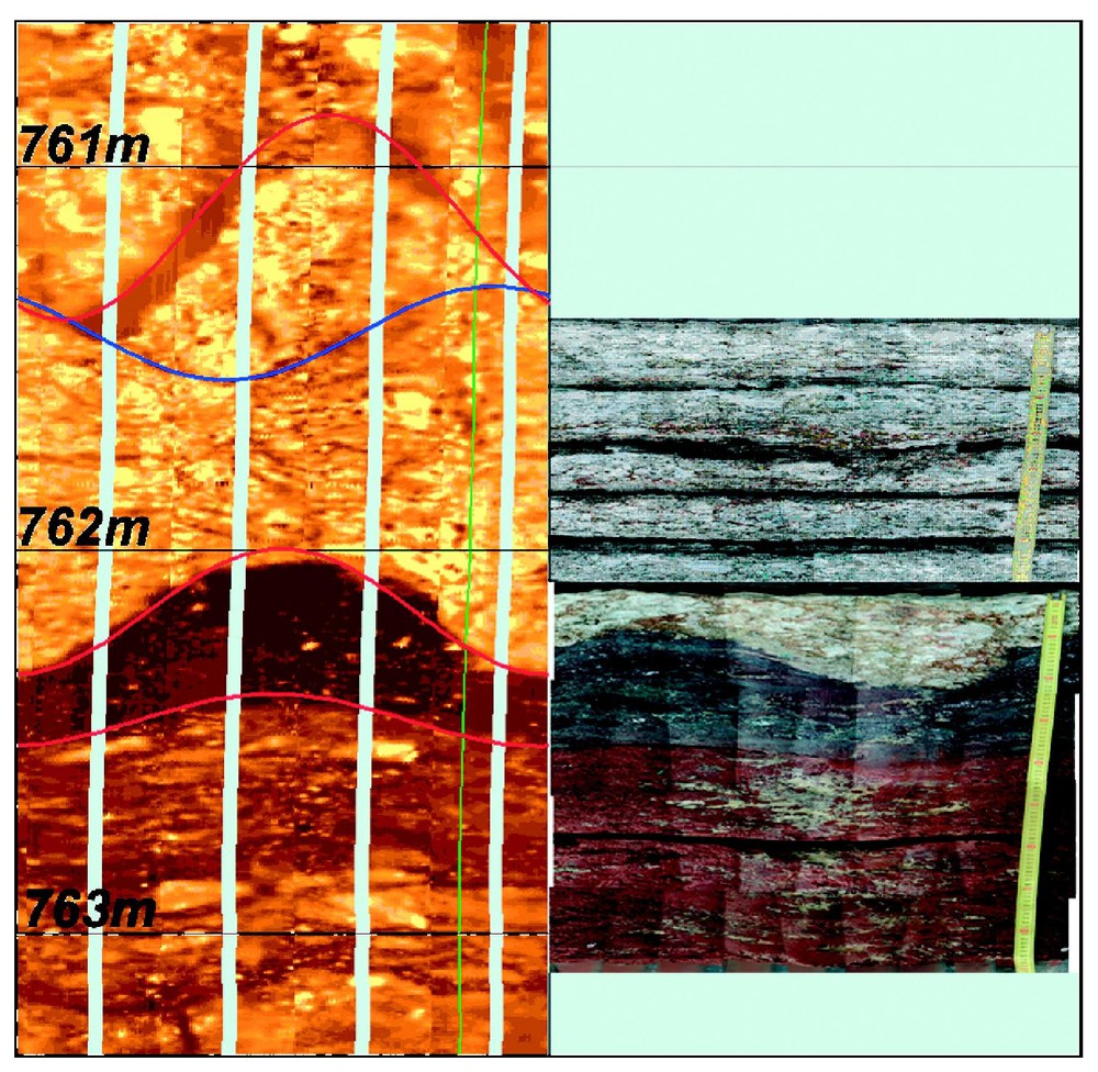
Aigion Fault, FMI (left) and core surface pictures. Depths are measured in meters bellow BOP. The horizontal axis corresponds to the borehole circumference (∼50 cm). Going from left to right corresponds to a northeast–southwest–north path. Red sinusoids correspond to faults, blue ones to open fractures. Below the fault plane, in the fault core, the dark and red layers are clays derived from clays and radiolarites sheared along the fault plane.
Faille d'Aigion, FMI (gauche) et déroulé de carotte. Les profondeurs sont mesurées en mètres à partir du BOP. L'axe horizontal correspond à la circonférence du puits (∼50 cm). Aller de la gauche vers la droite correspond à un chemin nord-est–sud-ouest–nord. Les sinusoı̈des rouges correspondent à des failles, les bleues à des fractures ouvertes. Sous la faille, dans le cœur de la faille, les niveaux noirs et rouges sont des argiles provenant d'argiles et de radiolarites cisaillées le long du plan de faille.
Trois familles de fractures sont observées dans le puits (Fig. 2(a), (b)). Une famille est–ouest correspond à des fractures largement ouvertes, partiellement remplies de calcite (Fig. 5). Elles sont postérieures à la rotation du pendage de la stratification observée à 744 mbbop. Cette famille est clairement liée à l'extension récente. Les densités de fractures mesurées à partir des données de puits n'augmentent pas quand on s'approche de la faille. Une famille NW–SE correspond à des stylolites tectoniques plus ou moins réouverts, fournissant une direction NNE–SSW correspondant à la compression hellénique. Les données étudiées jusqu'ici ne permettent pas de proposer une origine tectonique argumentée pour une famille nord–sud (voir suite). Finalement, deux familles de failles peuvent être décrites (Fig. 2(c)). L'une correspond à des failles parallèles à la faille d'Aigion, l'autre à des failles nord–sud. Là encore, l'origine des failles nord–sud reste à définir.
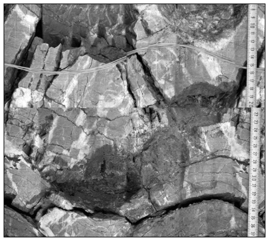
East–west open fractures perpendicular to bedding (Box 31, core 12-6, 746 mbbop).
Fractures ouvertes est–ouest perpendiculaires à la stratification (boı̂te 31, carotte 12-6, 746 mbbop).
On notera que nombre de structures ne sont pas dues à l'extension récente. En plus des stylolites tectoniques déjà mentionnés, des cisaillements parallèles à la stratification affectent les calcaires de manière très pénétrative (Fig. 2(d)). Les critères cinématiques qui leur sont associés montrent qu'ils correspondent à du glissement banc sur banc pendant les épisodes compressifs. De plus, en dehors de la zone très endommagée associée à la faille d'Aigion, le puits recoupe de nombreux niveaux de brèches subhorizontaux (Fig. 6). Ces niveaux sont généralement constitués de protobrèches, confinées entre des limites de bancs. Ils sont très faiblement cimentés et largement oxydés. Les quelques critères cinématiques qu'ils contiennent indiquent un cisaillement vers l'est, parallèle à la stratification. Cette cinématique est incompatible avec le glissement bancs sur bancs lié à la compression à vergence ouest. En revanche, ils pourraient correspondre à une phase d'extension Miocène [5] ou à une extension parallèle à la faille d'Aigion accommodant la flexuration du toit de cette faille [12]. L'analyse comparée des ciments des différentes familles de fractures et des études de terrains devraient permettre de pouvoir de choisir l'une de ces deux hypothèses ou d'en proposer d'autres. Quoi qu'il en soit, la déformation associée à ces niveaux subhorizontaux de protobrèches est compatible avec l'apparition des failles et des fractures nord–sud.
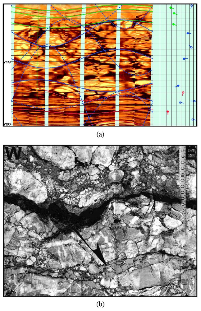
Brecciated layers parallel to bed boundaries. (a) FMI (left) over a 2 m interval at 719 mbbop; horizontal axis, see Fig. 4 comments. On the tadpole display: blue=fractures, red=fault, green=bed boundary. Note that the fractures inside the brecciated layer dip in the same direction as the bed boundary, 30° steeper. (b) Core 1–3 Box 3: north–south normal fault confined in a brecciated layer parallel to the bedding. These geometries are compatible with a top-to-the-east sense of shear parallel to stratification.
Niveaux bréchifiés parallèles à la stratification. (a) FMI (gauche) sur un intervalle de 2 m à 719 mbbop, pour l'échelle horizontale : voir Fig. 4. Sur le diagramme à clous : bleu=fractures, rouge=faille, vert=limite de bancs. Remarquez que la direction de pendage des fractures dans le niveau bréchifié est la même que celle des bancs, 30° plus raide. (b) Carotte 1–3, boı̂te 3. Faille normale nord–sud confinée dans un niveau de brèche parallèle à la stratification. Ces géométries sont compatibles avec un cisaillement vers l'est parallèle à la stratification.
3 Discussion et conclusion
Les structures liées à la compression sont, soit des stylolites, soit des fractures très cimentées. Elles induisent une diminution de la perméabilité, comme l'argile cisaillée le long du plan de la faille d'Aigion. À l'opposé, les fractures associées à la faille d'Aigion ne sont que très partiellement cimentées et elles doivent augmenter sensiblement la perméabilité. Les brèches associées à la faille sont riches en argile et très oxydées dans le toit, alors qu'elles sont vacuolaires et recouvertes par un film de calcite très fin dans le mur. Ces observations expliquent bien le comportement hydraulique du puits pendant le forage quand il a traversé la faille : un excès de pression a été observé et il est devenu éruptif avec un déclin négligeable de sa productivité dans les jours qui ont suivi. À partir de ces observations, les écoulements apparaissent principalement contrôlés par les failles majeures.
Ce travail a démontré également que les carottes et l'imagerie de puits sont bien complémentaires pour mener de manière satisfaisante l'analyse structurale d'un puits. Les logs fournissent une description continue du puits, que les carottes permettent de calibrer. En particulier, sans les carottes, il aurait été très difficile de distinguer les stylolites tectoniques réouverts des fractures ouvertes. Les carottes permettent, par ailleurs, de réaliser l'échantillonnage nécessaire à une analyse microstructurale couplée à l'étude de la diagenèse. Ce type d'analyse est indispensable pour préciser le calendrier tectonique et l'impact des microstructures sur les écoulements. Dans le cas de la faille d'Aigion, cela permettra de répondre aux questions suivantes : y a-t-il de la pression solution associée à la phase extensive récente en dehors des zones de brèches ? Quelle est l'origine des failles et des fractures nord–sud ? Comment expliquer la distribution de l'oxydation et de la calcite limpide de part et d'autre de la faille ?
1 Introduction
In compact carbonates, fault and fractures provide the main conduits for fluids. Understanding how they control fluid flow is a major issue for water resources and hydrocarbon production. This was one of the main objectives of AG10 well drilled through the Aigion normal fault [8] (Fig. 1). This active fault is located on the southern coast of the Gulf of Corinth, one of the graben cuttings through the Hellenides [2,3,13]. In this area, the Hellenides are mainly west verging along north–south to NW–SE thrusts and they are affected by Miocene and Pliocene extension [1,4,5,9].
AG10, drilled vertically, intersects the Aigion Fault at 761 m below blow out preventer (mbbop), located 2.2 m above ground level. It was cored between 710 and 791 mbbop and Schlumberger acquired UBI and FMI from 710 down to 1003 mbbop. Turbiditic deep marine carbonates are found in this section [11]: mudstone to grainstone limestones intercalated with marls and thin shaly layers. AG10 therefore provides a useful database to study the structural impact of a normal fault on limestone tectonic fabric and its influence on fluid flow. We present here macroscopic observations of cores and image logs. They are used to describe the microstructures related to the Aigion Fault and to earlier deformation events and their relationship with fluid flow.
2 Data
UBI provides acoustic images of the borehole with 100% coverage. FMI corresponds to high-resolution resistivity measurements covering only 80% of the borehole circumference. However, as it detects resistivity contrast it is able to differentiate between open and cemented fractures. In the following, conductive stands for electrically conductive with respect to the surroundings. Due to its better resolution, the FMI was chosen as the reference for interpretation. UBI and FMI have been loaded, processed and interpreted in GEOFRAME™. In addition, core surface photos were compared to the image logs to facilitate interpretation and to orient the cores.
3 Structural interpretation
3.1 Rationale used for interpretation
Interpretation began by core analysis. This a priori knowledge and the comparison between logs and core photos provided an efficient guide to interpretation.
On image logs, two types of geological features are easily differentiated: bed boundary and fractures. Bed boundaries correspond to continuous and regular conductive sinusoids imaged on the complete borehole circumference. Their dip rarely exceeds 45°. Fractures correspond to sinusoids with changing width. They frequently stop at bed boundaries and their dip is highly variable. From core description, the carbonates appear heavily fractured with many infracentimetric fractures. Our interpretation only includes the fractures defined by an unambiguous sinusoid meaning that only fractures with length greater than 10 cm were considered.
Some of the fractures are faults. The criteria we used to identify faults on images are: facies changes across fractures, bed boundary deformation at fractures, and observation of slickensides on cores. Due to the image resolution, some of the planes labelled as fractures might be faults. On the contrary, the criteria used for fault labelling ensure a reliable assignment.
3.2 Bedding dip and faulting
Above the Aigion Fault, bedding is organised in two sections (Figs. 2(a), (b) and 3). Above 744 mbbop, dips are plunging at 45° toward the east; below 744 mbbop, dips are plunging at 45° to the southeast. The average east-dipping attitude is coherent with the ante-rift structure being controlled by westward thrusting. At 744 mbbop, in accordance with the sharp change in bedding dips, a fault is observed on cores. Its dip cannot be defined because of core damage and of the poor image quality at the fault plane. The fault is also marked on VSP [10] and has an impact on fluid flow (mud losses during drilling). It is therefore one of the major intersected structures. The Aigion Fault corresponds to a large change in bed attitude (Fig. 3) appearing as the main structural feature intersected by AG10. The section located below the 744 mbbop fault and above the Aigion Fault appears as rotated block.

Bedding strike measured along AG10 well.
Orientation des plans de stratification le long du puits AG10.
3.3 The Aigion Fault zone
At 761 mbbop, the Aigion Fault is the major structural feature intersected by AG10 (Fig. 4). A dip of 60° toward the north can be computed linking the depth of intersection to the fault surface trace. It compares well with the 55° dip measured on imagery log and is confirmed by the VSP [10].
From core observation, the fault core is a 1 m-thick band made of sheared clay derived from radiolarites. Above and below, brecciated limestones constitute the heavily damaged zone. On the FMI images (Fig. 4), the breccias are identified by the spotty character of the images, the complete loss of stratification and conductive fractures. Inside these breccias, indentation of fractured elements is frequent and accommodated by pressure solution. The thickness of this zone is 3 m above the fault and 9 m below. The thickness measured in the footwall is in agreement with the one measured for the Helike fault affecting similar lithologies at its intersection with the Selinous River (Fig. 1) [7]. As the estimated throw for the Helike fault at this location (500 m in [6]) is three times larger than the Aigion Fault one near AG10 (150 to 200 m from geological and VSP data [10]), the width of the brecciated zone appears poorly correlated with the throw.
3.4 Fractures and small faults
Because of the high core recovery above the Aigion Fault plane, we focus in this paper on the hangingwall description. Three main fracture sets are observed: east–west, NW–SE and north–south (Fig. 2(a), (b)).
The east–west set can be related to the Aigion Fault for the following reasons: (i) on cores, east–west fractures open and partially filled with calcite (Fig. 5); (ii) they postdate the rotation of the bedding related to the 744 mbbop fault because their strike remains constantly parallel to Aigion Fault as bedding is rotated. The number of fractures observed per metre is only slightly higher below than above 744 mbbop (1 and 0.7 fracture per metre, respectively). It is therefore very difficult to define the size of the damage zone related to the Aigion Fault. The NW–SE set is well developed above the 744 mbbop fault. It corresponds to stylolites related to layer parallel shortening. Even if some of these stylolites were opened by later tension, most of the NW–SE fractures are completely sealed by calcite and we do not expect that they contribute much to the fracture permeability of the pre-rift carbonates. This set is best expressed above 744 mbbop, because the mudstones in which stylolites are best developed are mainly observed above this depth. Below 744 mbbop, facies include more marly limestones and packstones that inhibit the development of stylolites. The last set trends north–south. More data are required to propose a reliable origin for this set (see below and Section 3.6). The study of the cements sealing these fractures and its comparison with others should provide the missing information.
Finally, two fault sets are observed (Fig. 2(c)). The first one corresponds to normal faults parallel to the Aigion Fault. They occurred all along the well, not clustered near the Aigion Fault. The second set has a north–south average strike. With respect to the bedding, it is made of normal fault dipping at high angle and low angle faults with ambiguous kinematics. Their striations mostly trend east–west and these north–south faults can correspond either to the east–west compressive phase (Section 3.5, shear along stratification) or to east–west extension (Section 3.6) or both.
3.5 Structures related to the Hellenides compression
Aside from the east–west fractures, a large part of the microstructures seen along AG10 borehole can be related to tectonic phases predating the Pliocene to present-day extension. Only one third of the macroscopic fractures can be reliably related to the recent extension. This ratio is strongly reduced if structures created by bed parallel slip, stylolites and microfractures seen on cores, are considered.
First, tectonic stylolites are well developed in mudstones. They strike between NW–SE and NNW–SSE (Fig. 2(a)), indicating a N50–N90 compression (assuming that stylolitic picks are perpendicular to stylolitic planes) in agreement with the trend of the thrusts. In addition, numerous evidences of shear along bedding planes are unambiguously related to flexural slip related to compression. These evidences include:
- (i) striation focussing along a N50–N90 direction with top to the west sense of shear (i.e., updip);
- (ii) fractures weakly oblique to bedding (Fig. 2(d)) and related to bed parallel shear by core observation.
3.6 Bed parallel brecciation
A frequent deformation mechanism observed in AG10 is cataclasis. Apart from the Aigion Fault damage zone, numerous bed-parallel brecciated layers are observed (Fig. 6). As those related to the Aigion Fault, these breccias are affected by pressure solution at the contact point between their fractured elements. However, they have distinct characters.
- (i) They are confined between bed boundaries.
- (ii) They show a weak calcite cementation.
- (iii) They are largely oxidised; and
- (iv) Generally correspond to protobreccias (sedimentological structures are partly preserved).
- (i) small normal faults found inside these layers generally root inside bed interfaces and are ENE verging (Fig. 6(b));
- (ii) fractures affecting them make a 30° angle with respect to bedding and look like Riedel shear planes.
These observations suggest that the kinematics of these brecciated layers correspond to normal movements along the bedding planes. This kinematics is not compatible with the top the western sense of shear related to flexural slip (see Section 3.5). They could correspond to the Miocene extension phase [5] or to accommodation of a fault parallel extension, as suggested in [12], as an alternative to regional permutation of principal stresses during the recent extension phase. The microstructural analysis of the core samples and further outcrop surveys are required to confirm one hypothesis or the other. Note that this tectonic event can be also responsible for the development of north–south fracture and fault sets.
4 Discussion and conclusion
4.1 Tectonic fabric in AG10
Observations made on AG10 cores and image logs demonstrate that most of the rock fabrics are inherited from tectonic phases predating the recent extension affecting the Gulf of Corinth:
- (i) pressure solution features mostly correspond to compaction (stratiform stylolites) and to the Hellenides compression phase striking ENE–SSW;
- (ii) a lot a ‘ductile fabrics’ and fractures (bed parallel fractures) are related to flexural slip associated to the Hellenides.
Tectonic structures undoubtedly associated to the Aigion Fault consist in:
- (i) clay shearing along the fault plane;
- (ii) intense brecciation in a 12 m-thick band parallel to the fault plane; and
- (iii) open to partly cemented fractures striking parallel to the fault plane.
The second main tectonic feature is the fault observed at 744 mbbop. This fault is an important structure at the scale of the well, because it induces a clockwise rotation of the bedding of 45° about a vertical axis. Several observations suggest that it corresponds to a structure predating the recent extension:
- (i) this feature appears as a low dipping structure on core;
- (ii) fractures related to the Aigion Fault strike in the same direction on both sides of this fault;
- (iii) as the striation corresponding to flexural slip that stay focused to the WSW (i.e., above the fault plane they strike parallel to the dip of the bedding, below they are oblique to it);
- (iv) the density of bed-parallel fractures increases in the vicinity of this fault.
These observations support the fact that the Aigion Fault affects a heavily pre-structured rock mass. The relative scarcity of microstructures related to Pliocene recent extension can be related to this characteristic: reactivation of pre-existing structures could be easier than the creation of new ones. To discuss this point in more detail, an improved description of the deformation due to reactivation during extension is still to be performed on AG10 data. This is a major issue for the microstructural analysis of the thin sections collected in AG10, for further outcrop description in this area and for the geomechanical simulation of the Gulf of Corinth fault system.
4.2 Tectonic and fluid flow
As the tectonic structures related to compression either correspond to pressure solution features or old fractures that are generally cemented by calcite, these structures must induce a permeability reduction, as clay shearing along the Aigion Fault plane. At the opposite, fractures related to the Aigion Fault correspond to permeability enhancement, because they are widely open and their cementation is partial. The role of the fault-related breccias is more complex, because their characteristics depend on their position relative to the fault. Above, the breccias are rich in clay, heavily oxidised and strongly indented by pressure solution. This must induce permeability reduction. Below, the clay content is almost null, the carbonates becomes vuggy, with only a thin film of clear calcite deposits. A permeability enhancement is expected. These observations are perfectly in line with the hydraulic behaviour of the well: pressure excess was encountered when crossing the fault and the well became artesian, with a very slow decrease of productivity through time. These phenomena can be easily explained by hydrodynamic characteristics of a heavily fractured, poorly cemented footwall, sealed by the sheared clay core and the upper-cemented clay rich breccias. From these data, fluid flow seems to be mainly controlled by the main faults and the associated structural features. Interestingly, the pressure jump across Aigion Fault zone can be also compared with diagenetic characteristics relative to the fault: above the fault, a lot of oxides have precipitated in voids and fractures, whereas below, only pure calcite partly cements the open space. Stressing the major influence of the Aigion Fault on the interplay between fluid dynamic and diagenetic history, this observation deserves additional work including thin section analysis.
4.3 Concluding remarks
This paper demonstrates that both cores and image logs are required to provide a comprehensive structural analysis of wells. The image logs provide a continuous and oriented dataset over the complete section. This continuity is a key to study how fracture density changes along the well. On their side, cores provide the direct observations necessary to calibrate the image logs description. In particular, without cores it would have been very difficult to differentiate between fractures and reopened stylolites. More importantly, the cores provide samples to study the evolution of diagenesis in the fractures, a key point to solve some of the issues raised here. Is there any pressure solution related to Aigion Fault outside the brecciated zones? What is the origin of bed-parallel brecciated layers and of the north–south fracture set? How to explain the role of the Aigion Fault on oxides and clear calcite distribution?
Additional information may be found on http://www.ifp.fr/corinth and http://www.corinth-rift-lab.org.
Acknowledgements
A. Etchecopar and an anonymous reviewer are acknowledged for their constructive comments that help to improve the first version of this paper. This study has been founded by the EEC (Vth PCRD) through the projects 3F-Corinth (ENK6-CT-2000-00056) and DG-Lab (EVR1-CT-2000-40005), J. Schuppers and G. Ollier being the scientific advisers. The well has been drilled with the additional financial support of IODP. We are very grateful to all the partners of the CRL project, with who we spent time in the field for the data acquisition and especially to the team that participated to the AIG-10 drilling activity: François Cornet, Detlef Rettenmaier, Reiner Jatho and many others.