1 Introduction
On geological maps, strike-slip fault systems are often apparently linear and relatively continuous. However, in nature, they are typically discontinuous and segmented on various scales (Mann, 2007). Such sub-parallel discontinuous fault segments often exhibit en-échelon, non-coplanar geometries and include steps and bends in the master fault (Peacock et al., 2016, 2017b). The individual fault segments are separated from each other and interact through their stress/strain fields (Peacock et al., 2017a, 2018). The stepovers between two fault segments represent the locations of extensional or contractional heterogeneous deformations depending on the sense of the fault step with respect to the sense of slip along the main strike-slip fault system (Woodcock and Schubert, 1994) (Fig. Sm1 in supplementary material). The sense of step is described as left- and right-stepping. Releasing or extensional stepovers result where the sense of step is the same as the sense of the overall slip (e.g., a left-step along a left-lateral/sinistral fault) (Cunningham and Mann, 2007; Fossen, 2016; Sylvester, 1988; Woodcock and Schubert, 1994). Extensional and contractional steps between two sub-parallel coeval faults were defined as “linking damage zones” (Kim et al., 2004).
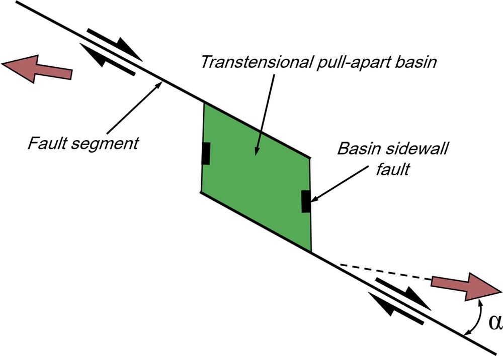
Transtensional basins form under strike-slip conditions in an extensional environment (Fig. Sm1 in supplementary material), while transpressional basins form under strike-slip conditions in a compressional environment; both types are categorized as strike-slip or stepover basins (Ingersoll, 2012; Misra and Mukherjee, 2016; Nilsen and Sylvester, 1999; Ramsay and Huber, 1987; Sylvester, 1988; Talbot et al., 2009). Extensional settings can be categorized into orthogonal or oblique extension groups, based on the intersection angle between the pre-existing basement fault and the tensional stress direction. An oblique extensional basin forms when the strike directions of the reactivated basement faults cross the regional extensional direction at an oblique angle, and the boundary faults behave as normal faults with strike-slip features (Fossen et al., 2013; Manighetti et al., 2001a; Misra and Mukherjee, 2016). Different fault segments accommodate oblique faulting (strike-slip and normal displacements) within the transtensional pull-apart basin, which results in complex fault zone geometry, formation of valleys, and rotations along the fault systems (e.g., Chemenda et al., 2016 Manighetti et al., 2001a; Mart and Vachtman, 2015). Many continental rift margins undergo strike-slip controlled deformation associated with transtension and/or transpression basins (Dasgupta and Mukherjee, 2016; Misra and Mukherjee, 2016; Nemčok, 2016).
Pull-apart structures are depressions that form at releasing bends and steps in basement strike-slip fault systems. Pull-apart structures are generally inferred to occur as basins (Gürbüz, 2010; Misra and Mukherjee, 2016), although centimeter-scale veins (Peacock and Sanderson, 1995a, 1995b), region-scale plutons (Tikoff and Teyssier, 1992), and regional-scale blueschist massifs (Mann, 2007) are also inferred to fill these structural “holes” (Aydin and Nur, 1985). Traditional models of pull-apart basins usually show a rhombohedral (Talbot and Alavi, 1996) (e.g., Dead Sea basin) to spindle-shaped (e.g., Death Valley basin) depression between two parallel master vertical strike-slip fault segments (Mann, 2007; Mann et al., 1983; Ramsay and Huber, 1987). The basin is bounded longitudinally by a transverse system of oblique-extensional faults, termed “basin sidewall faults” (cf. Fig. Sm1 in supplementary material) that link with the bounding principal deformation zones (Dooley and Schreurs, 2012; Gürbüz, 2010; Waldron, 2005; Wu et al., 2009). Depending on the assumed fault plane orientation with respect to the oblique far-field stress, the extensional and contractional steps may be classified as either “transtension” or “transpression”, respectively. Transtension (and transpression) zones result in a combination of simple- and lateral extensional pure-shear components with vertical depression (Dewey, 2002; De Paola et al., 2005; Fossen and Tikoff, 1998; Fossen et al., 1994; Sanderson and Marchini, 1984). Hence, transpression zones can be related to the boundary conditions and obliquity between the imposed compressive stress and plate boundaries (Díaz-Azpiroz et al., 2016; Frehner, 2016; Nabavi et al., 2017b, 2017c). Pull-apart basins that have developed with transtensional displacement are of significant economic importance and can contain zones of intense fracturing, giant hydrocarbon fields, mineralization, and geothermal fields (Dasgupta and Mukherjee, 2016; Dewey, 2002; Peacock and Anderson, 2012).
Numerical techniques, especially the finite-element (FE) method, are powerful to provide comprehensive insight beyond the direct observations, such as the stress state, strain and deformation patterns during and after the structural evolution. Mechanical modelling of a fault step avoids many common assumptions, for example homogeneous deformation, inherent to kinematic models (Nevitt et al., 2014). Mechanical analyses identified certain basic variables that influence the evolution of transtensional deformation in extensional fault steps, such as the fault overlap-to-separation ratio and the relative orientation of faults. The mechanical interaction between fault segments helps rationalize the overlap-to-separation ratio, to understand why some fractures/faults selectively terminate whereas, others propagate, and to understand why some faults deviate systematically from symmetric slip distributions (Lejri et al., 2015; Manighetti et al., 2001b; Strijker et al., 2013). The static sliding friction coefficient strongly affects the fault mechanical properties and local stress field (Maerten et al., 2016; Soliva et al., 2010).
Here, we use a series of 2D FE elastic models through ABAQUS™ software package to simulate stress and strain features recorded in a transtension zone within a straight and parallel extensional fault step. The strike-slip fault segments (also called master faults) can underlap, have a neutral configuration, or overlap. All of such step geometries form naturally and are found in nature (Cunningham and Mann, 2007). It is well known that fault step geometries affect the shape and structure of pull-apart basins between the fault segments, but the reasons are not fully understood. To approach them, we simulate the range of various divergence angles (30°, 45° and 60°) under different fault step geometries such as underlapping, neutral and overlapping releasing fault step geometry, and analyze the stress/strain fields by applying different sets of boundary conditions. The purposes of this study are:
- • to understand the role of frictional strike-slip fault separation and amount of overlap on the development and evolution of transtension zones;
- • to predict the possible fault pattern inside the transtension zone;
- • to describe the stress distribution and strain localization patterns;
- • and to predict the shape of the transtensional pull-apart basin.
We eventually compare our results to previous analogue (e.g., Dooley et al., 2004; Wu et al., 2009) and numerical models (e.g., Newitt et al., 2014; Strijker et al., 2013), which are complementary to the methods used here. Despite the limitations of our simple model (2D and elastic), we provide first-order insights that might be useful to better understand pull-apart formation and evolution.
2 FE-model procedure
2D planar strain and linear elastic solid behavior (linear relation between stress and strain) is adopted for FE-modelling of transtension. The focus is on the interactions between two parallel vertical and, planar right-stepping right-lateral/dextral strike-slip faults with equal lengths (a releasing step) that obey the Coulomb criterion for fault slip (Fig. 1). Friction along the fault segments is constrained by a coefficient of 0.3–0.6 (Byerlee, 1978). In the present study, the value 0.51 is retained for the sliding friction of (assuming cohesiveless material) sandstones (Pollard and Fletcher, 2005). Sliding occurs if traction on the fault exceeds 0.51 of the normal stress (Byerlee, 1978). The pair of fault segments strike obliquely to the direction of tensional normal stress applied to the model boundaries. The fault segments have a left-oblique component (Crider, 2001) that creates right-lateral movement/offset/slip. Surrounding the faults, we assume an isotropic homogenous linear elastic material. Thus, the model is a crude simplification of actual faults, which are generally surrounded by damage rocks (e.g., Perrin et al., 2016, and references therein). Yet, one reason for studying the elastic behavior is that the upper part of the lithosphere is often approximated as an elastic material (Turcotte and Schubert, 2014). Other studies indicate that the rheology of the upper crust is elastic-plastic (e.g., Prezzi et al., 2009; Thompson and Parsons, 2009). Nevertheless, because the rheology is approximate, we use the elastic models to only investigate spatial patterns and relative amplitudes of deformation. Our analysis is thus a linear approximation of a non-linear process. Therefore, we do not attempt to predict absolute uplift, subsidence, or slip along faults, but only a relative pattern of deformation.
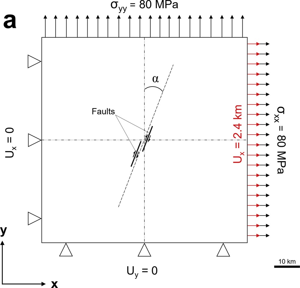
The general model set-up with two fault segments and boundary conditions. The finite element shown in the faults are pre-defined to strike at α = 30, 45 and 60° in a clockwise sense from the Y-axis, where α is the divergence angle.
The 2D FE-model considers plane strain, which is valid if the faults are much longer in the Z-direction than in the X- and Y-directions. The effects of topography and crust curvature are ignored. To avoid the effects of model boundary on stress distribution, the model dimensions are significantly larger (≥ 5 times) than the dimensions of the fault system (Misra et al., 2009), so that the applied boundary conditions simulate a far-field stress. A total of 23,819 quad-dominant isotropic brick elements (23,834 nodes) and two master right-lateral strike-slip faults describe a model of 80 × 80 km. Each fault segment is 10 km in length. The size of the elements decreases from the boundaries towards the faults to ensure sufficient accuracy, whilst limiting computation time (Fig. 1b).
The used elastic parameters are as follow: Young's modulus (E), 22 GPa and Poisson's ratio (ν), 0.24 (based on Jaeger et al., 2007; Pollard and Fletcher, 2005). The elastic modelling parameters are kept constant for all experiments at physically realistic material property mean values representative for sandstones (Jaeger et al., 2007; Pollard and Fletcher, 2005)). Previous numerical studies have shown that changing the elastic parameters does not produce significant changes in the modelling results (Bertoluzza and Perotti, 1997; Gölke et al., 1994). A tensional normal stress is applied to two adjacent boundaries of the model with a maximum value of 80 MPa based on Strijker et al. (2013). In addition, a displacement boundary condition is introduced on the right boundary of the model to produce a bulk shortening of 3% across the model. Lower and left boundaries of the model domain is constrained by the condition that uy = 0 and ux = 0, to prevent rigid body rotation and translation during loading (Nevitt et al., 2014) (Fig. 1a). These boundary conditions define shear planes, both parallel to the fault steps and parallel to internal faults (Westaway, 1995), which obliquely connect fault steps.
We use a right-stepping configuration of two right-lateral faults to quantify the effect of different step geometries on the stress and strain distribution throughout the model. The faults are pre-defined to strike at α = 30, 45, and 60 in a clockwise sense from the Y-axis, where α is the divergence angle (assuming that modelling was monitored through a top view) (Fig. 1). The main parameters investigated in the current model series are the divergence angle, the angle of offset between the master fault segments and the step geometries. In the present study, transtension is considered in different overlap-to-separation situations such as underlap, neutral, and overlap. Growth of the pre-defined faults is not considered; instead we focus on the resulting stress and strain distribution as indicators for the potential development of subsequent fractures/faults. Overlap (O) and underlap (U) are measured from fault tip to fault tip, parallel to the main fault strike. Separation (S) is measured orthogonal to the main fault strike (Corti and Dooley, 2015; Dooley and Schreurs, 2012; McClay and Bonora, 2001). ‘S’ is 12.5% of the length of the fault segments (i.e. 1.25 km). Underlap and overlap are 25% of the length of the fault segments (i.e. 2.5 km). Thus, the overlap-to-separation ratio is 2:1. In addition, the step geometries are at 26° in case of underlapping step, 90° for neutral step and 154° for the overlapping step (Fig. 2). These angles are measured between the strike of the main fault segments and the line jointing the tips of the faults in the step zone. All other parameters, including the separation between the master fault segments and the initial width of the offset area/weak zone (i.e. overlap and underlap size) are kept constant.
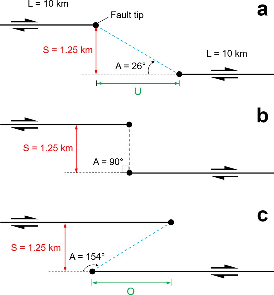
Separation and angular relationships of the steps for the three models presented in this study (after Corti and Dooley, 2015; Dooley and McClay, 1997): 26° underlapping 90°, neutral and 154° overlapping steps. The angles of the steps are identical in numerical models. Separation (S) is 12.5% of the length of the fault segments. Overlap (O) and underlap (U) are 25% of the length of the fault segments. Underlap and overlap are measured from fault tip to fault tip, parallel to the master fault strike. Separation is measured orthogonal to the master fault trend.
3 Results
In many ways, the stress development in an evolving transtension zone within an extensional fault step mirrors that of a transpression zone within contractional fault steps.
Mean normal stress is obtained for underlapping (see supplementary Fig. Sm2a–c), neutral (see supplementary Fig. Sm2d–f), and overlapping (see supplementary Fig. Sm2g–i) fault steps. Elastic modelling shows that the mean normal stress within the step is tensional (see supplementary Fig. Sm2d-i), while the region outside the step is characterized by compressive mean normal stress. The mean normal stress pattern is characterized by a regional minimum, localized inside the extensional step (transtension zone), and two local maximum and minimum couples, formed at the advancing and retreating sides, respectively, in the fault segment tips. The mean stress effectively shows uplift (contraction) and subsidence (extension) associated with faulting (Aydin and Schultz, 1990; Brankman and Aydin, 2004). In the overlapping fault steps for all divergence angles, model results show relatively high mean stresses to localize at fault tips and decreasing towards the central portions of the zone as the two segments interact (supplementary Fig. Sm2g–i). In neutral configurations, mean stresses localize more at fault tips than at the overlapping steps (supplementary Fig. Sm2d–f). In contrast, for underlapping fault steps for all divergence angles, there is a concentrated slightly high mean stress between the segments (supplementary Fig. Sm2a–c). However, the uplift near the tips of overlapping fault segments is small relative to the subsidence of the basin. In addition, in all models, there form two main subsidence zones (depocenters or sub-basins) along and in the proximity of the fault segments tips that are separated by a broad zone of relative uplift that strikes oblique to the fault segments. This uplift is less developed in neutral and overlapping steps (as a large area of subsidence) than the underlapping steps. In other words, the depth and development of the depocenters increase due to fault interaction.
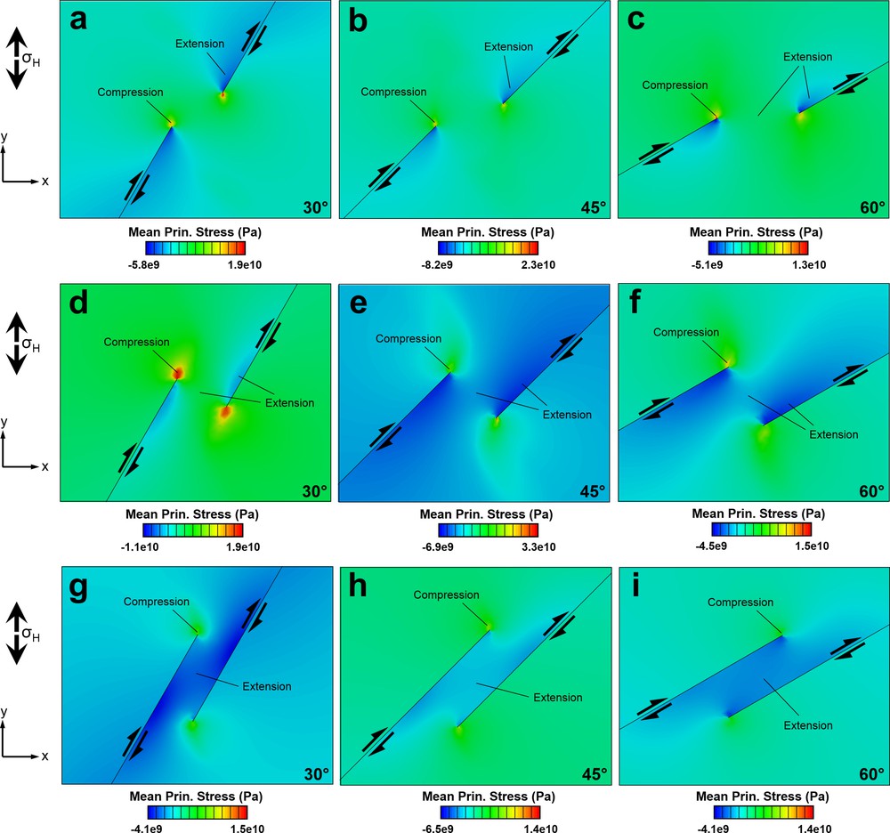
The modelled minimum principal compressive stress (σ3) progressively rotates towards parallelism with the boundary fault segments as the oblique divergence angle increases from 30° to 60° (Fig. 3). In all models, the mean stress maximums are greater than differential stress (σ1–σ3). The results show that the tensional quadrants of the inner fault segment tips are located inside the relay zone, resulting in a relatively low σ3 zone in this area for the majority of models, unlike the transpression zone with the contractional fault step (Nabavi et al., 2016, 2017a). In the overlapping fault step, wing and horsetail faults are expected to develop aligned with the orientation of the maximum principal stress (σ1), outwards from the outer fault tips and into the relay zone from the inner fault tips (Fig. 3g–i).
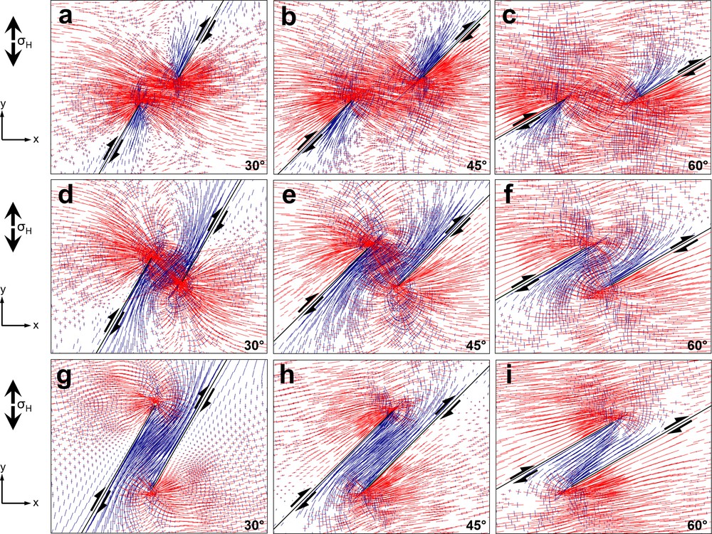
Model with maximum (red) and minimum (blue) principal stress orientations for an underlapping fault step (a–c), a neutral fault steps (d–f), and an overlapping fault step (g–i) under divergence angles of 30°, 45° and 60°. Maximum and minimum principal stresses align with compression and extension direction, respectively.
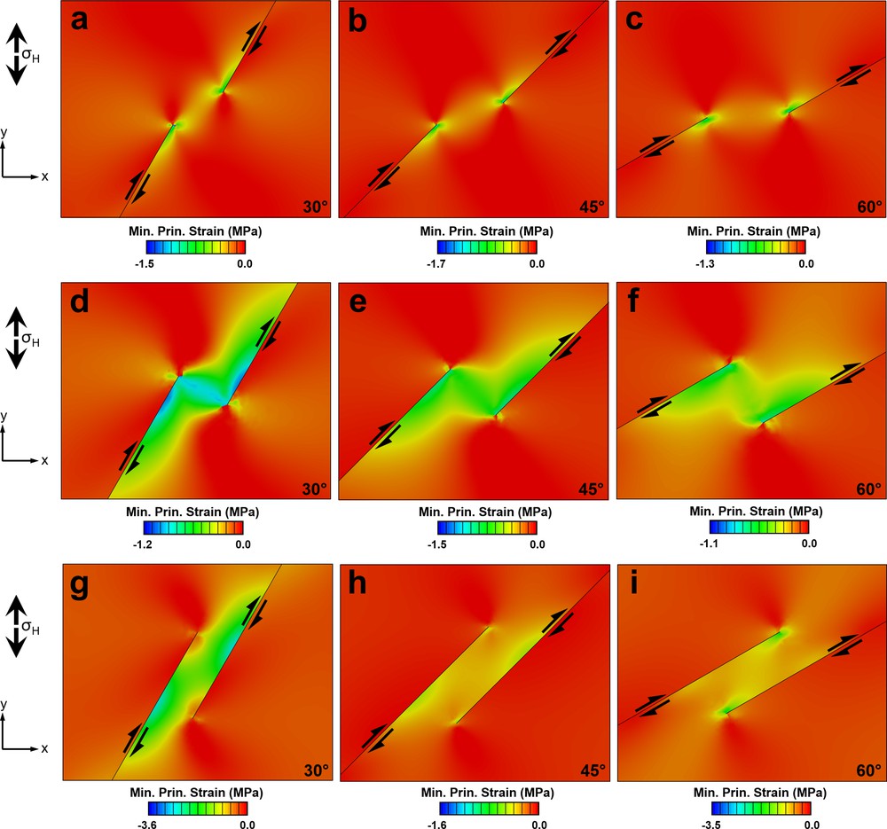
The strain patterns in our reference models are demonstrated by a series of snapshots in Fig. Sm3 in supplementary material. Generally, deformation (transtension) starts to localize in the region where the faults overlap. All models have relatively low shear strains and no apparent differences in shear strain are found at the inner and outer sides of fault segments and in the transtension zone. Moreover, shear strain increases at fault tips with a slight increase outside the transtension zone, while for the transpression zones the shear strain increases with the contractional fault step (Nabavi et al., 2017a, 2018). These features for the transtension zones and extensional fault steps are greatly different from those for the transpression zones and compressional fault steps.
In all present models, strain and stress trajectories rotation and variation in stress and strain magnitudes reflect a heterogeneous deformation. In other words, strain localization occurs in all models. In addition, the stretch ellipsoid (the amount of strain components after mapping all of them) varies in orientation across the step, showing a heterogeneous deformation. The results suggest that, even when the major faults are compressed orthogonally and the overall deformation is plane strain, transpression zones can be involved by a complex three-dimensional stress/strain field inconsistent with the regional strain field.
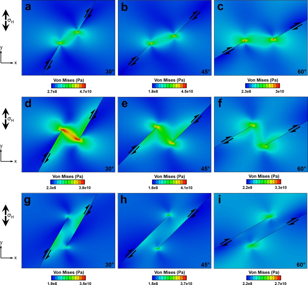
The Von Mises equivalent stress (a function of the principal stress difference and the maximum shear stress) distribution in the transtension zone is different from the outside zone. This modification of the stress field is more prominent in the case of overlapping steps than in the case of neutral and underlapping steps. In almost all configurations (see Fig. Sm4 in supplementary material), lobes of enhanced Von Mises equivalent stress extend beyond the fault tips and slightly beyond the fault segments. In general, underlapping (see supplementary Fig. Sm4a–c) and neutral (see supplementary Fig. Sm4d-f) fault steps result in higher distortional stresses/strains at fault tips than in the case of overlapping faults (see supplementary Fig. Sm4g-i), characterized by lower Von Mises stress in the transtension zone.
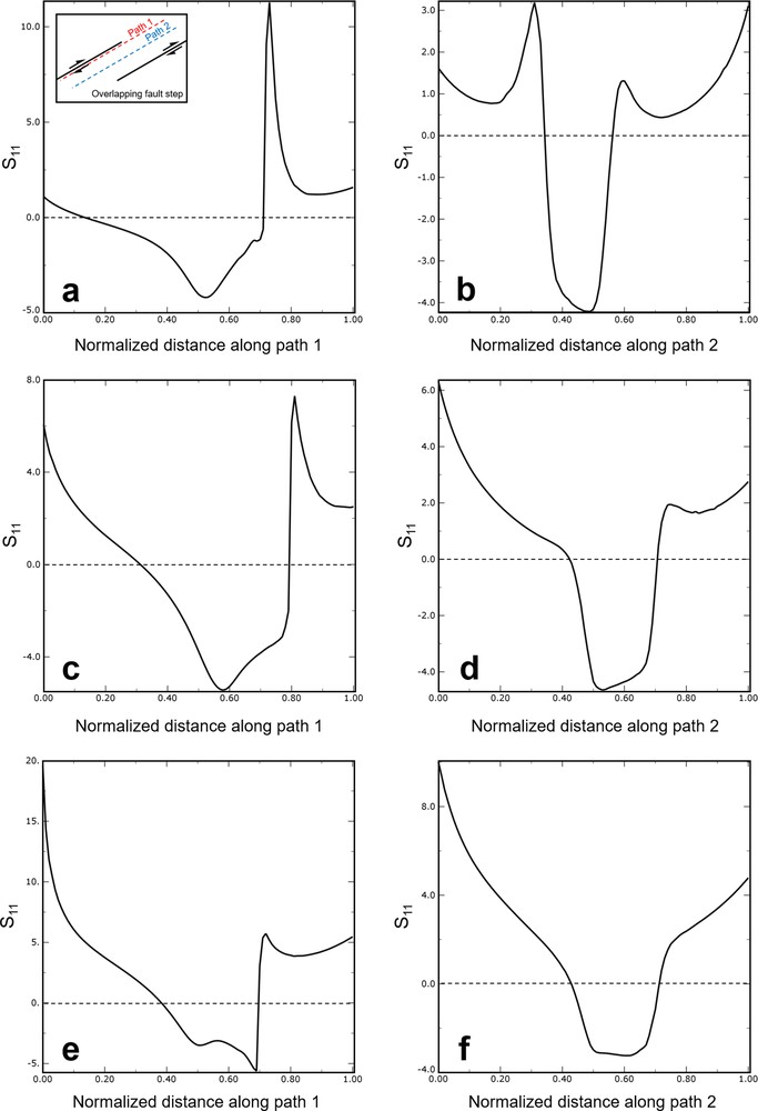
Figs. Sm5 in supplementary material present data collected along two transects through the overlapping fault step models for divergence angles 30 (see Fig. Sm5a, b in supplementary material), 45 (see Fig. Sm5c, d in supplementary material) and 60° (see Fig. Sm5e, f in supplementary material). Transects 1 and 2 are parallel to the fault segments. The first profile is near the zone boundary, and the second passes through the centre of the zone. The two transects record very different profiles of the principal stretch (S1) magnitudes. Transect 1 demonstrates that in the direction parallel and adjacent to the step-bounding faults, the stretch is strongly asymmetric and focused into the step region, so that stretch difference increases with increasing the divergence angle. On the other hand, transect 2 shows that asymmetry and difference of stretch within and out of fault step is less than along transect 1. The size and shape of areas of general extension are controlled by the overlap/separation ratio of the fault segments as well as the boundary conditions. Generally, the areas of extension increase as the overlap/separation ratio increase.
4 Discussion
Our results show that the shape and number of depocenters that are formed vary with the geometry of the fault step and the obliquity of the divergence angle. With less underlap (from underlapping step toward neutral step), dual depocenters connect and with increasing overlap a single transtensional pull-apart basin develops with a central deep. Overall, transtensional pull-apart basin models produced connected depocenters with basin high and lozenge shape for underlapping fault steps (Fig. 4a), spindle shape or lazy S or Z shape for neutral fault steps (Fig. 4b), and hour-glass (Fig. 4c) to broadly elongate rhomboidal to sigmoidal basins for overlapping fault steps (Fig. 4d, e), with en-échelon oblique-extensional sidewall faults that hard- and soft-linked (Peacock et al., 2016) to form an arcuate trace in two dimensional state and plane view. This geometry is similar to many pull-apart basins (e.g., Aydin and Nur, 1985; Manighetti et al., 2001a; Mann, 2007) and previous analogue models of pull-apart basins (e.g., Corti and Dooley, 2015; Dooley and McClay, 1997; Dooley et al., 2004; Mitra and Paul, 2011; Sugan et al., 2014; Wang et al., 2017; Wu et al., 2009). The Mesquite Basin in California, formed where the Brawley and Imperial dextral strike-slip faults created neutral steps, is an example of a spindle-shaped pull-apart basin (e.g., Dooley and McClay, 1997). The Gulf of Aqaba basin and the Dead Sea basin that located along the African-Arabian plate boundary, are examples of an hour-glass-shaped and rhomboidal-shaped basin, respectively, along the overlapping fault step (e.g., ten Brink et al., 1996; Wu et al., 2009). This transition of basin shapes from underlapping to overlapping steps is accompanied by increasing curvatures in the faults within the transtensional pull-apart basin.
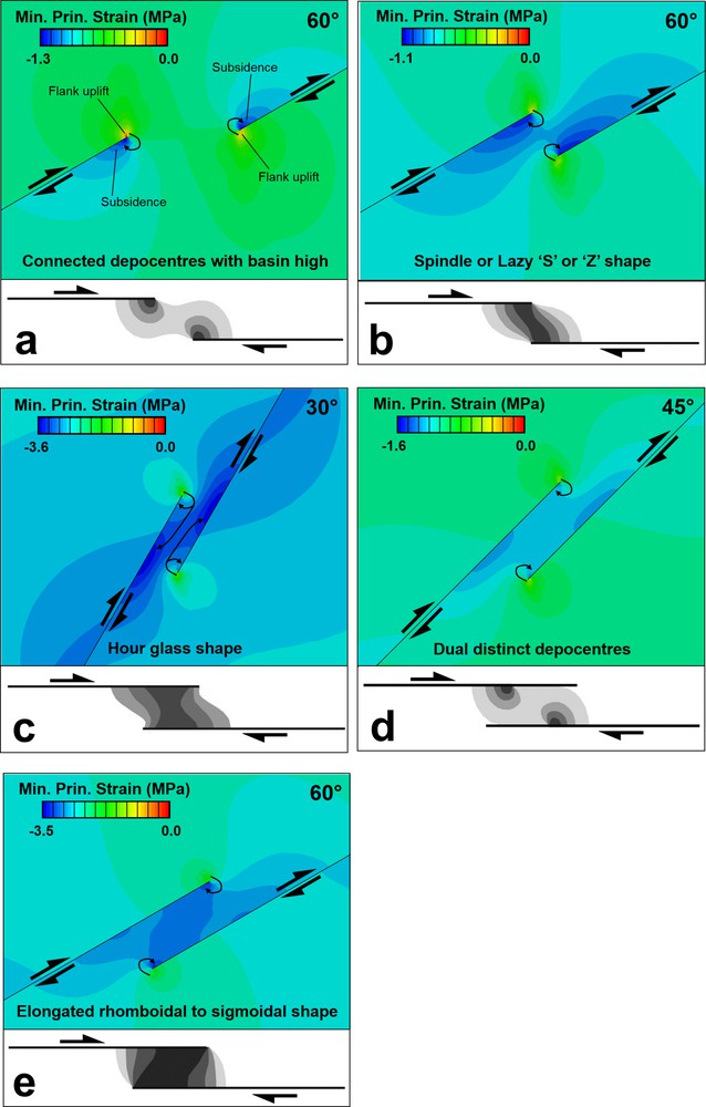
Schematic shapes of observed transtensional pull-apart basin geometries (modified after Mann, 2007; Mann et al., 1983) with mean principal stress results from this study. Arrows indicate the sense of shear. The geometry of fault segment is indicated in each part with thick black lines. Shading shows transtensional pull-apart basin subsidence, with darker shades of grey indicating larger amounts of subsidence. Blue colors indicate subsidence in the transtensional pull-apart basin; red to bright green colors in fault segments tips indicate basin flank uplift (sedimentary source areas). Basin subsidence increases and the transtension pull-apart basin lengthens as the fault segments’ overlap increases. Possible sediment transport directions are indicated with curved black arrows.
Transtensional models developed dual asymmetric depocenters at opposite ends of the basin that were separated by a relative uplift or intrabasin horst structures, while pure strike-slip pull-apart basin developed a single central depocenter (Corti and Dooley, 2015; van Wijk et al., 2017; Wu et al., 2009). The geometry and location of these intrabasin structural highs are dependent on the imposed boundary conditions and fault steps geometries (Anders and Schlische, 1994). The region of structural uplift develops outside the transtension zone and the fault tips. The mean stress distribution results (Fig. Sm2 in supplementary material) show that the greatest basin subsidence is observed for neutral step geometry and in the area where the fault segment tips interact. Basin flank uplift is predicted in all models (e.g., Dooley and McClay, 1997; Katzman et al., 1995; ten Brink et al., 1996; van Wijk et al., 2017). This uplift occurs along the shoulders of the entire transtensional basin. The model results predict maximum uplift amplitudes for underlapping steps, and basin flank uplift decreases with increasing fault overlap distances.
Generally, en-échelon basin margin system, dual asymmetric opposing depocenter, intrabasin relative structural high, asymmetric negative flower structure (in 3D models) (e.g., Feng and Ye, 2017; Nilsen and Sylvester, 1999; Sugan et al., 2014; van Wijk et al., 2017; Wang et al., 2017; Wu et al., 2009) and wide basin width can be used as indicators that a pull-apart basin is developing in transtension zones. Although new faults do not form in these models due to continuum nature of finite element method, we can infer from the modelling results that accommodation of extension in the transtensional pull-apart basin is related to new transverse normal faults that would form within the transtension zone, especially intrabasinal normal faults sub-perpendicular to the fault segments (Anders and Schlische, 1994). The different shapes of the transtensional pull-apart basins are controlled by various parameters, such as fault step geometries, overlap-to-separation ratio, oblique divergence angle, rheology, thickness (e.g., Jayko and Bursik, 2012; van Wijk et al., 2017; Wu et al., 2009). In some cases, different shapes of the transtensional pull-apart basins are developed as the oblique divergence changes. For example, the models showed that elongated rhomboidal-shaped basins (in the case of the overlapping step and in oblique divergence 60°) evolved from the following stages:
- • connected structural high;
- • dual distinct asymmetric depocenters;
- • spindle-shaped basins,
- • sigmoidal basin;
- • elongated rhomboidal shape.
An important advantage of numerical models in the comprehension of geological structures is that they allow one to follow the evolution of deformation and stress fields (e.g., Nemčok et al., 2002; Peacock and Zhang, 1994; Pollard and Aydin, 1988). The stress and strain fields that develop at the fault segments tips and along them control further the opening of the transtensional pull-apart basin. The stress and strain distributions from underlapping steps to overlapping steps reveal that the transtension zone within extensional fault steps locally accommodates the regional stress field. In an underlapping fault step, stress and strain are distributed throughout the block region outside of the transtension zone because the fault-parallel block motion is not accommodated by strike-slip fault segments in the underlapping step. In contrast, in neutral and overlapping fault steps, the two blocks move coherently in the direction of relative block motions and stress and strain are concentrated in the transtension zone. Such stress concentration in overlapping transtension zone could connect secondary strike-slip faults/fractures that initiate at one fault tip to the other fault to form basin-crossing faults (geometrically coupled fault/fracture segments) (Peacock et al., 2017a, 2018). Because our models do not allow for new faults to form, these zones concentrate stress and strain in our models (kinematically coupled fault/fracture segments) (Peacock et al., 2017a, 2018), but do not develop into basin-crossing faults. Minimum principal stress, along which basin-crossing faults may form, connects the fault segment tips in underlapping steps (Fig. 3a–c) and may connect behind the fault segment tips in neutral steps (Fig. 3d–f). Extension parallel to the fault segments occur in overlapping steps (Fig. 3g–i). Furthermore, note that the basin-crossing faults in the overlapping steps are less developed than in the underlapping and neutral fault steps. According to Fig. 3g–i, minimum principal stresses, along which basin-crossing faults may form, are much less developed in the overlapping step. Hence, basin-crossing faults are not developed there.
The results suggest that even for an isotropic material, fault interactions result in non-coaxial strain paths and complex stress fields within the transtension zones. Due to these fields, secondary faults (or fractures), wing cracks and horsetail fracture arrays (as off-fault splay networks) (Perrin et al., 2016) develop near the tip of the fault segments. Wing cracks are formed in the dilational quadrant of a mode-II fracture and follow the trajectories of the maximum principal compressional stresses (e.g., Peacock and Anderson, 2012; Pollard and Segall, 1987; Segall and Pollard, 1980; Vermilye and Scholz, 1998). At the tips of mode-II cracks or strike-slip faults, the local perturbation of the main stress field causes splay faults to occupy three distinct domains dominated respectively by shear, contractional and extensional structures (McGrath and Davison, 1995; Maerten et al., 2002). This is because the depth of the faults is relatively short with respect to the model's dimensions. Altering the strike of the fault segments relative to the direction of the imposed boundary conditions alters the geometry of linkage, because the symmetry of the system changes (e.g., Gölke et al., 1994; Nabavi et al., 2017a).
5 Conclusions
Stress distribution and strain localization patterns were obtained for a set of 2D finite element models of transtensional pull-apart basins related to two pre-existing right-stepping right-lateral fault segments as a function of the remotely applied compressive stress. In each simulation, different divergence angles (α), i.e. 30°, 45° and 60°, were applied to the three representative end-member fault segment interaction models, which are underlapping, neutral and overlapping steps. The models show that the evolution of transtensional pull-apart basins is controlled by the initial fault step geometries, overlap-to-separation ratio and oblique divergence angle.
The modelling results suggest that the angle of offset between the fault segments is one of the most important parameters controlling the geometry of transtensional pull-apart basins: connected depocenters with basin high and lozenge shape in the case of underlapping fault steps, spindle shape or lazy S or Z shape in the case of neutral fault steps, and broadly elongate rhomboidal to sigmoidal basins in the case of overlapping fault steps. The geometry and location of intrabasin structural highs, and basin asymmetry are dependent on the imposed boundary conditions (oblique divergent motion) and fault steps geometries.
Acknowledgements
We greatly thank Prof. Christopher J. Talbot and Prof. David C. P. Peacock for their careful and constructive reviews, comments and suggestions that improved the earlier version of this manuscript. We thank reviewers Dr. Alexandre I. Chemenda and Dr. Jonny E. Wu for their attentive reading and constructive comments, which improved the manuscript. Editorial handling work by Prof. Isabelle Manighetti is also gratefully acknowledged.
Appendix A Supplementary data