

1 Introduction
Nanoscience and nanotechnology have attracted numerous research interests in the past few decades because nanostructured materials were noted to exhibit exclusive properties as compared with their bulk counterparts [1–3]. Nanostructured materials show novel optical, electronic, and magnetic properties because of the finite surface effect, size effect, and macroscopic quantum tunneling effect at nanodimension. Hence, nanostructured materials unveil an extensive sort of applications in the development of catalysts, fuel cells, gas sensors, photoelectronic devices, energy storage devices, super capacitors, and lithium-ion batteries [4–7]. At present, production of fine nanopowders with superior quality in terms of size, morphology, and structure is a research title of great interest. Different methodologies to fabricate nanosized materials were proposed such as solvothermal synthesis [8,9], carbonyl and pulsed laser ablation, microwave irradiation [10], microemulsion [11,12], sonochemistry [13], ultrasonic radiation [14], anodic arc plasma method [15,16], coprecipitation [17], and sol–gel methods [18–20].
An important advantage of the coprecipitation method is the capability to control the physicochemical properties of nanopowders by varying the synthesis parameters without using any sophisticated equipment or expensive chemical reagents. Nanostructured nickel based materials were commonly studied in catalysis because of their relatively low cost, low toxicity, superior activity, stability, and environmentally friendly characteristics [17,21,22]. Furthermore, nickel-based nanomaterials were also used in the development of numerous materials other than catalysts such as electrochromic materials [23], p–n heterojunctions [24], gas sensors [25–27], magnetic materials [28], optical materials [29], fuel cell electrodes [30], batteries [31], electrochemical capacitors [32], and solar cells [33,34]. Coprecipitation cum modified Stöber method was adopted in the present study to produce nano-nickel catalysts with crystal sizes of ∼30 nm supported on silicate [17]. The synthesized silicate-supported nickel catalysts were used in methane decomposition in which methane conversion activity and stability were subsequently evaluated. Methane decomposition results in the simultaneous production of two desired products, which are hydrogen and nanocarbons as shown in Eq. 1. Hydrogen and nanocarbons are among the most emergent products in the field of ecofriendly energy and material science, respectively.
| CH4 → C + 2H2 ΔH298K = 74.52 kJ mol−1 | (1) |
Hydrogen can be considered as a potential energy carrier in the current scenario of substantial depletion of fossil fuel resources and deterioration of ecological environment because of high greenhouse gas emission [35]. Hydrogen performs a vital function in addressing the current energy crisis mainly because of its zero greenhouse gas emission during combustion, as shown in Eq. 2 [36]:
| H2 + ½O2 → H2O ΔH298K = −285.83 kJ mol−1 | (2) |
Furthermore, hydrogen can be produced from renewable raw materials such as water, biomass, and biogas [37,38]. The fully green methane decomposition technology can be considered as a sustainable approach for the production of hydrogen, because methane is the major component of biomass and large methane reserves are accessible in the deep ocean bed and in industrialized countries [21,39]. Hence, automobile industries, science laboratories, and governments have focused more on the application of hydrogen as a possible alternative fuel to simplify both widespread production and distribution.
The implementation of catalysts in methane decomposition is essential because of the high temperature requirement such as 1200 °C for the scission of strong CH bond to achieve a rational hydrogen and carbon yield [40]. Hence, CH4 molecule is highly stable with tetrahedral geometrical structure supported with four extremely strong CH bonds with bond energy of 434 kJ mol−1. The effectiveness of a catalyst is not only constrained to higher methane decomposition rate and conversion at low temperature but also the capability to produce large amounts of nanocarbon while preserving the thermochemical stability of the catalyst. Accordingly, various metal and carbon-based catalysts were introduced [41,42]. Literature survey revealed that metal catalysts exhibited high catalytic activity and high initial methane decomposition rate but deactivate drastically over time [21,41]. On the other hand, carbon-based catalysts and metal-doped carbon catalysts preserved superior stability with a lower deactivation rate than that of metal catalysts. Nevertheless, these catalysts exhibited poor methane conversion in spite of their higher stability. Our previous studies showed that the performance of the Ni/SiO2 nanocatalyst in terms of its stability and activity for methane decomposition is superior to that of Co/SiO2 and Fe/SiO2 nanocatalysts [43,44].
The activity, stability, and selectivity of the catalyst are evidently dependent on the material composition, production parameters, synthesis method, and methane decomposition operating conditions. The introduction of a highly stable catalyst that exhibits higher methane conversion at lower temperature amid huge carbon deposition is obligatory for the establishment of hydrogen production technology from a methane source at the industrial scale. The characteristics of the catalyst and experimental parameters directly influence the stability and activity. For instance, the electronic state of the metal particles (which depends on metal and support interaction), crystallinity, crystalline size, dispersion of metal particles, textural properties and pore geometry [45], catalyst composition [46], calcination and reduction temperature [47,48], catalyst preparation method [49], and catalyst rinsing solvent [50] are some of the major factors which affect the catalyst stability.
The precise structural and functional control for both metal and silicate support were achieved by changing the precursor ratios. Porosity of the catalyst support directly influences the total surface area and catalyst dispersion, resulting in distinctive catalytic properties. In general, catalyst porosity management is accomplished by changing surfactants, soft templates, additives, and reaction conditions [51,52]. However, we have accomplished porous regulation by changing the quantity of octadecyltrimethoxysilane (C18TMS) porogen with respect to silica precursor (tetraethylorthosilicate, TEOS). C18TMS produces heterogeneous domains and leads to the development of large quantity of pores inside the silica structure on thermal treatment [53]. Furthermore, we studied the influence of the concentration of a raw material solution and the type of a solvent on the characteristic properties of the produced nanocatalyst. To the best of the authors' knowledge, this study is the first to deal with the governance of characteristic and catalytic properties of the nano-NiO/SiO2 (n-NiO/SiO2) nanocatalyst by varying the synthesis parameters in the coprecipitation cum modified Stöber method. Regardless of traditional approaches, coprecipitation cum modified Stöber method offers numerous advantages such as easy scale-up to gram quantities, usage of environmentally friendly precursors and solvents, usage of cost effective chemicals, formation of smaller crystalline nanoparticles, high reproducibility, avoidance of surfactants, and evasion of tedious purification procedures.
In this article, we studied the influence of different nanomaterial preparation parameters on porosity, crystal structure, morphology, elemental composition, and metal–support interaction by means of characterization methods such as N2 adsorption–desorption measurement (Brunauer–Emmett–Teller, BET), X-ray diffraction (XRD), hydrogen-temperature–programmed reduction (H2-TPR), field-emission scanning electron microscopy (FESEM), energy-dispersive X-ray spectroscopy (EDX), and transmission electron microscopy (TEM). The catalytic performance of prepared n-NiO/SiO2 catalysts was evaluated by conducting thermocatalytic decomposition (TCD) of methane in a fixed catalyst bed reactor.
2 Experimental section
Coprecipitation cum modified Stöber method was adopted for synthesizing a fine nanopowder nickel supported on silicate [17,54]. First, an aqueous solution of nickel (II) nitrate hexahydrate (Ni(NO3)2·6H2O) was converted to the corresponding hydroxide by treatment with ammonia solution under atmospheric condition. The development of silicate support was done through the hydrolysis of a mixture of TEOS and C18TMS with ammonia solution in the suspension of nanometal hydroxide in different solvents. The influence of different metal/silicate ratio, TEOS/C18TMS ratio, and different solvents on the characteristics and catalytic behavior of the produced nanomaterials were examined.
2.1 Chemicals used
Ni(NO3)2·6H2O and C18TMS were bought from Acros Organics. Aldrich provided TEOS. Ammonia solution, methanol, ethanol, 2-propanol, and n-butanol solvents were sourced from R&M Solutions. All purchased chemicals were used without any further purification. Linde Malaysia Sdn. Bhd supplied hydrogen (99.999%), methane (99.995%), and nitrogen (99.99%) gases for conducting catalytic activity examination.
2.2 Preparation of n-NiO/SiO2 catalyst
Nanosized nickel hydroxide was prepared by the coprecipitation method. An appropriate amount of Ni(NO3)2·6H2O was accurately weighed and dissolved in 200 mL of deionized water under sonication. The quantity of each substrate for the production of nanocatalysts and the corresponding naming are furnished in Table 1. Twenty milliliters of 30% ammonia solution was added dropwise to precipitate Ni(OH)2. Precipitation was completed by 1 h of sonication. The temperature increase during sonication was controlled using an ice bath. Consequently, the resulting Ni(OH)2 suspension was magnetically stirred for another 1 h at room temperature. After that nanosized Ni(OH)2 was separated by centrifugation at 4000 rpm for 30 min and washed twice with water and once with the corresponding solvent, as indicated in Table 1. Then, the separated product was dispersed in 100 mL of the corresponding solvent and stirred constantly for 15 h with magnet. Successively, 4 mL of 8 M ammonia solution was added to the dispersion under sonication. Appropriate quantities of TEOS and C18TMS were simultaneously added to the basic dispersion under sonication to form silicate support to guard the active metal phase, and this approach is called modified Stöber method. Sonication was further continued for 1 h, and the reaction mixture was stirred with a magnet for another 5 h. After that n-Ni(OH)2/SiO2 precipitate was separated by centrifugation and dried in an oven at 100 °C for 15 h. Dried n-Ni(OH)2/SiO2 precipitate was calcined at 450 °C in a programmable furnace at the rate of 10 °C/min and allowed to stay for 3 h. Calcination converted the hydroxide to n-NiO/SiO2. Finally, n-NiO/SiO2 nanocatalysts were reduced to n-Ni/SiO2 by treating with 30% H2 for 2.5 h at 550 °C, immediately before activity examination in the methane decomposition unit. The simplified schematic of catalyst preparation is shown in Scheme 1.
Quantity of each substrate and the solvents used for the production of n-NiO/SiO2.
| No. | Nanocatalyst | Ni(NO3)2·6H2O (g) | TEOS (mL) | C18TMS (mL) | Solvent |
| 1 | n-NiO/SiO2_(1) | 5.81 | 0.3 | 0.3 | Ethanol |
| 2 | n-NiO/SiO2_(2) | 11.63 | 0.6 | 0.6 | Ethanol |
| 3 | n-NiO/SiO2_(3) | 17.45 | 1.2 | 1.2 | Ethanol |
| 4 | n-NiO/SiO2_(4) | 17.45 | 0.6 | 0.6 | Ethanol |
| 5 | n-NiO/SiO2_(5) | 17.45 | 0.3 | 0.3 | Ethanol |
| 6 | n-NiO/SiO2_(6) | 17.45 | 1.2 | 0 | Ethanol |
| 7 | n-NiO/SiO2_(7) | 17.45 | 0 | 1.2 | Ethanol |
| 8 | n-NiO/SiO2_(8) | 17.45 | 0.9 | 0.3 | Ethanol |
| 9 | n-NiO/SiO2_(9) | 17.45 | 0.3 | 0.9 | Ethanol |
| 10 | n-NiO/SiO2_(10) | 17.45 | 0.6 | 0.6 | Methanol |
| 11 | n-NiO/SiO2_(11) | 17.45 | 0.6 | 0.6 | 2-Propanol |
| 12 | n-NiO/SiO2_(12) | 17.45 | 0.6 | 0.6 | n-Butanol |
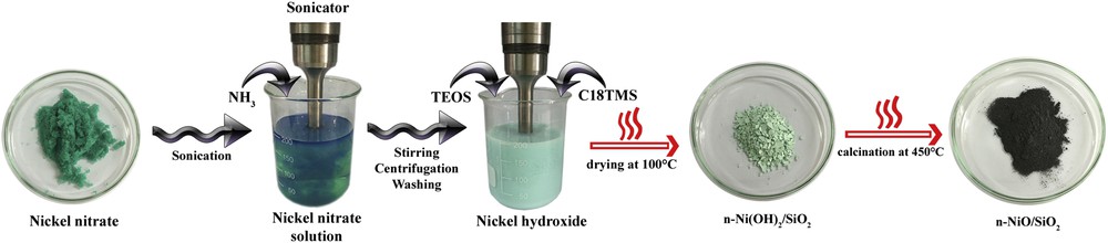
Schematic of the fabrication of the n-NiO/SiO2 catalyst.
2.3 Nanocatalyst characterization techniques
A PANalytical diffractometer at room temperature with Cu Kα radiation (45 kV, 40 mA) was used to record XRD patterns of the fresh and used nanocatalysts. Diffractograms were collected in the 2θ range of 5°–80°. The crystal phase and structure of n-NiO/SiO2 catalysts were determined. X'pert HighScore software was used for diffractogram evaluation. Average crystallite size was obtained by using the global Scherrer equation as follows:
| (3) |
TEM images of the virgin nanocatalyst and produced nanocarbon were captured by using FEI Tecnai, controlled at an accelerating voltage of 200 keV. FESEM images of as-produced nanocarbon and the elemental composition of the nanocatalysts were acquired using FEG Quanta 450 operated at 10 kV and EDX-Oxford, respectively.
H2-TPR measurements were performed using a Micromeritics TPR 2720 analyzer. A total of 0.03 g of a catalyst sample was placed in a U-tube sample holder, and the sample was first cleaned at 130 °C for 60 min by flushing with helium gas. Upon degassing, the reductive gas mixture, which consists of 5% hydrogen and balance nitrogen, was streamed through the sample at a flow rate of 20 mL/min. The sample was heated from 150 to 650 °C to obtain the TPR profiles of the sample.
2.4 Catalytic performance
2.4.1 Experimental setup
A fixed catalyst bed reactor constructed with stainless steel (SS310S) was used for catalytic activity evaluation. The schematic representation of the methane decomposition reactor is shown in Scheme 2. The reactor was constructed with the following dimensions: outer diameter = 6.03 cm, wall thickness = 0.87 cm, and height = 120 cm. A quartz tube (3.56 cm internal diameter, 4 cm outer diameter, and 120 cm height), obtained from Technical Glass Products (Painesville, USA), was placed inside the reactor to prevent interaction of the feed gas with stainless steel. A quartz frit with 150–200 μm porosity was used as the catalyst bed. Heat was supplied with a vertically mounted, three-zone tube furnace (model TVS 12/600, Carbolite, UK). Temperature measurements were recorded by using two K-type thermocouples (1/16 in. diameter, Omega, USA). The first thermocouple was installed on the exterior surface of the stainless steel tube. The second thermocouple was inserted into the quartz tube momentarily for calibration and removed afterward from the quartz tube before testing, as the internal copper material could affect the TCD [55]. In addition, pressure and temperature indicators were placed at different locations to control the operating conditions. A two-differential pressure transducer (0″ H2O to 4″ H2O) was supplied by Sensocon to measure the pressure drop across the reactor. Mass flow controllers (Dwyer, USA) in the range of 0–2 L/min were used to control the gas flow rates. The outflow gas was then cooled down to room temperature by an air cooler. Solid particles with sizes exceeding 2 nm and components with higher molecular weight were filtered using two filters (38 M membrane, Avenger, USA). A 0.25 in. inline filter packed with a 2 μm ceramic filter was used for additional protection of the analyzer against the fine particles elutriated with the effluent gas. The volume percentages (vol %) of methane and hydrogen in the out stream gas after methane decomposition were measured using a Rosemount Analytical X-STREAM on-line multicomponent gas analyzer. The gas analyzer was calibrated using certified gases of nitrogen, methane, and hydrogen, and the accuracy of these measurements was further confirmed with blended gas mixtures. The lowermost measuring range detected by the gas analyzer for methane and hydrogen is 0–1000 ppm and 0%–2%, respectively, whereas the uppermost measuring value is 100% for both gases.
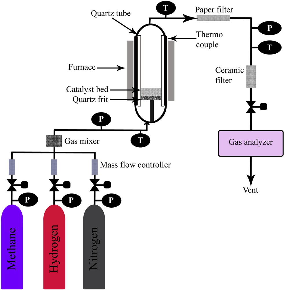
Simplified schematic visualization of the methane decomposition unit.
2.4.2 Preliminary catalytic activity evaluation
Temperature-programmed methane decomposition (TPMD) was conducted as a preliminary catalytic examination. 0.5 g of the catalyst was evenly spread over the catalyst bed. The interior of the reactor and the nanocatalyst were cleaned from air and vapors by passing nitrogen with a flow rate of 1 L/min for 30 min at room temperature. Catalyst bed temperature was increased to 550 °C with a ramp of 20 °C/min and 30% H2 in N2 feed was passed for 2.5 h to reduce the metal oxide catalyst to its metallic form. The furnace temperature was, then, decreased to 300 °C by an air cooler under nitrogen flow. After that nitrogen flow was replaced with methane (99.995%) with a flow rate of 0.6 L/min for temperature-programmed decomposition from 300 to 900 °C with heating ramp of 5 °C/min.
2.4.3 Isothermal methane decomposition
The catalyst bed was uniformly covered with 0.5 g of catalyst to conduct TCD. After 2.5 h of the reduction process as described in preliminary activity evaluation, the temperature of the catalyst bed was increased to 625 °C under nitrogen flow. Once the desired temperature was reached, nitrogen flow was replaced with 99.995% methane with a flow rate of 0.6 L/min for evaluating methane conversion. The carbon yield of catalysts was evaluated based on the extent of methane conversion against time on the stream for 180 min run time using Eq. 4:
| (4) |
3 Results and discussion
3.1 Synthesis and characterization of n-NiO/SiO2 catalysts
The preliminary concern in the field of nanocatalysis is the development of catalysts with lower size, desired shapes, and porosity. The catalytic characteristics of nanosized materials are firmly related to their morphology, size distribution, and electronic properties. Furthermore, preparation methods, stabilizer, and supports selected to synthesize the nanomaterial can also influence its characteristic properties [56]. Hence, numerous research efforts have been devoted to explore the variance of catalytic characteristics with synthesis parameters. The development of the nanomaterial from their precursors by the bottom-up method is a compelling practice in nanotechnology. We have implemented the coprecipitation cum modified Stöber method [17] for preparing the n-NiO/SiO2 catalyst and studied the influence of metal/silicate ratio, TEOS/C18TMS ratio, and various solvents on the physical, chemical, and catalytic characteristic of n-NiO/SiO2. Stöber method was incorporated with coprecipitation in the sense of enhancing characteristics of coprecipitated n-NiO. In the modified Stöber method, the coprecipitated n-NiO particles were supported with silicate by treatment with a mixture of C18TMS and TEOS in alcoholic media [54]. Hence, the chances of n-NiO particle agglomeration and formation of free metal oxides and silicates via the establishment of hydrolysis in the presence of water was efficiently minimized [57,58]. C18TMS porogen was added to the sample preparation mixture to enhance the porous characteristics by producing more pores inside the silica network of the catalyst through silica polymerization. Further porosity augmentation was achieved by heat treatment such as calcination under air at 450 °C and reduction with 30% H2 stream balanced with N2 at 550 °C, which remove all organic moieties and convert metal oxides to metal. In this research, we controlled the porosity of n-NiO/SiO2 catalysts by changing the quantity of C18TMS porogen. Different amounts of C18TMS with respect to the silica precursor TEOS concentration have altered the porosity and influenced the overall catalytic performance. A series of characterization were conducted to examine the characteristics of n-NiO/SiO2 catalysts as follows.
3.2 XRD
Fig. 1 exhibits the XRD patterns of all freshly prepared n-NiO/SiO2 catalysts before reduction treatment. The extension of catalytic structural order and apparent size of crystallites are extensively revealed by XRD analysis. However, the endurance of catalyst and catalytic activity are dependent on these characteristics. Fig. 1 demonstrates the variances of intensity, broadness, and the position of diffraction patterns according to the variation in precursor quantity and ratios. Miller indices (hkl) of three major diffraction peaks of n-NiO/SiO2 catalysts are (111), (200), and (220), respectively, which correspond to the reflections of NiO solid phases. However, the pattern for SiO2 is absent because of its X-ray amorphous characteristics. Table 2 presents detailed XRD results. The average crystallite size of n-NiO/SiO2 catalysts calculated using the global Scherrer equation (furnished in Table 2) was evidently close to the mean particle size obtained from BET analysis (furnished in Table S1). The results indicate that the silicate support evidently prevents NiO particle agglomeration [44]. The calcined n-NiO/SiO2 catalysts exhibited the cubic NiO phase with typical reflections at 2θ = 37°, 43°, and 62°, respectively. The intensity, width at half-maximum, and 2θ values slightly varied with different precursor ratios. The positions of diffraction peaks are in good agreement with those given in JCPDS No. 01-073-1523 for the NiO phase. Among the prepared catalysts, n-NiO/SiO2_(6) prepared with 1.2 mL of TEOS exhibits NiO diffraction peaks with moderately lower intensity, which proves its lower structural ordering. Likewise, n-NiO/SiO2_(6) demonstrated poor catalytic stability at 625 °C (Fig. 5). However, all other catalysts prepared with 1.2 mL of C18TMS and mixture of TEOS and C18TMS showed better crystal orders and catalytic performances. Henceforth, porous silicate produced with C18TMS porogen interacts with NiO phases more effectively and executes better catalytic conditions and results in improved thermocatalytic methane decomposition. However, the examined solvents did not significantly influence the crystallinity of synthesized materials. Catalysts prepared using methanol, ethanol, 2-propanol, and n-butanol exhibited virtually similar peak intensities and Scherrer crystal sizes as shown in Fig. 1 and Table 2.

XRD patterns of each n-NiO/SiO2 catalyst before reduction treatment with hydrogen. Planes of corresponding peaks are indicated.
The 2θ angle of major diffraction peaks in degrees, and crystalline size corresponds to each peak according to the Scherrer equation and their average value in nanometers, interplanar distances in Å, and crystal structure of catalysts with different precursor concentration before TCD process from XRD analysis.
| Nanocatalyst | 2θ (°) | Ni (111) (nm) | Ni (200) (nm) | Ni (220) (nm) | Average crystal size (nm) | Interplanar distances, d (Å) | Structure formed |
| n-NiO/SiO2_(1) | 37.25, 43.27, 62.81 | 31.13 | 26.85 | 23.77 | 27.25 | 2.41373, 2.09085, 1.47935 | Cubic |
| n-NiO/SiO2_(2) | 37.21, 43.26, 62.85 | 31.13 | 31.74 | 31.69 | 31.52 | 2.41585, 2.09105, 1.47847 | Cubic |
| n-NiO/SiO2_(3) | 37.22, 43.27, 62.84 | 34.25 | 31.44 | 31.18 | 32.29 | 2.41520, 2.09077, 1.47751 | Cubic |
| n-NiO/SiO2_(4) | 37.22, 43.26, 62.81 | 31.13 | 31.74 | 34.57 | 32.48 | 2.41546, 2.09133, 1.47944 | Cubic |
| n-NiO/SiO2_(5) | 37.22, 43.26, 62.86 | 31.13 | 34.74 | 34.58 | 33.48 | 2.41553, 2.09124, 1.47842 | Cubic |
| n-NiO/SiO2_(6) | 37.21, 43.23, 62.69 | 38.04 | 31.80 | 13.57 | 27.80 | 2.41625, 2.09090, 1.48191 | Cubic |
| n-NiO/SiO2_(7) | 37.22, 43.26, 62.84 | 26.34 | 24.93 | 23.77 | 25.01 | 2.41532, 2.09121, 1.47876 | Cubic |
| n-NiO/SiO2_(8) | 37.23, 43.27, 62.83 | 34.25 | 31.74 | 38.03 | 34.67 | 2.41473, 2.09072, 1.47902 | Cubic |
| n-NiO/SiO2_(9) | 37.30, 43.33, 62.91 | 24.46 | 23.28 | 25.36 | 24.37 | 2.41079, 2.08805, 1.47726 | Cubic |
| n-NiO/SiO2_(10) | 37.24, 43.27, 62.82 | 29.54 | 30.09 | 35.57 | 31.73 | 2.41392, 2.09080, 1.47926 | Cubic |
| n-NiO/SiO2_(11) | 37.24, 43.31, 62.89 | 29.54 | 25.94 | 39.04 | 31.51 | 2.41391, 2.08915, 1.47778 | Cubic |
| n-NiO/SiO2_(12) | 37.22, 43.27, 62.79 | 32.13 | 32.74 | 28.15 | 31.01 | 2.41534, 2.09084, 1.47980 | Cubic |
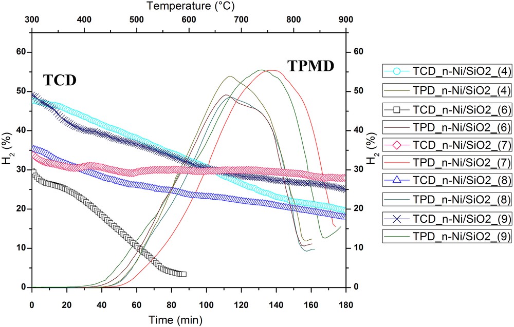
Influence of the C18TMS/TEOS ratio on the hydrogen formation percentage during TPMD and TCD at 625 °C. Flow rate = 0.6 L/min; catalyst weight = 0.5 g. The bottom X-axis is time (min) and left Y-axis is H2 (vol %) for TCD. Top X-axis is temperature (°C) and right Y-axis is H2 (vol %) for TPMD.
3.3 H2-TPR
The reducibility and metal–support interaction were studied using quantitative TPR analysis. The influence of nickel/silicate ratio, C18TMS/TEOS ratio, and different solvents on the reduction characteristics of produced n-NiO/SiO2 catalysts are exhibited in Fig. 2(a–c), respectively. The detailed peak description and the volume of hydrogen consumed by each catalyst are exhibited in Table 3. The H2-TPR profile of n-NiO/SiO2 catalysts prepared with various concentrations of precursors and solvents exhibit only one peak between 250 and 650 °C. The peak could be assigned to the complete reduction of Ni2+ species to Ni0 metallic form, thus supporting previous records [59,60]. The single peak observed with H2-TPR profiles indicates a homogenous interaction between the metal and support. However, a shoulder-type separation from the main peak forming single small features can be seen in TPR profiles. The shoulder could be because of the restrained hydrogen diffusion to the inside of the grain and oxygen migration from the bulk to the surface, because of a metal cover formed with silicate [61]. Furthermore, the reduction in surface oxygen also leads to the formation of shoulders on the main Ni2+ → Ni0 reduction peak. Hence, high surface area was observed with NiO sample, which could bind more oxygen to the surface.
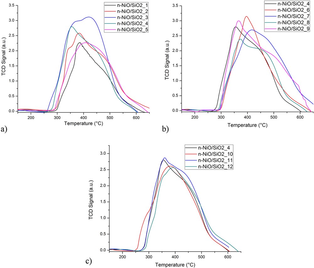
Effect of different precursor conditions on H2-TPR profile (a) nickel/silicate ratio, (b) C18TMS/TEOS ratio, and (c) solvent.
Hydrogen conception and TPR profile details of each catalyst.
| Nanocatalyst | Temperature at maximum (°C) | Volume (mL/g STPa) | Peak height (au) |
| n-NiO/SiO2_(1) | 382.6 | 227.327 | 2.284 |
| n-NiO/SiO2_(2) | 377.0 | 250.402 | 2.238 |
| n-NiO/SiO2_(3) | 420.3 | 291.349 | 3.230 |
| n-NiO/SiO2_(4) | 355.6 | 261.602 | 2.859 |
| n-NiO/SiO2_(5) | 407.1 | 226.857 | 2.267 |
| n-NiO/SiO2_(6) | 396.2 | 243.281 | 3.172 |
| n-NiO/SiO2_(7) | 383.3 | 282.038 | 2.563 |
| n-NiO/SiO2_(8) | 366.6 | 254.871 | 2.999 |
| n-NiO/SiO2_(9) | 373.6 | 271.173 | 2.419 |
| n-NiO/SiO2_(10) | 379.9 | 254.357 | 2.633 |
| n-NiO/SiO2_(11) | 360.4 | 261.492 | 2.915 |
| n-NiO/SiO2_(12) | 391.6 | 255.658 | 2.573 |
a Standard Temperature and Pressure.
The hydrogen consumption quantified from H2-TPR profile using ChemiSoft TPx V1.02 software indicates that the peak volume increased with the increase in precursor concentration in a synthesis mixture as shown in Fig. 2a. Although both n-NiO/SiO2_(1) and n-NiO/SiO2_(2) samples exhibited very similar peak maxima, the hydrogen consumption of the former (250.402 mL/gcat) was much higher than that of the latter (227.327 mL/gcat). The difficulty of the reduction of metallic structure in the latter sample was attributed to the stronger metal–support interaction. Furthermore, hydrogen consumption volume increased with the increase in the quantity of C18TMS in the preparation mixture. n-NiO/SiO2_(3) and n-NiO/SiO2_(7) prepared with 1.2 mL of C18TMS recorded the highest hydrogen consumption, which are 291.349 and 282.038 mL/gcat, respectively. The higher hydrogen consumption could be attributed to the difficulty to reduce silicate-supported NiO. Hence, the silicate support acquired denser and higher microporous characteristics from C18TMS [62], which limit the penetration of reducing gas to metal core, supporting BET results in Table S1. The results evidently elucidated the dependency of metal–support interaction on the C18TMS/TEOS ratio. However, solvents such as methanol, ethanol, 2-propanol, and n-butanol exhibit negligible effects on the reduction characteristics. In general, n-NiO/SiO2 prepared by coprecipitation cum modified Stöber method exhibits a broader H2-TPR peak than those prepared by the conventional preparation method, indicating stronger metal–support interaction occurring in the modified Stöber method [59,63]. Hence, a denser silicate support was formed over n-NiO and resulted in the difficulty of hydrogen diffusion and hence n-NiO reduction. Moreover, the extension of the reduction profile of n-NiO/SiO2_(7) to a higher temperature zone as compared with the other catalysts may be accredited to the larger NiO particles, as reported in the BET results (Table S1).
3.4 TEM and EDX
TEM images and the comparison chart of average particle sizes are exhibited in Figs. 3 and 4, respectively. The average particle size from TEM clearly supports XRD (Table 2), BET (Table S1), and H2-TPR results (Table 3). n-NiO/SiO2 particles exhibit virtually uniform distribution in the TEM scanned area with a minor standard deviation as shown in Fig. 4. However, the particles showed different shapes. Furthermore, the TEM images have visualized that the silicate surfaces in the experimented catalysts become rougher as the molar ratio of C18TMS in the synthesis mixture increases. This is because of the sparse and irregular polymerization in the silica networks as perceived in XRD and BET results [64]. Moreover, the magnetic properties of n-NiO resulted in particle agglomeration in certain area [58].
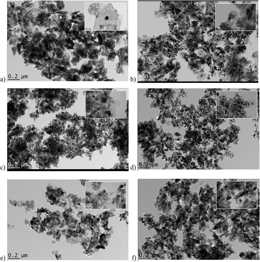
TEM images of (a) n-NiO/SiO2_(6), (b) n-NiO/SiO2_(4), (c) n-NiO/SiO2_(7), (d) n-NiO/SiO2_(10), (e) n-NiO/SiO2_(11), and (f) n-NiO/SiO2_(12). Higher resolution images are given as inset images.
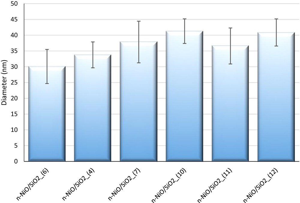
Comparison of the average particle size calculated from TEM images; 75 nanoparticles were considered to measure the average particle size. ImageJ software was used to measure the particle size.
Elemental compositions were confirmed by EDX analysis. The weight and atomic percentages of each element are summarized in Table 4, and the elemental mappings are shown in Fig. S3. As expected, peaks for Ni, O, and Si elements were observed in the mapped area. The elemental compositions vary (Table 4) according to the variation in precursor materials used in synthesis. The quantity of Si increases with increasing quantity of C18TMS and TEOS in the preparation mixture. However, Ni decreases with the increase of C18TMS and TEOS. No other elements were detected in these samples except for traces of carbon (C). The observed C peak could be attributed to the element present in the carbon tape used for EDX analysis and that composition of which was omitted from the elemental percentage composition table.
Elemental composition of prepared catalysts from EDX reports. EDX mapping is exhibited in Fig. S3 in Supporting Information.
| Nanocatalyst | Oxygen | Silicon | Nickel | ||||||
| Line type | Weight % | Atomic % | Line type | Weight % | Atomic % | Line type | Weight % | Atomic % | |
| n-NiO/SiO2_(1) | (K) | 20.95 | 47.67 | (K) | 3.92 | 4.38 | (K) | 75.13 | 47.95 |
| n-NiO/SiO2_(2) | (K) | 21.26 | 48.62 | (K) | 3.38 | 4.40 | (K) | 75.36 | 46.98 |
| n-NiO/SiO2_(3) | (K) | 20.86 | 47.76 | (K) | 4.19 | 5.47 | (K) | 74.95 | 46.77 |
| n-NiO/SiO2_(4) | (K) | 18.61 | 44.48 | (K) | 3.52 | 4.80 | (K) | 77.87 | 50.72 |
| n-NiO/SiO2_(5) | (K) | 17.87 | 43.80 | (K) | 1.88 | 2.62 | (K) | 80.25 | 53.58 |
| n-NiO/SiO2_(6) | (K) | 21.20 | 48.07 | (K) | 4.78 | 6.18 | (K) | 74.02 | 45.75 |
| n-NiO/SiO2_(7) | (K) | 19.72 | 46.67 | (K) | 2.22 | 3.00 | (K) | 78.06 | 50.34 |
| n-NiO/SiO2_(8) | (K) | 20.11 | 46.50 | (K) | 4.63 | 6.09 | (K) | 75.26 | 47.41 |
| n-NiO/SiO2_(9) | (K) | 21.25 | 48.58 | (K) | 3.49 | 4.54 | (K) | 75.26 | 46.88 |
| n-NiO/SiO2_(10) | (K) | 19.27 | 45.31 | (K) | 4.24 | 5.68 | (K) | 76.48 | 49.00 |
| n-NiO/SiO2_(11) | (K) | 22.01 | 49.65 | (K) | 3.56 | 4.58 | (K) | 74.43 | 45.76 |
| n-NiO/SiO2_(12) | (K) | 22.07 | 49.75 | (K) | 3.55 | 4.55 | (K) | 74.38 | 45.69 |
3.5 Thermocatalytic methane decomposition
TPMD was conducted over 0.5 g of the catalyst with 99.995% methane to evaluate the catalytically active temperature zone for each catalyst. Influence of the C18TMS/TEOS ratio and different solvents on the catalytically active temperature zone of n-NiO/SiO2 catalysts is exhibited in Fig. 5 and S4(b). TPMD results for nickel/silicate ratios overlap each other and hence were excluded from Fig. S4(a) for clarity. TPMD results evidently demonstrate that the silicate-supported nickel nanocatalysts prepared by coprecipitation cum modified Stöber method are truly active from ∼450 to ∼720 °C [65]. The active zone of n-NiO/SiO2 catalysts was extended to a higher temperature with increasing quantity of C18TMS in the preparation mixture as shown in Fig. 5. However, solvents such as methanol, ethanol, 2-propanol, and n-butanol do not considerably effect catalytically active temperature zone [Fig. S4(b)].
Isothermal catalytic methane decomposition was conducted at 625 °C with a flow rate of 0.6 L/min in the fixed catalyst bed reactor to estimate methane decomposition activity sustainability of each catalyst. According to our previous research works, n-NiO/SiO2 catalyst prepared by coprecipitation cum modified Stöber method was rapidly deactivated above 675 °C because of its high temperature sensitivity [17]. Previous research results also revealed that Ni-based catalysts do not effectively decompose methane beyond 700 °C [66]. Similarly, methane conversion was comparatively lower below 575 °C [66]. Hence, we have selected 625 °C for the evaluation of the influence of catalyst preparation parameters on the catalytic activity and stability. The isothermal methane conversion percentage and the activity range undeniably followed the temperature range observed in TPMD [Fig. 5 and S4(b)].
The Rosemount Analytical X-STREAM on-line gas analyzer detected only hydrogen and methane according to the methane decomposition equation (CH4 → 2H2 + C). n-NiO/SiO2_(1), n-NiO/SiO2_(2), and n-NiO/SiO2_(3) prepared with 0.02, 0.04, and 0.06 mol of nickel precursors maintained fairly similar metal/silicate ratio (Table 4), respectively. Accordingly, n-NiO/SiO2_(1), n-NiO/SiO2_(2), and n-NiO/SiO2_(3) maintained similar catalytic performance, regardless of increasing precursor concentration in catalyst preparation. Correspondingly, catalyst (1), (2), and (3) showed activity loss of 73%, 78%, and 71% after 180 min of methane on stream analysis, respectively, as shown in Fig. 6. The activity loss is calculated using Eq. 5:
| (5) |
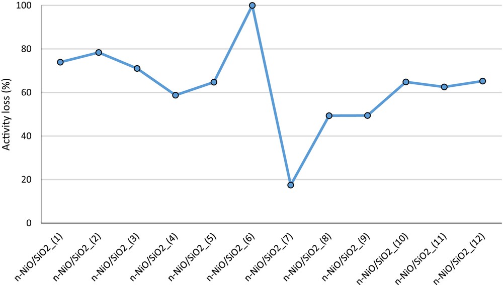
Activity loss of each n-NiO/SiO2 catalyst in percentage after 180 min of activity examination. The corresponding methane evolution curves are shown in Fig. S5.
Comparatively lower activity loss observed with n-NiO/SiO2_(3) may be attributed to the higher Ni and SiO2–support interaction, as indicated in the H2-TPR pattern shift in Fig. 2(a). Furthermore, increase in silicone content (Table 4) also helps to prevent the agglomeration of the n-NiO/SiO2_(3) catalyst to sustain the activity. These results clearly demonstrate that the catalytic action of n-NiO/SiO2 prepared by coprecipitation cum modified Stöber method do not vary much with the increase in the precursor quantity to produce nanocatalysts in the gram amount. Furthermore, the nanocarbon yields produced over n-NiO/SiO2_(1), n-NiO/SiO2_(2), and n-NiO/SiO2_(3) are 3108%, 2936%, and 3061%, respectively, as shown in Fig. 7. However, n-NiO/SiO2_(4) prepared with a mixture of 0.6 mL of C18TMS and 0.6 mL of TEOS exhibited stable performance with a higher nanocarbon yield as compared with those of nanocatalysts (1), (2), and (3). This may be attributed to the more efficient access of methane molecules toward the active nickel metal because of thinner but efficient silicate support. Hence, the porosity and denseness molded with 0.6 mL of C18TMS and TEOS are efficient to extend the stability to a longer experimental duration. However, further decrease in silicate concentration in n-NiO/SiO2_(5), as shown in Table 4, results in faster activity loss, which was prepared with a mixture of 0.3 mL of C18TMS and 0.3 mL of TEOS. Furthermore, the lowest metal–support interaction of n-NiO/SiO2_(5) is evidently proven by the lowest hydrogen consumption of 226.85 mL/g in H2-TPR profile [Fig. 2(a) and Table 3].
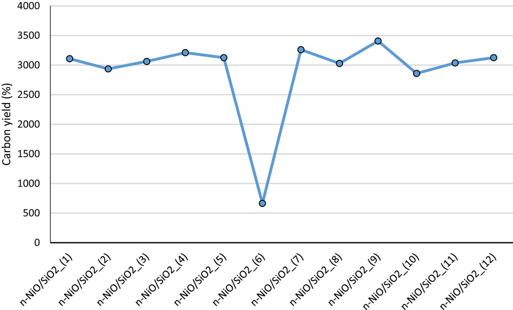
Nanocarbon yield calculated over each n-NiO/SiO2 catalyst after 180 min of activity examination.
Different C18TMS/TEOS ratios in the catalyst preparation solution definitely influence catalytic properties, as shown in Fig. 5. One can observe that the n-NiO/SiO2_(7) catalyst prepared with 0 mL of TEOS and 1.2 mL of C18TMS has the lowest activity loss of 17.46% (Figs. 5 and 6). Conversely, n-NiO/SiO2_(6) catalyst prepared with 1.2 mL of TEOS and 0 mL of C18TMS exhibited the poorest catalytic performance and completely deactivated within the experimental duration. However, the initial hydrogen productions of both n-NiO/SiO2_(6) and n-NiO/SiO2_(7) are comparable. Furthermore, the n-NiO/SiO2 catalysts prepared with the mixture of C18TMS and TEOS exhibit higher initial conversion and comparatively lower activity loss with time. The comparable initial methane conversion in both n-NiO/SiO2_(6) and n-NiO/SiO2_(7) may be because of the analogous quantity of active accessible nickel phase, which is supported by the simultaneous reduction peak initiation at 296 °C for both catalysts in H2-TPR profile [Fig. 2b]. However, the stabilities were varied depending on their sustainability to tolerate the temperature while producing nanocarbon filaments. The higher stability of n-NiO/SiO2 catalysts prepared with various quantities of C18TMS may be attributed to the higher amount of microporous area, as indicated in BET results (Table 2). A 1.2 mL portion of TEOS and 0 mL of C18TMS produced lesser micropores in n-NiO/SiO2_(6), which resulted in complete deactivation. The addition of C18TMS into the catalyst preparation mixture enhanced the microporosity from 10.7% to 26.8%, which resembles the hierarchical porous catalyst [67]. Hence, the synergistic effect between mesopores and higher quantity of micropores results in higher catalytic activity and stability in TCD. Furthermore, the catalyst with higher microporosity results in the formation of nanocarbon by the tip-growth carbon formation mechanism [68] with the active metal on the tip of carbon, hence conserving catalytic activity with time extension, as shown in FESEM images of produced nanocarbon (Fig. 8). These results reveal the significant influence of pore size distribution on the initial activity and catalytic activity maintenance during TCD. Regardless of the influence of the C18TMS/TEOS ratio on methane conversion behavior, analyzed solvents such as methanol, ethanol, 2-propanol, and n-butanol do not exhibit a significant variation in the catalytic performance with virtually similar activity loss of 62 ± 4%, as shown in Fig. S4(b) and S6. The higher and conformational stability observed with n-NiO/SiO2 catalysts may be attributed to the microcapsular structure with high porosity, providing a sufficient area for methane molecules to collide and decompose to hydrogen and nanocarbon [69–71]. Furthermore, highly stable silicate support evidently prevents the agglomeration of active Ni-phase and maintains the catalyst particle size for carbon nanofilament growth [43] and hence resulted in a superior performance. According to the results discussed here, it is evident that the activity is not only dependent on a specific characteristic of the catalyst but the overall characteristics such as porosity, surface area, particle size, availability of active phase, active phase support, denseness of support, metal–support interaction, and so forth. The finest catalyst characteristics and the corresponding preparation condition are yet being optimized.

FESEM images of produced nanocarbon over (a) n-NiO/SiO2_(7), (b) n-NiO/SiO2_(4), and (c) n-NiO/SiO2_(6) catalysts.
FESEM images of the produced nanocarbon over n-NiO/SiO2_(7), n-NiO/SiO2_(4), and n-NiO/SiO2_(6) catalysts are exhibited in Fig. 8(a–c), respectively. The presence of nickel particle at the tip of nanocarbons can be identified as bright spots, which confirms the tip-growth mechanism of nanocarbon formation. On the basis of the previous reports, the average diameter of nanocarbon produced over catalysts is comparable to the Ni crystallite size calculated from XRD patterns after TCD examination [72–74]. XRD patterns of nanocatalysts after TCD are exhibited in Fig. 9. The diffraction peaks at 2θ = 26.2280° and 42.7556° are characteristic to graphite with reference to JCPDS No. 98-005-3780. The peaks at 2θ = 44.4252°, 51.7634°, and 76.2959° correspond to Ni-phases, showing good agreement with JCPDS No. 03-065-0380. The crystallite sizes of n-NiO/SiO2_(7), n-NiO/SiO2_(4), and n-NiO/SiO2_(6) calculated from XRD patterns were 22.86, 26.1, and 33.63 nm, respectively. Similarly, the average diameters of nanocarbons measured with ImageJ software were 24.74 ± 3.1, 27.94 ± 2.8, and 36.84 ± 4.1 nm, respectively. Furthermore, we can observe that the average diameter of nanocarbon decreases with the increase in the quantity of C18TMS in the catalyst preparation mixture. These FESEM (Fig. 8) and XRD (Fig. 9) results clearly revealed the dependence of stability of the nano-nickel catalyst on the C18TMS/TEOS ratio. In addition, the bright metal particles can be seen to be highly agglomerated at the tip of nanocarbon produced over the n-NiO/SiO2_(6) catalyst [Fig. 8(c)]. This active phase agglomeration results in its faster deactivation. The produced smooth nanocarbons of several micrometer lengths are closely woven together, hence their actual length cannot be measured.

XRD patterns of n-NiO/SiO2_(7), n-NiO/SiO2_(4), and n-NiO/SiO2_(6) catalysts after 180 min of TCD.
4 Conclusion
This study involved the usage of Ni(NO3)2·6H2O as a raw material to produce nanosized nickel oxide powder with crystal size of ∼30 nm by coprecipitation cum modified Stöber method. Particle size, porosity, and catalytic activity management were efficiently controlled by systematic variance in the ratio of C18TMS porogen to the TEOS silica precursor. Microporous characteristics were increased from 10.7% to 26.8% by increasing the quantity of C18TMS as compared with TEOS in the preparation mixture. In addition, the absence of C18TMS in the preparation mixture resulted in lower crystal structure order and consequently lowers catalytic stability. n-NiO/SiO2 catalysts prepared with 0.02, 0.04, and 0.06 mol of nickel precursors established similar catalytic performance elucidating the advantage of the coprecipitation cum modified Stöber method for nanocatalyst preparation in gram quantity. Furthermore, maximum catalytic stability for methane decomposition was observed when the catalyst was prepared with 1.2 mL of C18TMS and 0 mL of TEOS. This higher stability is attributed to the superior synergistic effect between higher quantity of micropores and mesopores. However, the catalyst prepared with 0 mL of C18TMS and 1.2 mL of TEOS exhibited lowest catalytic stability and was completely deactivated during the experimental duration of 180 min. However, the investigated solvents, including methanol, ethanol, 2-propanol, and n-butanol do not exert any significant effects on the physicochemical properties of catalysts.
Acknowledgments
The authors gratefully acknowledge the financial support from GSP-MOHE (MO008-2015), University of Malaya, Malaysia.