

1 Introduction
Fracture populations formed in a single tectonic environment where the host rocks have similar mechanical properties commonly show a roughly linear relationship between trace length and maximum displacement (Fig. 1). However, the scatter is normally large. Not only do the linear relationships vary between fracture populations, but they also vary within a population and, moreover, on individual faults. Thus, although roughly linear relations commonly exist for individual faults over short periods of time, over longer periods of time the correlation between rupture length and displacement has a large scatter, commonly by an order of a magnitude or more [3,28]. These observations suggest that some properties of the rock determining the fault displacement may be highly variable.
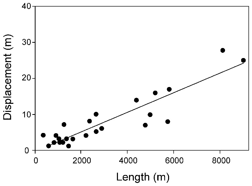
Vertical displacement (throw) versus trace length of 26 normal faults dissecting thick (basaltic) pahoehoe lava flows of the Holocene rift zone in Iceland. Although all the faults dissect lava flows of very similar stiffnesses, there is a large scatter in the data. Part of the scatter may be attributable to the differences in the stiffnesses of the cores and damage zones of these faults; part to different controlling dimensions [13].
Déplacement vertical (rejet) en fonction de la longueur de trace de 26 failles normales disséquant des coulées de lave pahoehoe (basaltique) de la zone de rift holocène d'Islande. Même si toutes les failles dissèquent des coulées de lave de rigidités très similaires, il y a une grande dispersion des données. Une partie de cette dispersion est attribuable aux différences de rigidité entre cœurs et zones de dégât de ces failles et une autre à l'utilisation de différentes cotes de contrôle [13].
Field observations show that fault zones normally consist of two main structural units, namely a fault core and a fault damage zone (Fig. 2). In major fault zones, the core is from several metres to tens of metres thick and contains many small faults and fractures. Its most distinctive rocks, however, are breccias and other cataclastic rocks. The fault damage zone, which in major fault zones may be as thick as several kilometres, consists primarily of numerous fractures and faults that gradually increase in number towards the core. As the core and the damage zone change with time, so do their mechanical properties, in particular their Young's moduli (Fig. 2).
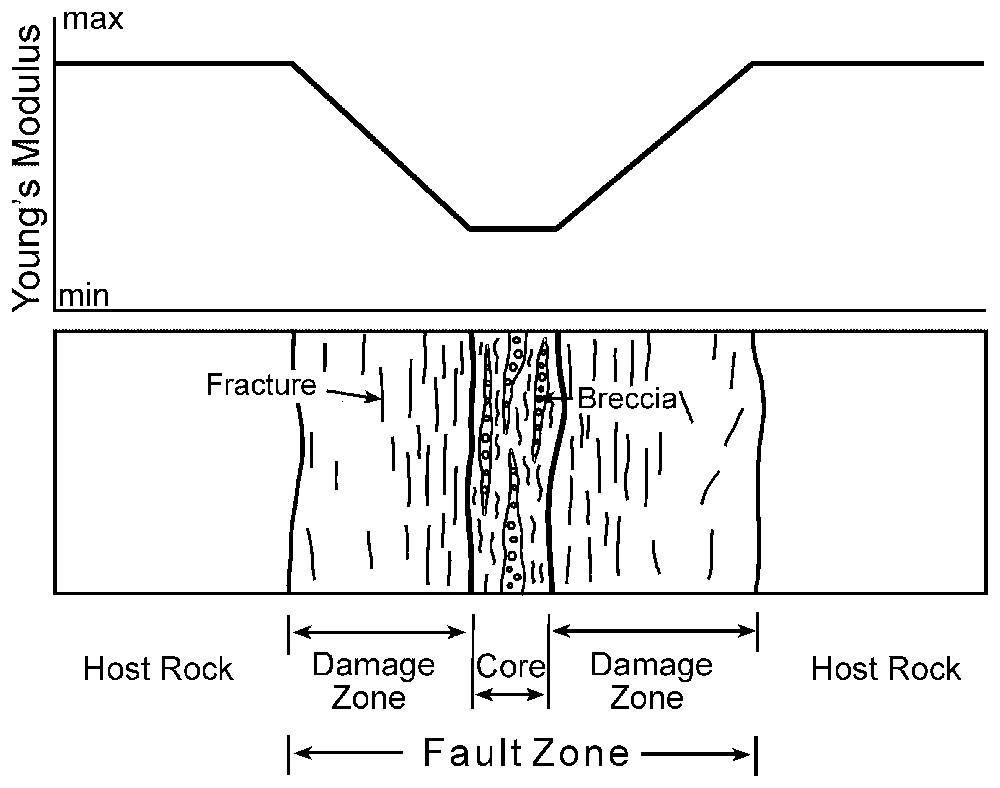
Major fault zone is composed of two main mechanical units: a fault core and a fault damage zone. Fracture frequency commonly increases gradually towards the core, thereby decreasing the effective stiffness towards the central parts of the fault zone. As the fault zone develops, these units gradually become thicker and largely control the displacement on the fault, which is primarily along the core or its contact with the damage zone.
Zone majeure de faille composée de deux unités mécaniques principales : le cœur de la faille, la zone de dégât. La fréquence de fracture augmente en général graduellement jusqu'au cœur, diminuant ainsi la rigidité effective vers les parties centrales de la zone de faille. Quand la zone de faille se développe, ces unités s'épaississent graduellement et contrôlent largement le déplacement le long de la faille, qui est d'abord le long du cœur ou au contact de la zone de dégât.
The principal aim of this paper is to show how the development of the fault core and damage zone may affect the mechanical properties, in particular Young's modulus, of the rock where the fault displacement takes place. This is done by considering, first, the analytical equations relating displacement and Young's modulus of the rock, and, second, the likely effects of the evolution of the fault damage zone and core on the associated Young's modulus. A second aim of the paper is to use the results derived in the theoretical section to explain the large temporal and spatial variation in length/displacement ratios of faults.
2 Fault displacement and Young's modulus
Depending on the relative displacement across the fracture plane, all tectonic fractures in the crust may be classified mechanically as extension fractures and shear fractures. The sense of displacement is perpendicular to, and away from, the plane of an extension fracture, but parallel to that of a shear fracture. When tectonic fractures are modelled as ideal cracks in elastic bodies, use is made of the three basic types of displacements of the crack surfaces: mode I, mode II and mode III [13,22,25].
Mode I, where the crack surfaces move directly apart, is referred to as opening or tensile mode and is used to model extension fractures such as many dykes, mineral veins and joints. Mode II, where the crack surfaces slide over one another in a direction perpendicular to the leading edge (tip) of the crack, is referred to as sliding or in-plane shear mode and is used to model many dip-slip faults. Mode III, where the crack surfaces move relative to one another in a direction that is parallel to the leading edge of the crack, is referred to as tearing or anti-plane shear mode and used to model many strike-slip faults as well as dip-slip faults that go (as through cracks) from one free surface of the elastic body to another [13,22,25].
When the strike dimension L of a dip-slip fault is its controlling dimension, a mode III crack model is appropriate [13]. This model applies, for example, to those large normal faults in Iceland that extend from the free surface of the rift zone to the top of an underlying magma reservoir [12,13]. In this model, the ratio of the strike dimension to the fault displacement during a single-event displacement (slip) is:
| (1) |
For a strike-slip fault where the dip dimension R is the controlling one, a mode-III crack model is also appropriate. Then the ratio of the dip dimension to the fault displacement during a slip is [13]:
| (2) |
Eqs. (1) and (2) indicate that the ratio between the controlling dimension of a fault and its displacement during a particular slip is proportional to the Young's modulus, E, of the rock. Alternatively, the displacement for a given controlling dimension is inversely proportional to E; as E gets lower, the displacement increases. The displacement is also directly proportional to the rock Poisson's ratio, ν, and the shear stress Δτ driving the fault displacement. Poisson's ratio does depend on the rock type under consideration, but its range is generally small compared with that of Young's modulus; for most solid crustal rocks Poisson's ratio is between 0.2 and 0.3 [1,16]. For example, soft tuff and basaltic lava flows may have the same Poisson's ratio, 0.25 [1].
One approximate measure of the driving shear stress is the stress drop in earthquakes. For most large interplate earthquakes, the stress drop is around 3 MPa, but for intraplate earthquakes around 10 MPa. The average stress drop in large, shallow earthquakes is around 6 MPa [17]. Thus, the driving shear stress for seismogenic faulting is relatively constant.
It is well known that there is a close interaction between fluids and faulting. Fluids are commonly driven to, and transported along, fault zones [30]. Increasing pore-fluid pressure may help bring a rock mass to shear failure (faulting). Overpressured fluids reduce friction on fault planes and are widely thought to be a necessary condition for most tectonic earthquakes. Fluids are presumably one of the main reasons for the low (1–10 MPa) driving shear stress in seismogenic faulting. Through the driving stress, the mechanical effects of fluids in faulting are thus partly included in Eqs. (1) and (2).
In contrast to the comparatively small variation in Poisson's ratio, Young's modulus, E, can vary widely between rocks and inside fault zones. Because Young's modulus is a measure of ‘stiffness’, and often referred to as such in the engineering literature, it follows that comparatively soft rocks such as many sedimentary and pyroclastic layers and highly fractured rocks have a low Young's modulus, whereas comparatively stiff rocks such as dense and non-fractured igneous and metamorphic rocks have a high Young's modulus [1,16,27].
As regards measurements of Young's modulus, it should be noted, first, that for a given rock the dynamic modulus, particularly at shallow depths in active zones, is much higher than the static modulus [11]. Second, laboratory measurements on small samples, dynamic or static, yield values that are commonly 1.5–5-times greater than those of the field modulus of the same rock [14]; in particular, for igneous and metamorphic rocks the laboratory modulus is commonly 3-times the field modulus. Third, increasing mean stress (and thus increasing depth) increases Young's modulus [14]. Fourth, increasing temperature, increasing porosity, and water content all decrease Young's modulus.
Perhaps the most important effect on the magnitude of the field Young's modulus, particularly at comparatively shallow depths in tectonically active areas, is the fracture frequency in the rock mass [18]. It is well known that Young's modulus of a rock mass is normally less than that of a laboratory sample of the same type of rock. This difference is mainly attributed to fractures and pores in the rock mass that do not occur in small laboratory samples [9,18]. With increasing number of fractures, in particular in a direction perpendicular to the loading, the ratio Eis/Ela shows a rapid decay. Thus, increasing fracturing normally decreases Young's modulus, and so do gouge and breccia in the core and damage zone of an active fault zone (Fig. 2).
3 Damage-zone development
Major fault zones normally consist of two main structural units referred to as the fault core and the fault damage zone (Fig. 2). The core, taking up most of the fault displacement, is also referred to as the fault slip zone [5]. The core contains many faults and fractures, though normally much smaller than those in the fault damage zone, but its characteristic features are breccias, gouge and other cataclastic rocks. The core rock is thus commonly crushed and altered into a soft material that can fail as brittle only during seismogenic faulting. As the core develops, its cavities and fractures become gradually filled with secondary minerals, but during fault slip, the core has a granular-media structure at the millimetre or centimetre scale. Core thicknesses in major fault zones may be from several metres to a few tens of metres.
The damage zone, also referred to as the transition zone [5], consists of sets of fractures that commonly increase in frequency on approaching the fault core [2,4,23], resulting in a general decrease in the effective Young's modulus towards the core (Fig. 2). In an active fault, the fault gouge and breccia of the core itself would also normally have a very low Young's modulus, similar to that of clay, weak sedimentary rocks, or pyroclastic rocks such as tuff [1,15].
As the fault displacement increases so does the thickness of the fault zone (Fig. 3). These results suggest that as the fault grows there will be gradually thicker zones of brecciated and fractured fault rocks around the fault plane. Because the fault rocks are normally soft in comparison with the host rocks, it follows that the stiffness of an active fault zone decreases with time. As a consequence, the L/u ratio in Eqs. (1) and (2) decreases with time.
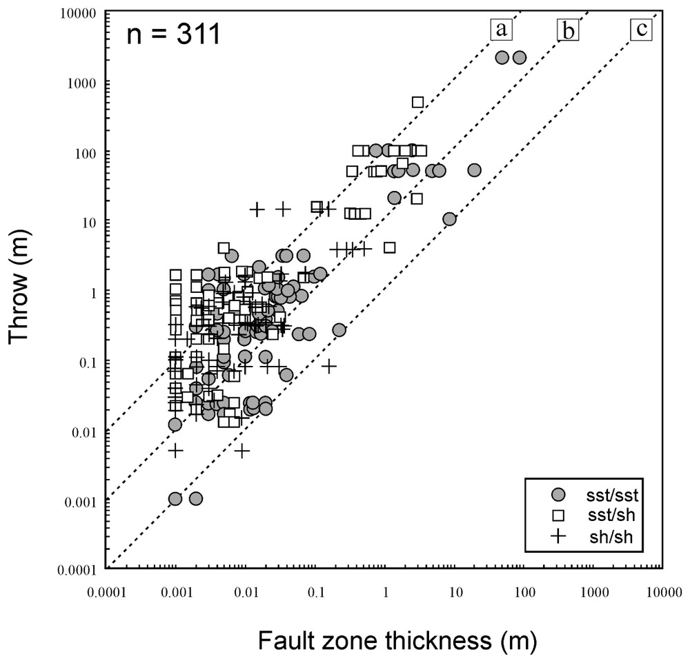
Fault-zone thickness versus fault throw for 311 normal faults from sandstone–shale layers in western Sinai (data from [19]). There is a clear increase in fault-zone (damage zone and core) thicknesses with increasing throws. Sst/sst are sandstone–sandstone juxtapositions, ast/sh are sandstone–shale juxtapositions, and sh/sh are shale–shale juxtapositions.
Épaisseur de la zone de faille en fonction du rejet de faille pour 311 failles normales de niveaux argilo-gréseux de l'Ouest du Sinaı̈ (données extraites de [19]). On observe une nette augmentation de l'épaisseur de la zone de faille (zone de dégât et cœur) en fonction de l'augmentation du rejet. Sst/sst sont les juxtapositions grès–grès, ast/sh les juxtapositions grès–shale et sh/sh les juxtapositions shale–shale.
4 Temporal variation in displacement during fault-zone development
Various field studies indicate that as a fault grows, its L/u ratio becomes smaller. This means that, as the fault evolves, its displacement u becomes larger in proportion to its trace length L (Fig. 4). Although the estimates of fault lengths, particularly for buried faults as in the data set in Fig. 4, are always difficult and generally crude, the data in Fig. 4 illustrate the general observation that fault displacement tends to increase much in relation to fault trace length as the fault-zone evolves. In terms of the present model, the effective Young's modulus that controls the fault displacement (the modulus of the core and the damage zone) becomes gradually lower as the fault evolves, so that, in accordance with Eqs. (1) and (2), the L/u ratio decreases.
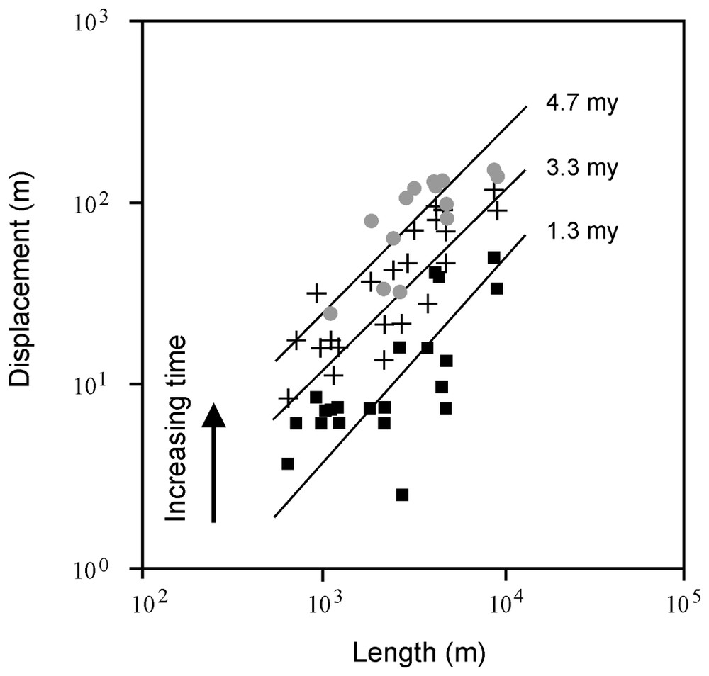
Decrease in trace length (L) and fault displacement (u) ratios during evolution of a Late Miocene syn-sedimentary normal fault population from the Cartier Trough in the Timor Sea of Western Australia. Only the largest 23 faults are shown in this dataset. Filled boxes indicate 1.3 Myr (million years), crosses 3.3 Myr, and grey circles 4.7 Myr from the onset of faulting (data from [26]).
Diminution de rapports longueur de trace (L) et déplacement de faille (u) au cours de l'évolution d'une population de failles normales syn-sédimentaires de la fin du Miocène dans la dépression Cartier de la mer de Timor, Ouest de l'Australie. Seules les 23 failles les plus larges sont considérées dans les données. Les carrés noirs indiquent 1,3 Ma, les croix 3,3 Ma et les cercles gris 4,7 Ma à partir du début de la formation des failles (données d'après [26]).
A related observation is that the L/u ratio on major faults is normally much smaller than the ratio between rupture length Lr and slip s in individual earthquakes. The Lr/s ratio is of the order of 103 to 104 [3,28], whereas the L/u ratio of a major fault is of the order of 101 to 102 (Figs. 1 and 4; [6,7,29]). The Lr/u and L/u ratios thus commonly differ by one or two orders of a magnitude.
In the present model, this difference between instantaneous slip and long-term displacement can be explained in terms of different effective Young's moduli. During an earthquake rupture, it is the dynamic Young's modulus that controls the instantaneous dynamic surface slip on the fault, whereas the long-term static displacement on the same fault is determined by the static moduli. The dynamic modulus is normally greater than the static modulus, particularly at shallow crustal depths where the difference may be by a factor of 13 [11]. Thus, in this model, following each seismic slip there is an aseismic displacement on the fault that is controlled by the static modulus and gradually brings the Lr/s ratio nearer to the L/u ratio. Aseismic slip is common on many faults; for example, it is estimated that in many earthquake areas, such as in subduction and transform zones, around 50% of the slip is aseismic [24, Chapter 5]. In the model presented here, at least part of the aseismic slip is related to displacement adjustment (increase) to a value determined by the static Young's modulus.
5 Spatial variation in displacement during fault-zone development
The spatial effects of Young's modulus on fault displacement can be demonstrated where a single fault dissects rocks of different stiffnesses. Many of the large normal faults in the rift zone of Iceland dissect rocks of very different mechanical properties, namely stiff pahoehoe lava flows and soft layers of hyaloclastite (basaltic tuffs and breccias). The hyaloclastite layers vary in stiffness but are generally much softer than the pahoehoe lava flows that host most of the Holocene normal faults. Crude estimates indicate that the lava flows may be at least 2–3 times stiffer than the mature hyaloclastites, and that the difference may be much greater when the hyaloclastites are newly formed. For example, soft volcanic tuffs can have laboratory Young's moduli of less than 1 GPa, whereas stiff basaltic lava flows have common laboratory values of 30–60 GPa and may reach 100 GPa [1,16].
It follows from Eq. (1) that, for a given length and driving stress (stress drop) of a normal fault, the displacement is inversely proportional to the Young's modulus of its host rock. Thus where the trace of a particular normal fault passes from stiff to soft rocks, its displacement may be expected to increase.
This is exactly what is observed in the rift zone of Iceland. Where the normal faults dissect the Holocene pahoehoe lava flows the throw nowhere exceeds 40 m and is normally only several metres [12]. However, where the same faults dissect hyaloclastite layers, the throw is commonly tens of metres; it may exceed 100 m and is occasionally about 200 m [20]. Although some fault scarps in the Pleistocene hyaloclastites may be older than Holocene, it is unlikely that the age difference between the rocks can account for so large displacement differences. This follows, first, because most faults in the older parts of the Pleistocene seem to complete their growth in less than 10 000 years [10]. Second, many faults dissect hyaloclastite layers only along parts of their trace lengths, and in these layers they show abrupt displacement increases.
6 Discussion
In the past decades, there have been many attempts to find universal scaling laws for fault displacements and their trace lengths [8,21]. If such empirical laws could be found, they would be of great importance in understanding fault development, besides being very helpful in applied fields such as petroleum geology and engineering geology. The fact is, however, that all attempts to find such universal scaling laws have failed.
In this paper I present a mechanical model on the evolution of faults that at least partly explains why universal scaling laws of fault length-displacement cannot exist. The results indicate, first, that faults of a given population but dissecting different rock types, that is, rocks with different stiffnesses, will show different displacements, for a given controlling length, even if the driving stress (stress drop) is the same for all the faults. Thus, regression lines correlating fault displacement (or fracture opening) with trace length for faults in host rocks of contrasting mechanical properties, for example sedimentary rocks and basement rocks of granite or gneiss, will always yield widely different scaling relationships.
Second, the present results indicate that the displacement of a fault changes when it dissects rocks of different stiffnesses. I have illustrated this change by examples from the rift zone of Iceland where the surface traces of large normal faults dissect stiff Holocene lava flows as well as soft Pleistocene hyaloclastites. There are clear indications of abrupt increases in fault displacements where the fault traces pass from stiff basaltic lava flows into soft hyaloclastites.
Third, and perhaps most importantly, the results presented in this paper indicate that the displacement on a fault of a given trace length may change as the core and, in particular, the damage zone of the fault evolve. This implies that sizes of individual slip events on a fault of a given trace length may change with time. For a fault that has little activity, in which case its core and damage zone may become healed and sealed between particular slip events, the core and damage zone could become gradually stiffer (strain hardening), in which case the size of the slip events could remain constant, or even decrease, with time. The focus in this paper, however, is on highly active faults. Then the damage zone and core of the fault are likely to become gradually softer due to more fractures (strain softening), in which case the L/u of the fault would tend to decrease with time, in accordance with observations.
Acknowledgements
I thank Jacques Angelier for very helpful review comments. This work was supported by grants from the Research Council of Norway and the European Commission (through the prepared project).