

Version française abrégée
Nous présentons dans cet article les résultats de travaux expérimentaux portant sur le comportement thermo-poro-mécanique de matériaux prélevés dans la faille active d'Aegion, dans le golfe de Corinthe. Le noyau de la faille, rencontré à une profondeur de 760 m, est constitué d'une zone riche en matériaux argileux sur une longueur d'un mètre environ (Fig. 1). Cette zone est entourée d'une zone de brèche calcaire d'une épaisseur de 3 m, au-dessus, et d'une brèche de radiolarites de 9 m d'épaisseur, au-dessous. L'analyse minéralogique des échantillons a été effectuée par diffraction des rayons X et a montré que, dans la zone de gouge argileuse, les fragments de radiolarites et la matrice argileuse avaient une composition semblable (Tableau 1), à base essentiellement de quartz (74 %), de chlorite (3 %), d'illite (10 %), d'albite (9 %) et d'hématite (3 %).
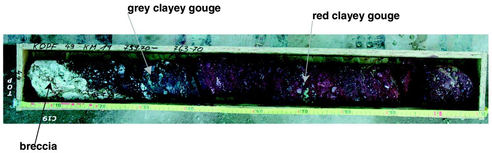
Box 49 containing the core at depth 759.70 m, characterised as the ‘Aegion fault’ core [5].
Boı̂te 49, contenant la carotte prélevée à 759,70 m, caractérisée comme la carotte « faille d'Aegion » [5].
Mineral composition of red fault clayey gouge (after Perdikatsis [7])
Composition minéralogique de la gouge argileuse rouge de la faille (d'après Perdikatsis [7])
| Sample | Quartz (%) | Chlorite (%) | Illite (%) | Albite (%) | Hematite (%) |
| Clay particles<80 μm | 74 | 3 | 10 | 9 | 3 |
| Clay matrix<400 μm | 66 | 2 | 15 | 13 | 3.5 |
| Fragments and gravels | 73 | 2 | 9 | 8 | 2.5 |
Une attention particulière a été portée à la caractérisation du comportement du noyau argileux. En effet, la présence d'argile dans une gouge de faille affecte de manière sensible le comportement de la faille en termes de perméabilité, de réponse mécanique et de réponse thermique, dans la mesure où cette argile, qui est généralement dans un état normalement consolidé, montre une réponse volumique contractante lorsqu'on la chauffe. La courbe granulométrique de la gouge argileuse montre que la proportion des particules fines (de taille inférieure à 80 μm) est de 32 %, tandis que le pourcentage des particules d'argile (fraction de taille inférieure à 2 μm) est de 15 %. Les limites d'Atterberg de ce matériau sont : limite de liquidité, wL=29 %, limite de plasticité, wP=17 %, indice de plasticité, PI=12 %.
Le comportement poro-mécanique est étudié à partir d'essais oedométriques à fortes contraintes (Fig. 3) et d'essais de compression triaxiale à différentes pressions de confinement et différentes températures (Figs. 5 et 6). L'essai oedométrique, largement utilisé en mécanique des sols, permet de caractériser le comportement sur une large gamme de contraintes à l'aide de deux paramètres, l'indice de compressibilité pour la charge et l'indice de gonflement pour la décharge. Il permet aussi une évaluation de l'évolution de la perméabilité en fonction de la contrainte appliquée. Le comportement thermique est étudié à partir d'essais de chauffage sous contrainte isotrope en conditions drainées. Ces essais ont montré qu'une augmentation de la température conduisait à une déformation volumique contractante du matériau (Fig. 7). Ce phénomène d'effondrement, dû au comportement thermique radoucissant de la gouge argileuse, peut conduire à une augmentation de la pression interstitielle, et donc à une diminution de la résistance au cisaillement à l'intérieur de la faille lors d'un cisaillement rapide. Les paramètres thermo-poro-mécaniques déterminés en laboratoire sont résumés dans le Tableau 2.
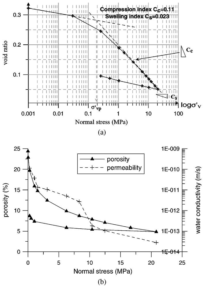
Oedometric compression tests: (a) oedometric curve; (b) porosity and permeability evolution.
Essais de compression oedométrique : (a) courbe oedométrique ; (b) évolution de la porosité et de la perméabilité.
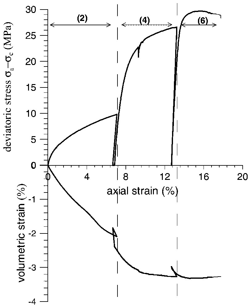
Drained triaxial test performed on the first specimen at room temperature (numbers indicate the loading phases according to Fig. 4).
Essais triaxiaux drainés à température ambiante (les nombres indiquent les phases de chargement, conformément à la Fig. 4).
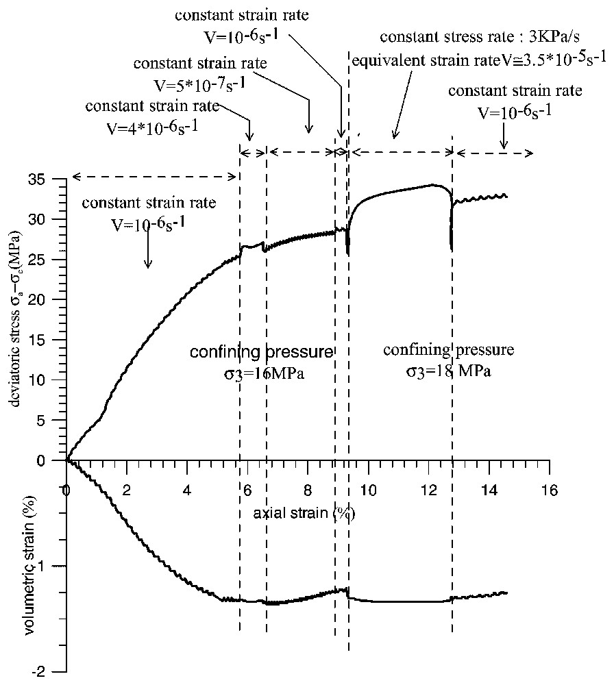
Drained triaxial test performed on the second specimen at 70 °C.
Essais triaxiaux drainés à 70 °C.

Drained heating tests under isotropic state of stress.
Essais de chauffage drainés sous contrainte isotrope.
Thermo-poro-mechanical constants of the water saturated red clayey gouge at a nominal stress of 16 MPa
Constantes thermo-poro-mécaniques de la gouge argileuse rouge saturée en eau à 16 MPa
| Permeability k | 7×10⁻²¹ m2 |
| Compression index Cc | 0.11 |
| Swelling index Cs | 0.023 |
| Consolidation coefficient cv | 2.42×10⁻⁹ m2 s−1 |
| Compressibility coefficient c | 0.0028 MPa−1 |
| Thermal pressurization coefficient λ | 136 kPa °C−1 |
| Friction angle at critical state ϕcs | 28°–29° |
Les conclusions de cette étude sont les suivantes.
- – Le noyau argileux de la faille a une perméabilité très faible (∼10−20 m2) et présente un comportement volumique contractant lors d'une augmentation de la température (radoucissement thermique) ; ainsi, un cisaillement rapide peut conduire à une pressurisation du fluide de la faille.
- – Lors d'essais triaxiaux en conditions drainées à température et confinement constants, le matériau atteint l'état critique (écoulement plastique à volume constant sous déviateur constant) sous compaction monotone.
- – La résistance au frottement du matériau argileux augmente légèrement avec la température et la vitesse de déformation (écrouissage positif en température et vitesse de sollicitation).
- – Le joint entre la zone des calcaires fracturés et les bandes cataclastiques, étudié à l'aide d'essais de cisaillement direct, montre un comportement fragile et contractant, avec un angle de frottement résiduel d'environ 32°, soit 3° de plus que celui de la gouge argileuse.
1 Introduction
Within the frame of the European projects DG-Lab Corinth and 3F-Corinth, fault zone cores from the active Aegion Fault in the Gulf of Corinth in Greece have been collected continuously from depths between 708 to 782 m [5]. At depth 760 m the Aegion Fault was intercepted, dipping at an angle of about 60°. The heart of the fault is a zone of clay-rich material on a length of about 1 m. This zone is surrounded by a damage zone of highly fractured rock (breccia). The fault material is embedded between limestone cataclasite on top with a thickness of about 3 m and radiolarite cataclasite below with a thickness of about 9 m and is characterized as gouge clayey matrix and radiolarite fragments (Fig. 1) [5].
The mineralogical analysis of the samples was carried out by X-ray diffraction techniques. The radiolarites fragments as well as the clay matrix have been studied. Similar mineral composition was found for the fragments and for the clay particles as shown on Table 1 [7]. On this table the mineral composition is normalized to 100%. The amorphous content is about 20%.
In this paper we present results from rock-mechanical laboratory analyses on specimens taken from the Aegion Fault core. Special attention is paid on temperature effects on the behaviour of the clayey core of the lower part of Aegion Fault drilling core. This zone corresponds to the weakest gouge clayey matrix and radiolarite fragments material encountered in this sequence and is recognisable from its red-brown coloration. In addition, results are presented from direct shear tests performed along the interface between the limestone and the cataclastic bands as encountered at depth 744 m.
2 The role of clay minerals in fault zones
The observations from the active fault drilling operation of the Geological Survey of Japan at Nojima Hirabayashi after the 1995 Hyogoken-nanbu (Kobe) Earthquake and the following analysis by Otsuki et al. [6] renewed the interest of the geophysics community on the role of temperature and fluids in active faulting [2,4]. Shear heating tends to increase pore pressure and to decrease the effective compressive stress and the shearing resistance of the fault material. On the other hand, dilatancy tends to decrease pore pressure. Such couplings have been studied thoroughly in a recent paper of Garagash and Rudnicki [1].
Fault zones are often characterized by large amounts of clay minerals, which form well-defined structures within the fault zone. The total concentration of the clay minerals in the fault zone is usually larger than in the host rock. These clay minerals inside the fault gouge are widely believed to affect significantly the mechanical behaviour of faults, since, as is the case for normally consolidated clays, they tend to contract when heated.
Based on the above-mentioned literature and the recent experimental work by Sultan et al. [9], Vardoulakis has demonstrated [12,13] the importance of thermally collapsible and thermally softening clay on the overall dynamic thermo-poro-mechanical behaviour of clay-rich gouges. Accordingly, conditions for possible softening behaviour of the clay under thermal loading are investigated. The sensitive parameter for the description of the thermo-poro-mechanical coupling is the thermal expansion coefficient of the material. Possible collapse of the clay under thermal loading may activate fluid pressurization inside the fault and lead to substantial reduction of the apparent friction.
3 Thermo-poro-mechanical properties of the red Aegion Fault clay
3.1 Samples preparation and in situ stress
In geotechnical engineering special techniques exist to obtain high-quality undisturbed soil samples and try to prevent alteration of soil structure. It is however very difficult to obtain undisturbed samples from great depths. Unfortunately within the frame of DG-Lab project no resources could be made available to use these techniques and the cores have been disturbed to some degree during sampling and transportation. However this is not so detrimental for the type of gouge material that was recovered as it can be with cemented sands or with soft clays.
As the first reports from the drilling site confirm, the clayey gouge that was extracted from Aegion Fault was a remarkably soft material, Fig. 1. Most probably, this is because this material was continuously stressed due to the aseismic and seismic movements of the fault. Thus, it is expected that the effect of remoulding be of lesser importance, as long as the density and the water content of the samples are preserved for testing.
The in situ density of the material is reasonably retrieved by applying the in situ stresses onto the sample. Notice that it is programmed within the DGLab project to perform direct stress measurements inside the borehole. The data are not available at present. Thus the in situ state of stress has to be estimated. Assuming that the density of the overburden is about 2.5 g cm−3, we estimate a total vertical stress of about 19 MPa, which in turn is corresponding to an effective vertical stress of 11.4 MPa.
Once the Aegion Fault core was taken from the borehole, it was stored for a few days on site and then it was transported to the Soil Mechanics Laboratory of ‘École nationale des ponts et chaussées’, Paris, France, where it was stored in a room with controlled temperature and humidity. Obviously, it was not possible to avoid partial drying of the core during extraction, storage and transportation, but then it was regularly wetted as soon as it was stored in good conditions. As it was not possible to use in the experiments the same saturation fluid as in situ, we have used demineralised water in which a certain amount of particles from the sample have been placed during 24 h. The mixture has been then filtered and the resulting fluid has been used for the saturation of the tested samples. This technique is commonly used in soil testing to avoid any chemical influence of the saturation fluid on the mechanical properties of the tested material.
3.2 Particle size characteristics and Atterberg limits of the material
Fig. 2 shows the grain-size distribution curve for the red Aegion Fault clay material. The coarse fraction corresponds to radiolarite fragments. The percentage of fines (fraction smaller than 80 μm sieve size) is 32% and the percentage of clay particles (mass fraction smaller than 2 μm) is about 15%.
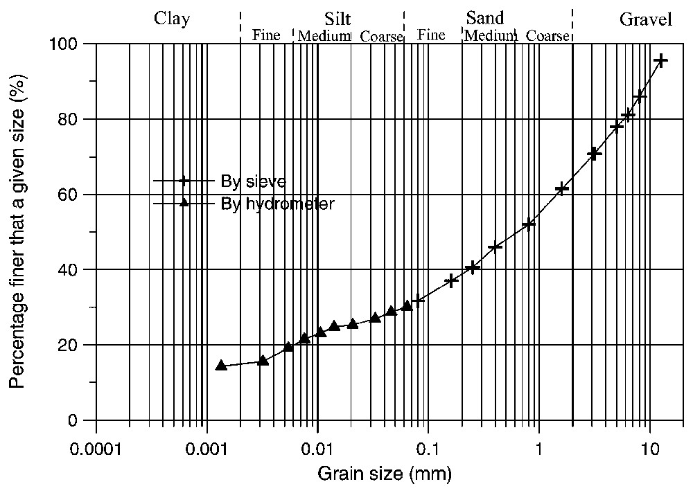
Grain size distribution of the red Aegion fault clayey gouge.
Courbe granulométrique de la gouge argileuse rouge de la faille d'Aegion.
The corresponding Atterberg limits are: liquid limit wL=29%, plastic limit wP=17%, which correspond to a relatively low plasticity index (PI=12%). According to the USC system, the material is classified as a ‘clayey sand’.
3.3 Oedometric compression test
The oedometer test is commonly used in soil mechanics practice to measure compressibility. Here for completeness, we outline the basic concepts of this test: a fluid-saturated cylindrical specimen is confined latterly by a stiff metal ring and the specimen is stressed along the vertical axis. Due to the lateral rigid confinement of the specimen, the strains in horizontal directions are suppressed. Porous stones are employed on the top and bottom of the specimen in order to permit the free drainage of the pore-fluid in or out of the specimen. During the test the vertical load is applied in small increments. For each load increment, the vertical deformation of the specimen is monitored using displacement gauges. Assuming that the grains of the solid constituent are incompressible, all volume changes are attributed to changes in the voids ratio of the specimen and are directly linked with the extrusion of the pore-fluid from the pore-space. Thus we relate the change in the void ratio of the specimen Δe with the volumetric strain εv:
| (1) |
The commonly observed non-linear stress-strain response of a soft geomaterial in oedometric compression makes it more convenient to plot the void ratio versus the effective vertical stress σ′v in a logarithmic scale, because, as was first observed by Terzaghi [11], at large stresses the corresponding curve becomes a straight line, so that a unique parameter, the so-called compression index:
| (2) |
In Fig. 3 are displayed the results from oedometric compression test performed on a saturated sample using a high-pressure oedometer [3]. A system of double cantilever beam allows a maximum vertical load of 12 t corresponding to a maximum stress of about 31 MPa on a cylindrical sample with a diameter of 70 mm. The curve can be divided into two parts. The first part, starting at the beginning of the curve, represents the reconsolidation phase. At the end of the reconsolidation, the curve shows a sharp bend and becomes a straight line, which corresponds to the primary consolidation line of a normally consolidated sample. The vertical stress σ′vp, which corresponds to the elbow of the consolidation curve, marks the point where the sample starts to present large irreversible deformation when loaded. After Casagrande, this stress is identified with the so-called pre-consolidation stress. The small value of the pre-consolidation stress obtained here shows that the material has been remoulded during the coring process and has lost the memory of its past loading history. The measured compression index Cc=0.11 is typical of a sandy clay.
The evolution in time of the compression of a fluid-saturated, fluid-permeable porous material is described by Terzaghi's (1925) consolidation theory. According to it, the compaction of the material is associated with the extrusion of the pore-fluid through the permeable boundaries of the specimen. In the considered one-dimensional setting of a specimen compressed vertically in an oedometer, this theory results into the following equation for the dissipation of excess pore pressure:
| (3) |
| (4) |
| (5) |
By using the Casagrande method [10], it is possible to estimate the consolidation coefficient cv directly from oedometer test results and thus, from Eq. (4), to evaluate the hydraulic conductivity of the gouge as a function of the applied oedometric pressure (Fig. 3). Notice that the physical or Muskat permeability k of the material, with dimension of square length, is related to the hydraulic conductivity kf by:
| (6) |
The oedometer tests have yielded the following values for the consolidation coefficient and the permeability of the tested fault gouge material at σ′v=15 MPa: cv≈2.42×10⁻⁹ m2 s−1, k=7×10⁻²¹ m2.
After the last stage of the loading process at σ′v=21 MPa, the sample was unloaded. The corresponding swelling index is Cs=0.023. The specimen was then removed from the oedometric cell, weighted and then dried in an oven at 105 °C for 24 h. The porosity of the specimen at the end of the test was found to be 8.7%. The evolution of the porosity with axial stress was back calculated from the axial strain measurements, as is shown in Fig. 3b. Thus the back-calculated initial porosity of the material is 19.7% and the porosity of the sample loaded in oedometric compression at σ′v=16.6 MPa is 5.8%.
We notice finally that the oedometer tests allow the determination of the isothermal compressibility coefficient
| (7) |
3.4 Strength parameters from drained triaxial compression tests
Due to the small amount of material available for experimental studies, only two specimens could be used. The first specimen was tested at room temperature (θ=22 °C) and the second at an elevated temperature (θ=70 °C). For the same reason, ‘stepped’ triaxial testing programmes were imposed, following the stress paths shown in Fig. 4.
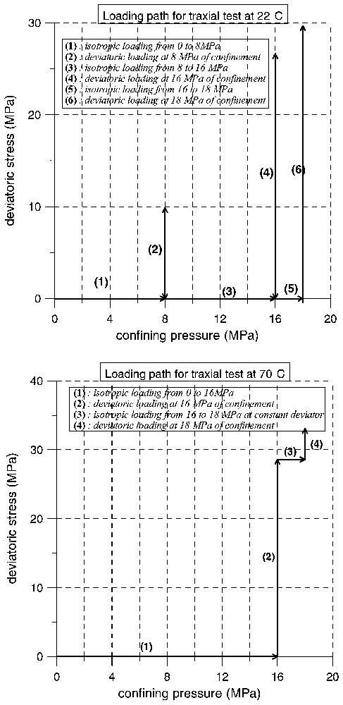
Stress paths followed in the triaxial compression tests.
Chemins de contraintes pour les essais de compression triaxiale.
The first specimen was sheared sequentially at confining pressures σc=8 MPa, σc=16 MPa and σc=18 MPa. At the end of each shearing phase at constant confining pressure, the specimen was unloaded axially and the confining pressure was augmented to reach the next prescribed level. For the second specimen, the axial load was kept constant during the augmentation of the confining pressure from σc=16 MPa to σc=18 MPa. As we are interested here in the response of the material during the shearing phase and considering that the volumetric strains are not significant during the unloading phases (the material is practically rigid upon unloading), the stress paths followed in the triaxial tests of the first and the second specimen do not differ significantly. The corresponding stress–strain curves are shown in Figs. 5 and 6, respectively. Axial and volumetric strains are measured with respect to an initial state, corresponding to the beginning of the first deviatoric phase of the test.
For the 1st specimen, tested at θ=22 °C and σc=8 MPa, the loading phase was interrupted at an axial strain, εa=7.2% corresponding to a deviatoric stress q=σa−σc=9.9 MPa. Since this value of the deviatoric stress is actually smaller than the value, qf, at which failure occurs, the specimen remained homogeneous. This justifies the loading strategy applied here, according to which the same specimen could be used for a different higher pressure. Using a hyperbolic fitting of the data we could estimate that, at σc=8 MPa, qf≈14 MPa. For the shearing phases at σc=16 MPa and at σc=18 MPa, the material was compacting and it reached the critical state of maximum compaction at a mobilized friction angle of φcs=27.9°. For both tested specimens the critical state was reached for large strains. For the first specimen, the maximum volumetric strain (respectively, axial strain) was εv,max≈3.3% (respectively, εa,max≈17.8%). The corresponding values for the second specimen are εv,max≈1.3% (εa,max≈14.5%). We notice that the dilatant behaviour, which is observed at the end of the test, is attributed to the occurrence of shear banding in the sample.
The frictional resistance of the material at critical state increases slightly with the temperature and with the strain rate. The influence of temperature on the friction angle can be judged by comparing the value of maximum friction angle φcs=29°, for second specimen and for a strain rate,
As is shown in Fig. 6, changes in the strain rate during the test indicate also some rate sensitivity. Here we evaluate the rate sensitivity of the tested material in terms of the mobilized-friction coefficient f:
| (8) |
| (9) |
| (10) |
3.5 Drained thermal loading of the clayey gouge
In order to study the effect of temperature on the volumetric behaviour of the material, two tests of drained heating have been performed in isotropic stress conditions. The first test was run with an isotropic effective stress of p′=16 MPa and the second test with p′=12 MPa. For each test, the specimen was first loaded isotropically to its final stress in drained conditions and at constant room temperature. Then by keeping the isotropic stress constant, the specimen was heated in drained conditions at a rate,
| (11) |
| (12) |
| (13) |
| (14) |
3.6 Summary
The Aegion Fault gouge is a clay-rock mixture. The above results have shown that although the clay fraction is relatively small, it has a significant influence on the thermo-mechanical properties of the material. The thermo-poro-mechanical constants of the water saturated red clayey gouge at a nominal axial effective stress of 16 MPa are summarized in Table 2.
4 Mechanical properties of the joint between the fractured limestone and the breccias zone
It is of interest to study the behaviour of the interface between fractured limestone and cataclastic bands as found above the clayey core of the faults (Fig. 8). One sample has been tested in the direct shear box of Laboratory 3S (Soils, Solids, Structures) in Grenoble, France. The orientation of the joint with respect to the axis of the core is 112°. On the side of the vein wall of the fault, the material is a fissured limestone with open fractures often filled with calcite. On the side of the breccia, it is a crushed, relatively porous material with recent cementing. Voids of several millimetres of diameter and geodes with calcite filling are visible inside the calcite where the crystallization is uncompleted.
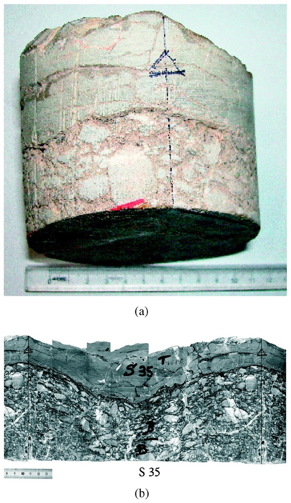
Interface between the fractured limestone and a cataclastic band (Box 33 – Core 13-2) at depth 744 m: (a) core sample; (b) unfolded picture of the core surface.
Interface entre le calcaire fracturé et une bande cataclastique (boı̂te 33 – carotte 13-2) à 744 m de profondeur : (a) échantillon ; (b) développée de la surface.
During the direct shear experiments, the displacement was applied on the joint in a direction that corresponds to the relative movement observed in the Corinth Gulf, i.e., from south to north. The stress path chosen is as follows:
- – first an increasing normal stress was applied with two unloading and reloading cycles at 5 MPa and 10 Pa;
- – then at a nominal normal stress of 12.20 MPa, a shear displacement was applied up to relative tangential displacement Δut=40 mm;
- – then the tangential displacement was reversed to zero relative tangential displacement.
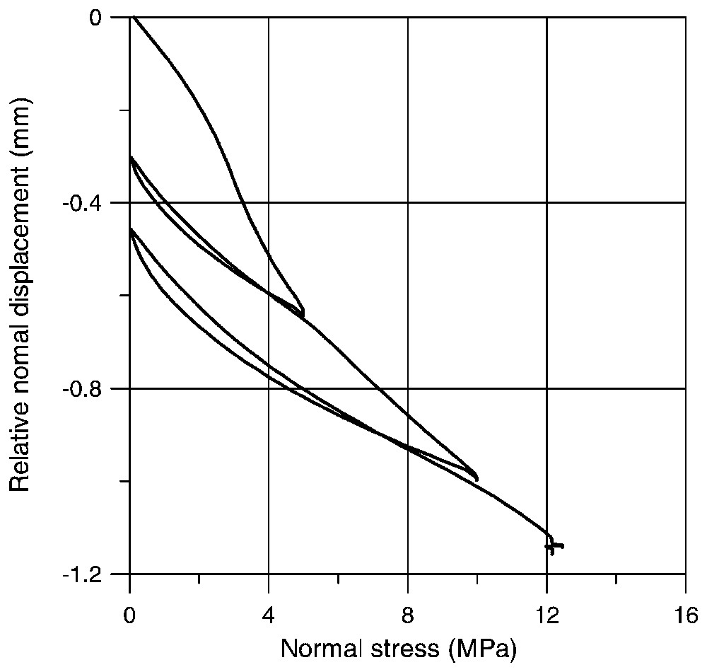
Cyclic normal loading.
Chargement normal cyclique.
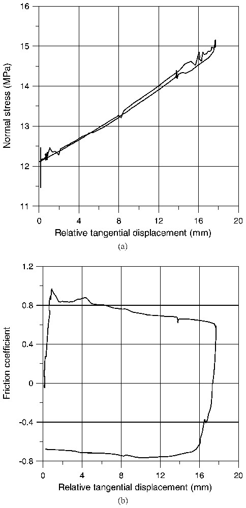
Direct shear experiment under constant normal force: (a) evolution of normal stress; (b) friction coefficient.
Essai de cisaillement direct sous force normale constante : (a) évolution de la contrainte normale ; (b) coefficient de frottement.
The friction coefficient, defined as the ratio between shear stress and normal stress
| (15) |
Important porosity reduction is observed for the first cycle. Notice that pore closure is frequently observed in uniaxial testing of highly porous rocks. The contractant character of the interface, when sheared is shown in Fig. 11. The corresponding dilatancy angle is negative, ψ=−7°, during the loading phase and positive, ψ=5°, during the unloading phase.

Direct shear experiment under constant normal force: contractancy of the joint during shear.
Essai de cisaillement direct sous force normale constante : contractance du joint sous cisaillement.
The mineralogical composition of the crushed material exactly at the contact between the limestone and the breccia (Fig. 12) after the shear test has been analysed using X-ray diffraction and was found as follows.
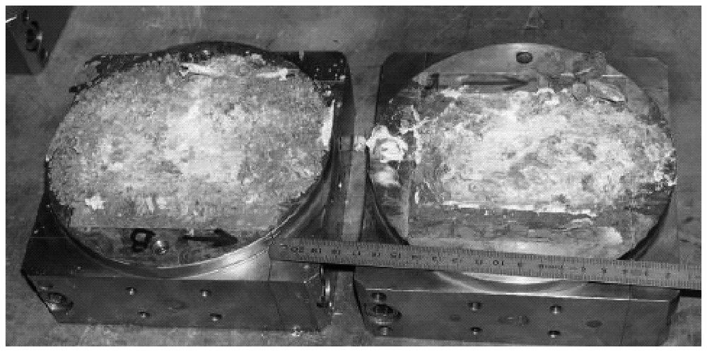
The contact zone between the limestone and the breccia tested in direct shear.
Zone de contact entre le calcaire et la brèche, testée en cisaillement simple.
5 Conclusions
Preliminary results of the experimental characterisation program performed on fault zone cores from Aegion Fault have showed that:
- – the clayey core of the fault has a very low fluid permeability and exhibits contractant volumetric behaviour when heated; thus rapid shear deformation may lead to fluid pressurisation inside the fault;
- – during drained triaxial tests at constant temperature and confinement, the material is reaching under continuous compaction the critical state (i.e., the state of constant volume and constant deviator);
- – the frictional resistance of the material increases slightly with temperature and strain rate;
- – the joint between the carbonate zone and the cataclastic bands shows a brittle and contractant behaviour with a residual friction angle of about 32°, which is higher by 3° than the friction angle at critical state of the clay core.
Further experimental studies including the complete mechanical characterisation of the breccia zone and of the interface between this zone and the clayey gouge will be presented in a near future.
Acknowledgements
The authors wish to acknowledge the EU project ‘DG-Lab Corinth’ (EVR1-CT-2000-40005) for supporting this research. They also wish to thank Prof. V. Perdikatsis (Technical University of Crete, Greece), Dr. E. Carrio and Dr. A. Giraud (University Joseph-Fourier, Grenoble, France), Dr. S. Guedon-Dubied and F. Martineau (‘Laboratoire central des ponts et chaussées’, Paris, France) for their contributions in the X-ray petrographic analysis and geological interpretation of the samples.
Vous devez vous connecter pour continuer.
S'authentifier