

Version française abrégée
1 Introduction
L'augmentation de la pression hydrostatique est un facteur déclencheur et accélérateur des grands mouvements de versants rocheux [15]. Cependant, l'hydrogéologie de ces versants, en particulier celle de la zone basculée décomprimée qui peut s'étendre profondément dans la pente, est mal connue [13]. Les couplages entre hydrogéologie et stabilité des grands volumes rocheux sont aussi très complexes, puisqu'ils résultent à la fois de relations « directes » entre pression et déformation des pores de la roche et de relations « indirectes », correspondant à des changements des propriétés du milieu [16]. Une première tentative d'analyser ces effets couplés est présentée dans ce papier. Elle repose sur des relevés in situ des indices gravitaires et hydrogéologiques, sur la corrélation entre débits infiltrés des précipitations et vitesses de déplacement du versant, et sur une approche par modélisation numérique 2D des couplages hydromécaniques.
2 Les déformations gravitaires du versant de La Clapière
Le versant de La Clapière se situe en bordure nord-ouest du massif cristallin de l'Argentera Mercantour. Il est découpé par trois familles de failles N010°E–N030°E, N080°E–N090°E et N110°E–N140°E, avec des pendages d'environ 90° (Fig. 1). La foliation des gneiss présente un pendage de l'ordre de 20°dans la zone altérée superficielle située entre 1700 et 2000 m d'altitude. Le glissement actuel (volume de 60 millions de mètres cube) est limité vers le haut, à 1600 m d'altitude, par un escarpement de 120 m de hauteur et de 800 m de large. À sa base, il recouvre les alluvions de la Tinée sur 1 km de large (Fig. 1a). La masse en mouvement se compose de trois compartiments : le glissement principal (volume central), qui se déplace de 45 à 90 cm an−1 selon la surface de rupture, le compartiment supérieur nord-est, qui se comporte comme un glissement de blocs et qui vient napper le glissement principal avec une vitesse de 100 à 380 cm an−1, et le compartiment supérieur nord-ouest, non circonscrit par une surface de rupture qui subit un mouvement de basculement de 20 à 70 cm an−1 (Fig. 1b). La surface de rupture se situe à environ 100–200 m de profondeur (Fig. 1c). Le glissement actuel de La Clapière est emboîté dans un mouvement fossile beaucoup plus large, qui se caractérise par un réseau de crevasses et d'escarpements pluri-hectométriques localisés entre 1700 et 2100 m d'altitude. Ces structures ont été générées dans le prolongement des grandes failles qui affectent toute la hauteur du versant par basculement de la partie supérieure de celles-ci au cours de trois grandes périodes : 11 000 ans (déglaciation de la vallée de la Tinée), 7000 ans et 3000 ans [3].
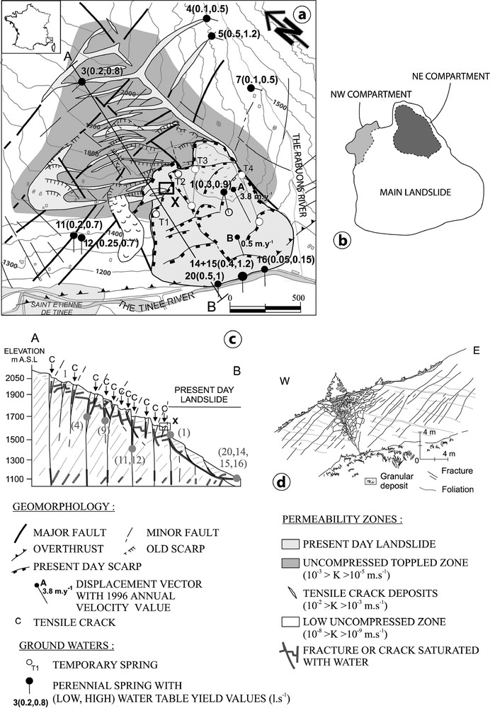
(a) Geostructural, hydrological and landslide context, (b) landslide compartments, (c) hydrogeological cross section, (d) field observation of a tensile crack filled with superficial deposits.
(a) Contexte géostructural, hydrogéologique du glissement de terrain, (b) compartiments composant le glissement, (c) coupe hydrogéologique, (d) observation d'une crevasse en tension remplie de dépôts superficiels.
3 Déformations gravitaires et hydrogéologie du versant
L'hydrogéologie du versant est marquée par la présence de réservoirs emboîtés (Fig. 1a et c). Le glissement actuel est un réservoir rocheux très perméable, dont les fractures déformées par le mouvement présentent des ouvertures pluricentimétriques. Il est drainé, au niveau de la vallée de la Tinée, par les sources pérennes 14, 15, 16 et 20, d'un débit total de 0,95 à 2,35 l s−1, toutes situées dans l'axe d'une zone de faille N010°E, qui coupe le glissement en son centre (Fig. 1a). Dans la zone décomprimée supérieure du versant, le réseau de crevasses avec leur remplissage de colluvions constitue un réseau de petits réservoirs dont les perméabilités sont estimées entre 10−2 et 10−3 m s−1 (Fig. 1d). Ces crevasses sont plus ou moins saturées en eau et sont drainées en permanence entre 1650 et 1400 m d'altitude par les sources 4, 5, 11 et 12, d'un débit total de 0,2 à 1 l s−1. La zone faiblement décomprimée située en profondeur dans le versant affleure localement au fond des vallées, sous l'altitude 1400 m. Il s'agit d'un réservoir rocheux fracturé, de perméabilités faibles, comprises entre 10−8 et 10−9 m s−1. Aucune source n'a été repérée émergeant de cette zone.
L'activation du mouvement actuel de La Clapière se produit dans les années 1950–1955 (Fig. 2a). Il y a ensuite une augmentation constante et non linéaire des vitesses jusqu'au pic de 6 m an−1, en 1987. Après 1987, les vitesses annuelles diminuent sensiblement et présentent de fortes oscillations interannuelles. Les années 1950–1955 sont marquées par des épisodes de précipitations exceptionnelles, qui ont donné lieu à des crues dévastatrices de la Tinée. Ces épisodes pourraient être à l'origine du déclenchement du mouvement. Cependant, il apparaît que d'autres épisodes de précipitations majeurs (années 1922 et 1926) ne produisent pas d'effet sur le versant. De même, le pic de vitesses de 1987 ne se corrèle pas avec un épisode de précipitations exceptionnelles. Après 1987, les fluctuations de vitesse se corrèlent avec les précipitations annuelles [7]. À l'échelle de l'année 1999, il a été montré que les accélérations du mouvement sont synchrones des épisodes d'infiltration d'automne et de printemps, dont les débits varient de 0,7 à 2,8 l s−1 (Fig. 2b, [5]).
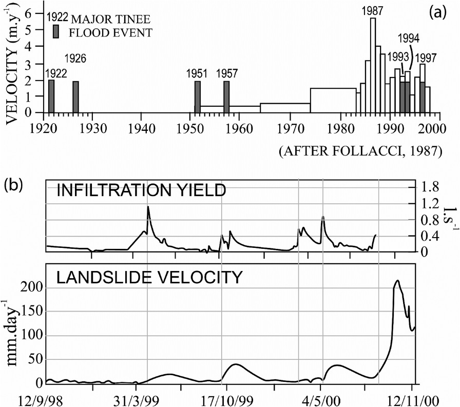
(a) Long-term comparison between La Clapière landslide velocity and Tinée River major flood events (after [7], modified); (b) Correlation between infiltration and velocity variations at the year scale.
(a) Comparaison sur le long terme entre vitesse du glissement de La Clapière et les événements majeurs de crue de la rivière de la Tinée (d'après [7], modifié) ; (b) Corrélation entre infiltration et variations des vitesses à l'échelle de l'année.
4 Modélisation
Deux calculs couplés hydromécaniques ont été menés avec UDEC [6] pour évaluer les effets des infiltrations, à deux stades de déformation du versant : le stade de pré-rupture, correspondant aux années 1920 à 1987, et l'état actuel, avec le déplacement d'une masse rocheuse importante, selon une surface de rupture située à 100 m de profondeur et de pendage 28° vers la vallée (Fig. 3a et b). La géométrie initiale du versant comporte les failles verticales majeures cartées sur le terrain et un réseau de joints sub-horizontaux pour figurer très schématiquement la foliation des gneiss. Une nappe perchée est simulée entre 1500 et 2000 m d'altitude. Les tests consistent à étudier les déplacements induits par une infiltration de 0,75 l s−1 à 1900 m d'altitude. Dans la simulation pré-rupture, les pressions hydrostatiques dans la nappe perchée varient de 0 à 1 MPa (Fig. 3a). Les déplacements induits affectent tout le versant et principalement la zone située entre 1100 et 1900 m d'altitude. Un bombement se produit à la suite de déplacements horizontaux ou dirigés vers le haut, compris entre 0,1 et 1,3 m. Au-dessus de 1900 m, il se produit un affaissement, avec des déplacements plus faibles, de l'ordre de 0,05 m. Les mêmes résultats apparaissent avec la simulation post-rupture (Fig. 3b). Cependant, les pressions hydrostatiques et les déplacements induits sont plus faibles, car la rupture en pied de versant « améliore » le drainage de celui-ci. L'orientation des déplacements parallèle à la surface de rupture traduit la prédominance du mécanisme de glissement dans cette zone.
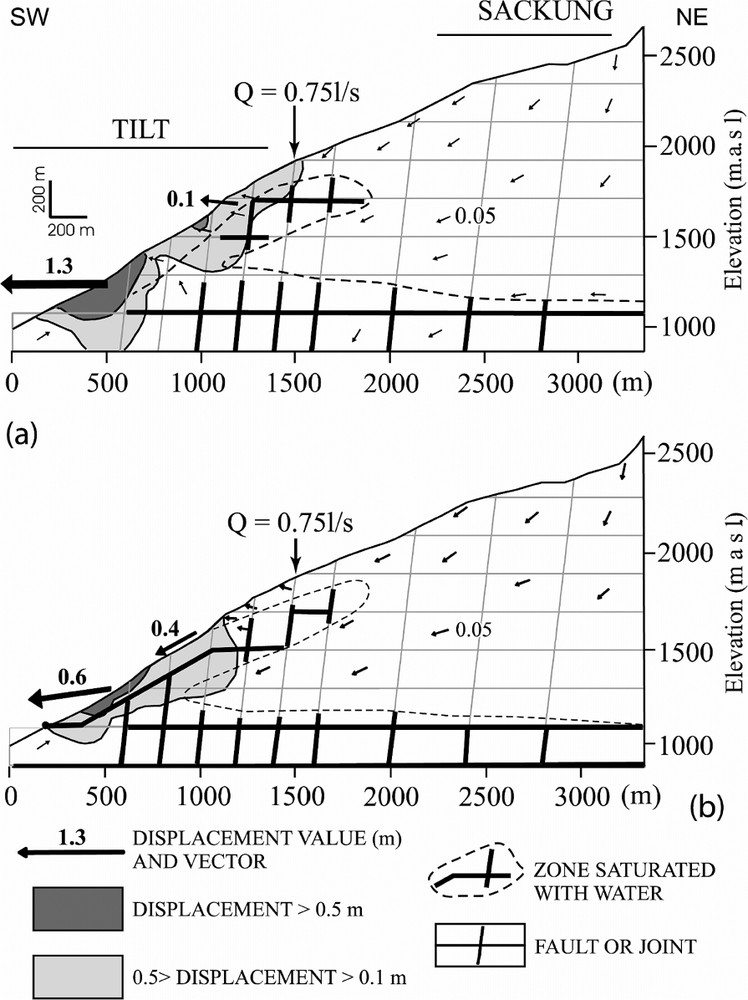
Results of coupled hydromechanical modelling: (a) Model ‘A’, only with pre-existing faults; (b) Model ‘B’, with pre-existing faults and a 28°-dipping failure surface.
Résultats de la modélisation couplée hydromécanique : (a) Modèle ‘A’ seulement avec les failles préexistantes, (b) Modèle ‘B’ avec les failles préexistantes et une surface de rupture inclinée de 28°.
5 Conclusion
Le glissement actuel de La Clapière correspond à la réactivation d'un mouvement ancien de basculement de colonnes de roches de 150 à 200 m d'épaisseur, limité par les failles majeures du versant (Fig. 4a). Ce basculement a généré des structures en crevasses, dans lesquelles les dépôts de pente ont été piégés. Ces remplissages constituent des réservoirs aquifères interconnectés, qui contiennent une nappe perchée en partie haute et médiane de la pente. Les variations de pression hydrostatique de cette nappe accentuent le phénomène de basculement jusqu'à la rupture générale. Dans le cas de La Clapière, la rupture se produirait en 1987 (Fig. 4b, [7,19]). Les calculs numériques montrent qu'une infiltration modérée (de l'ordre du débit moyen interannuel) dans cette nappe perchée suffit à déstabiliser l'ensemble du versant. Après la rupture, la surface ainsi créée et la forte déstructuration de la masse mobilisée favorisent le drainage du versant (Fig. 4c). Il en résulte un abaissement des pressions hydrostatiques, qui induit une diminution des vitesses des mouvements. Ce modèle de couplage entre hydrogéologie et déstabilisation d'une pente rocheuse se retrouverait à différents stades d'évolution sur d'autres mouvements [1,2,4,12,14,18]. Les chroniques de mesures existantes à La Clapière tendraient à montrer que cette évolution se déroule sur un cycle d'au moins 2000 à 3000 ans. Il apparaît que la présence d'eau perchée dans les parties supérieures pré-déstabilisées des grandes fractures d'un versant rocheux augmente fortement les conditions de rupture par basculement.

Schematic model of a mountainous rock slope destabilization under hydrogeological loading.
Modèle schématique de la déstabilisation d'un versant rocheux montagneux sous chargement hydrogéologique.
1 Introduction
In the case of large gravitational mountainous rock slopes, water pressure elevation is one of the major factors triggering and increasing slope instability [15]. We address the problem of how to link localized hydromechanical (HM) effects with generalized slope destabilization, and to estimate what kind of infiltration event can produce sufficient HM non-reversible deformations [11]. First, the hydrogeology of the uncompressed zone that can extend deep in the slopes is not well known, except the fact that such a structural zone can allow high-yield groundwater flows parallel to the slope [13]. Second, couplings correspond to complex mechanisms. ‘Direct’ couplings occur through deformation and pore–fluid interactions and ‘indirect’ couplings imply changes in material properties [16]. It is obvious that such a detailed investigation is hard to conduct in large-scale dangerously moving media. We present in this paper a first attempt to analyse couplings between hydrogeology and stability, taking the example of the well-documented La Clapière landslide (France). Our study relies on a very detailed field mapping of geometrical relationships between hydraulic and gravitational structures of the slope and of time relationships between the current landslide velocities and precipitation. Then, a 2D HM numerical model is used to discuss our field results.
2 The La Clapière slope gravitational deformation
The La Clapière slope is situated at the northwestern edge of the Argentera–Mercantour metamorphic unit (Fig. 1). This basement unit underwent polyphased tectonic deformations during Variscan and Alpine orogeneses [9]. The foliation of the La Clapière slope dips gently (less than 20°) either to the northeast or to the southwest [9]. Between 1700- and 2200-m elevations, metamorphic rocks are weathered in a zone from 50- to 200-m thick. Three sets of faults can be distinguished, trending N010°E–N030°E, N080°E–N090°E, and N110°E–N140°E, with nearly vertical dips (Fig. 1).
The landslide rock mass (estimated volume about 60 million cubic metres) overlaps the Quaternary alluvial deposits of the Tinée River (Fig. 1a). At the top of the landslide is a 120-m-high scarp that extends over a width of 800 m at an elevation of 1600 m. The landslide itself is divided into three main compartments, limited by pre-existing faults (Fig. 1b). Based on cross-sectional geometry, the depth of the failure surface may not exceed 100 to 200 m (Fig. 1c). The main central volume is bounded by the main failure surface. It moves downward at a velocity of 45 to 90 cm yr−1 towards directions N010°E and N115°E. The upper northeastern compartment (5-million-cubic-metre volume) behaves like a block landslide sliding along its own failure surface and overlapping the main landslide, with downward velocities of 100 and 380 cm yr−1. The upper northwestern compartment is bounded to the south by the 150-m-high scarp of the main landslide failure surface and to the north by a 50-m-high scarp. This compartment behaves like a fractured rock mass, with active tension cracks and velocities ranging from 20 to 70 cm yr−1. It is not certain that this compartment should be included in a failure surface at the present time. The present-day La Clapière landslide is nested in a larger unstable slope which has been active (Fig. 1). This unstable slope is characterized by extensional deformation structures like large tension cracks and several meters high downhill scarps located between 1700- and 2100-m elevations. These landforms involve displacements along penetrative pre-existing tectonic joints consistent with gravitational movements that could be linked to a general toppling of the upper part of large rock columns bounded by major penetrative faults. Tension cracks correspond to a metre-scale horizontal opening of the superficial part of the faults that induce a 10- to 50-m-deep trench. Scarps correspond to shear displacements with a vertical throw ranging from 1 to 50 m. These movements occurred during three main pulses 11 000 years ago, 7000 years ago and 3000 years ago [3].
3 Gravitational deformations and slope hydrogeology
Three nested discontinuous fractured reservoirs characterize the slope hydrogeology. Water flows into fractures whose openings depend on the depth and on the gravitational structures of the slope. Gneisses can be considered as impervious [5]. The current landslide can be taken as a highly permeable fractured reservoir, because the displacements induce the formation of large pores inside opened fractures, breccias and blocks. The landslide is drained at its foot by a group of perennial springs (springs 14, 15, 16, 20 in Fig. 1a) with a total discharge comprised between 0.95 and 2.35 l s−1. The springs rise at the bottom of a major N010°E-trending major fault zone that cuts the middle part of the main landslide. A perennial spring (spring 1) rises at the foot of the northeastern compartment at elevation 1550 m, and has a discharge between 0.3 and 0.9 l s−1. After long precipitation periods, some temporary springs (springs T1 to T3) rise around 1550- to 1650-m elevation along faults or at the bottom of major tension cracks filled with colluvial deposits (spring T4). All the streams that originate from the springs located in the upper part of the landslide are interrupted a few hundred metres downstream. This means that all the waters reinfiltrate in the main landslide. Outside the landslide, the slope can be divided into a decompression toppled zone and a low uncompressed zone at depth. The decompression toppled zone is a highly fractured area where tension cracks create linear drains, with estimated permeabilities ranging between 10−2 and 10−3 m s−1 (permeability estimations are done from analytic interpretations of the yield variations of springs using Goodman's formula [8]). Many of the cracks are filled with colluvial deposits, which constitute small reservoirs with an interstitial porosity. These tiny reservoirs are interconnected via the tension-crack network. It is possible to look in detail at colluvium filled cracks, because some of them are cut by the present-day La Clapière main scarp (for location see black rectangle X near the spring T2 in Fig. 1a). Typically, the filling has a 4- to 20-m-wide triangular geometry and an average of 500-m length (Fig. 1c and d). It consists of blocks of various sizes whose arrangement defines rough bedding. The bedding is warped, showing that sedimentation occurred while gravitational movement was active. The deepest part of the filling often consists of very thin deposits of a buried soil that collapsed when the tensile crack was formed. Blocks and sands that can be found in the upper part of the deposits come from the fractured edges of the crack and from glacial deposits that previously covered the slope. The crack extends inside the slope, because it is the superficial reactivation of a tectonic fault. Depending on the places, the colluvial fillings can be completely dry or can be drained by a perennial spring (springs 3, 4 and 5 in Fig. 1a). In the first case, water infiltrating in the colluvial deposits is drained deeper in the slope through the underlying tectonic fault. In the second case, water is trapped in the filling because the basal buried soil is locally impervious. The interconnection of the fillings creates a perched perennial saturated zone that could explain the presence of springs in the upper part of the slope between 1650 and 1400 m in the Tinée Valley slope (springs 11 and 12 with a discharge ranging between 0.1 and 0.4 l s−1) and in the Rabuons Valley (springs 4, 5, and 6, with a discharge ranging between 0.1 and 0.6 l s−1). The low uncompressed part of the slope is outcropping on the Rabuons, the Tenibres and the Tinée River banks below the elevation 1400 m. This zone is fractured by major tectonic joints and can be considered as a relatively low-permeability fissured reservoir (10−8 to 10−9 m s−1, data from neighbouring tunnels inflows interpretation [13]). There is continuity between the joints and the tensile cracks mapped in the uncompressed toppled zone. No springs were mapped coming from this zone.
In order to characterize long-term coupling between hydrology and stability of the slope, we compared historic records of Tinée River flooding (French Ministry of Agriculture database) to landslide annual velocities (French Ministry of Equipment database) since 1920 (Fig. 2a). The activation of the current La Clapière movement begins around the years 1950–1955. From 1951 to 1987, there is a steady non-linear velocity increase up to a 6-m yr−1 peak. After 1987, there is a small decrease in velocities that show annual variations ranging between 4 and 2 m yr−1. During the 1920–1999 period, there are Tinée major flood events corresponding to major precipitation events that caused numerous damages to the valley landscape. Clearly, La Clapière movement triggering fits with 1951–1957 major floods. However, 1922 and 1926 flood events did not cause any slope destabilization, and the 1987 velocity peak does not correspond with any major flood event. For the 1987 to the current period, speed fluctuations roughly fit with annual precipitation fluctuations [7]. At the year scale and for recent years (since 1998), a reconstitution was performed using hydrogeochemistry of spring waters [5]. Cappa et al. [5] show that the spring-water chemical signal presents transient changes occurring directly after precipitation events. From water chemical signal, the amounts of infiltration yields were inferred. There are two main infiltration peaks that correlate with long-duration moderate precipitation amounts (for example, 426 mm/30 days during the 03/1999 period) or with short duration high precipitation amounts (for example, 122 mm/2 days during the 18–22/10/1999 period). For a 0.6-km2 infiltration area, such amounts correspond to precipitation yields respectively ranging from 0.7 to 2.8 l s−1. Landslide velocity curves show accelerations that range from 0.02 to 0.25 mm day−1 (Fig. 2b), synchronous with the infiltration peak periods. Velocity curves have an asymmetric shape with a rapid rise synchronous with the increasing part of the infiltration yield curve (main groundwater infiltration) and a slow decrease synchronous with the decreasing and the drying-up part of the infiltration yield curve (slope drying-up). The duration of acceleration periods is about the same as for infiltration periods.
4 Modelling couplings
We performed two parametric simulations with the UDEC code [6] in order to estimate water infiltration influence during the initial 1951–1987 behaviour of the slope and during the current post-1987 seasonal behaviour of the slope. The UDEC numerical code calculates the bi-dimensional effects of stress on fluid flow, and allows conversely large finite displacements/deformations of a fractured rock mass under pressure loading [6]. We considered a vertical cross-section oriented NE–SW, perpendicular to the topographic surface and extending from the slope crest (2600 m asl) to the Tinée Valley (1100 m asl). In the first test (Model A), only pre-existing fractures were taken into account (Fig. 3a). In the second test (Model B), a 28°-dipping failure surface was set at the foot of the slope (Fig. 3b). We considered for both tests nine discrete penetrative vertical fractures that represent the major faults mapped on the site. So as to hydraulically connect faults between them and to approximate foliation plane geometry, horizontal joints were included in the model. The grid point is made up of triangular mesh elements whose sides are 100 m. This cross-section is constrained by no bottom vertical and no lateral displacements boundary conditions, and, by impervious hydraulic boundary conditions. Rock matrix mechanical behaviour is taken as linearly elastic and isotropic. Faults are assumed to behave according to an elasto-plastic law with the Mohr–Coulomb failure criterion (Table 1). Fault and matrix mechanical and hydraulic parameters are deduced from laboratory and field measurements (Table 1) [5,10]. Parameters are the same for the two tests.
Hydromechanical properties of rock matrix and fractures
Propriétés hydromécaniques de la matrice rocheuse et des fractures
| Rock matrix | Gneiss | Alluvium |
| K (Pa) | 5.3×10¹⁰ | 2.9×10⁹ |
| G (Pa) | 2.5×10¹⁰ | 1.3×10⁹ |
| 2200 | 1500 | |
| Fractures | Vertical faults | Horizontal joints |
| 1.8×10¹⁰ | 1.8×10¹⁰ | |
| 1.8×10⁹ | 1.8×10⁹ | |
| 30 | 30 | |
| 1×10⁻³/1×10−4 | 1×10⁻³/1×10−4 |
The perched saturated zone is simulated, affecting a locally zero permeability at fault segments corresponding to the basal boundary of this zone (dashed line between 1500- and 2000-m elevation; Fig. 3). We performed a static hydromechanical calculation with steady-state flow without consideration of the time (only initial and final calculated equilibrium solutions are compared). The cross-section is first consolidated to gravity until stress and displacements are numerically stabilized (Stage 1). Second, initial groundwater conditions were simulated in the basal saturated zone (Stage 2). No interstitial pressure was set in the perched saturated zone. Then, a 0.75 l s−1 effective infiltration (this value is reported to the average length of a tensile crack reservoir, which is 500 m) is simulated in the slope at 1900-m elevation (Stage 3) (Fig. 3). On the cross-section, we plot maximum displacements induced by the hydraulic loading of Stage 3 (Fig. 3). These plotted displacements correspond to the end of the calculation when the hydromechanical state is stabilized.
In the initial slope case (Model A, Fig. 3a), final calculated pressures are 1 MPa in the perched aquifer. In the basal aquifer, a 0.5-MPa piezometric bump extends from 300 to 1500 m along the x-axis. The maximum calculated values of displacement vector are located between the foot of the slope at 1100 m and the middle part of the slope at 1900 m. This strain zone extends from 50 to 400 m inside the slope. Displacements values vary between 0.1 m and 1.3 m in this zone. High water pressures compared to the hydrostatic pressures are situated in two distinct zones that hydraulically communicate with each other: a basal 500-m thick zone with interstitial pressures ranging between 0 and 5 MPa, and a perched 200-m thick zone with interstitial pressure ranging between 0 and 2-MPa. In the middle part of the slope, there is swelling with vectors dipping towards the top linked with mechanical opening of fractures under pressure increase in the perched saturated zone. In the upper part of the slope, there is a lowering generally called ‘sackung’ [1] with vertical vectors dipping.
The same results are observed in the current slope case (Model B, Fig. 3b). Pressure values are less important and the saturated zones are less extended inside the slope. This means that the slope is better drained after the failure has occurred, because the failure surface increased the connectivity of the previous fault network. As a matter of fact, displacement values are less important. Pressures along the failure plane range from 0 MPa at 1500 m to 0.05 MPa at 1150 m. Displacement maximum values of 0.4 to 0.6 m concentrate along the failure plane where vectors are parallel to the plane. However, a 0.1-m displacement zone extends further in the stable part of the slope, in relation with the basal piezometric bump hydromechanical effect. All the remaining of the slope is also affected by displacements values ranging between 0 and 0.05 m. These upper displacements belong to a deep displacement field generated by the slope foot sliding (mass loss).
The 35% differences between calculated (0.4 to 0.6 m) and measured (0.45 to 0.9 m) annual displacements for Model B can be explained in different ways: the non-consideration of 3D effects, the large heterogeneity of the medium that is highly simplified to a few major fracture planes, and the overestimation of infiltration yield. Such differences imply that caution needs to be exercised when using the results of such numerical models that only aim at a better understanding of the slope behaviour.
5 Discussion and conclusion
The current La Clapière landslide is ‘only’ one more reactivation of larger and older slope movements. The oldest known movement could have been triggered by the last deglaciation. Such initial movements correspond to large-scale toppling of the upper part of rock columns bounded by major vertical discontinuities of the slope (Fig. 4a). It has been shown at Séchilienne [18], Rosone [2], or more theoretically [12,14,17] that toppling can cause tensile crack opening in the upper part of a slope with ‘sackung’ and ‘swelling’, with the creation of counter-ridges downslope. Deep inside the slope, failure can be initiated at the column base. We show in this study that tensile cracks are filled with local material of the slope and that they constitute perched reservoirs at the boundaries of the toppled columns. Hydrostatic pressures are concentrated in the middle and upper parts of the slope, where a relatively low infiltration yield (mean inter-annual value for example) can cause sufficient hydrostatic pressure increase in the cracks to increase rock column destabilization (Fig. 4b). Tilting at the column surface and failure propagation deep in the slope can be generated roughly from the theoretical bottom of the perched aquifer down to the slope foot. At La Clapière, such a failure through tilt could have worked until 1987, when it is thought [7,19] that a general failure surface was created. It could be still going on at Séchilienne and Rosone. When a major failure surface is generated, a large mass slides downslope (Fig. 4c). The slope drainage becomes more active through this failure surface, and there is a general lowering of the hydrostatic pressures in the slope. The perched aquifer is partly drained by the landslide, and, conversely, water coming from this aquifer imposes pressure increases in the upper segments of the landslide failure surface, which are closer to failure than the lower parts (where the stress state is high and the segment dip is low or 0). In regions with moderate seismicity, such typical rock slope gravitational structures [1,4], like ‘sackung’ at the top and ‘swelling or scarp’ at the foot, can then be activated in a few tens of years under precipitation-induced periodic hydromechanical effects. The main conducting parameters of the instability appear to be the slope angle and height, the dip and the spacing between the major penetrative discontinuities, previous gravitational history of the slope and hydrostatic pressures values in the perched aquifer.
Acknowledgements
The authors sincerely thank Dr Christopher Wibberley for his review and constructive comments. Contribution No. 661 of the ‘Géosciences Azur’ Lab.