

1 Introduction
Since 1980 (Gérard et al., 1984; Gérard and Kappelmeyer, 1987), the EGS project at Soultz (France) goals to experiment and develop a new geothermal technology. After an initial Hot Dry Rock (HDR) concept of artificial fracture creation in a homogeneous rock by hydraulic fracturing, the concept at Soultz has progressively evolved to an Enhanced Geothermal System (EGS) where reservoir development involved the reactivation of the preexisting fractures in the granite (Evans et al., 2005; Gérard et al., 2006). Thus, a good knowledge and geometrical characterization of the rock mass and, particularly, of the fracture network are essential for many reasons, from the optimization of the borehole design to the understanding of the flow distribution at depth. At Soultz, this fracture network is structured at different scales, from major fracture zones cross-cutting the granite batholith to intracrystalline microfractures, which induce weakness in the rock mass (Dezayes et al., 2000).
The principle of the EGS technology consists in increasing the low natural hydraulic performance of the geothermal reservoir by hydraulic or/and chemical stimulations. These stimulations increase the permeability so as to allow transport of the geothermal brine. This allows circulation between the wells by using the preexisting fracture network for an efficient extraction of the geothermal fluid. The hydraulic stimulation consists in injecting water with high flow rate in order to increase the pore pressure within the rock mass which promotes the shearing of existing fractures, a mechanism accompanied partly by detectable induced microseismicity. When the injection is stopped, the shearing is irreversible and the reactivated fractures do not close totally, yielding to a new and/or enhanced permeability (Gentier et al., 2000). This mechanical effect of enhanced permeability occurs either in the well near-field or at some distance far from the well. Chemical stimulation affects permeability essentially in the direct well vicinity and consists in injecting acids to dissolve the mineral fillings within the natural fractures, like calcite, secondary silica or clay minerals (Portier et al., 2009). Both methods have to be associated to increase fluid pathways within the fracture network (Nami et al., 2008).
Several studies have shown that some fracture zones are water-bearing prior to stimulation (Vuataz et al., 1990; Genter et al., 1995) and form the main flow channeling after stimulation and during circulation (Sanjuan et al., 2006; Evans et al., 2005). These fracture zones are probably reactivated by shearing whilst in hydraulic stimulation. Moreover, other fracture zones not permeable prior stimulation have been reactivated during the stimulation and have been taking into account in this study.
Thus, fracture zones form the main potential fluid pathways connected to the dense network of mesoscale fractures to form the geothermal reservoir, which is about 1125 km3 for the upper reservoir and 8 km3 for the deeper reservoir, based on induced microseismicity study (Cuenot et al., 2006).
This article presents a characterization of the intermediate scale to large-scale fracturing, formed by fracture zones, in order to make a geometrical update of the fracture database likely to support conductive fluid flow. The goal of this study is to assess the geometry of the fracture network for a better understanding of the fluid circulation in a deep fractured granite reservoir dedicated to geothermal exploitation. The fracture zones presented in this paper correspond to the initial potential conductive network. These results are used for modeling the hydraulic stimulations and circulations of Soultz geothermal reservoir (Sausse et al., 2010; Rachez et al., 2006; Baujard and Bruel, 2005; Kohl and Megel, 2005).
2 Geological and structural context
The Soultz site is located within the Upper Rhine Graben, which is a Cenozoic rift structure belonging to the West European Rift System (Fig. 1; Ziegler, 1992). The filling sediments are marine and lacustrine limestones, marls and evaporites, including the petroleum layers of Pechelbronn, overlaying in unconformity the Jurassic limestones and the Germanic Trias (Fig. 1b). These Cenozoic and Mesozoic sediments have been deposited on the Paleozoic basement, which includes porphyritic monzogranite and two-mica granite (Genter et al., 1999; Stussi et al., 2002; Cocherie et al., 2004; Hooijkaas et al., 2006).
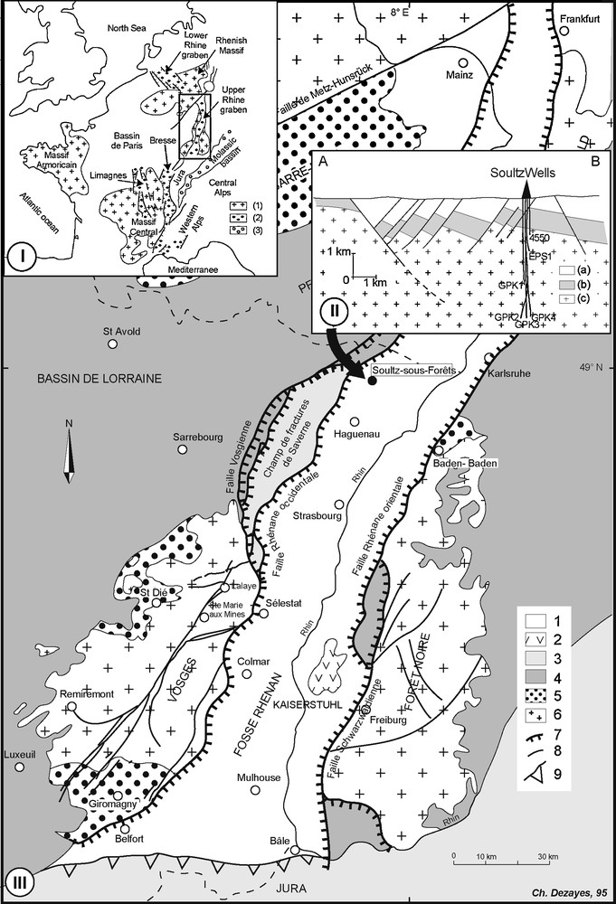
Location of the EGS Soultz site and geology of the Upper Rhine Graben. (I) Location of the Upper Rhine Graben with the West European Rift System. (1) Hercynian basement; (2) Tertiary basins; (3) Alpine molasse. (II): West–east cross-section through the Rhine Graben border and the Soultz site. (a) Cenozoic; (b) Mesozoic; (c) Hercynian basement. (III) Geological and structural map of the Rhine Graben (1) Cenozoic sediments; (2) Cenozoic volcanics; (3) Jurassic; (4) Triassic; (5) Permo-Carbonifeous basins, (6) Hercynian basement; (7) boundary faults; (8) other faults; (9) overthrusts.
Localisation du site EGS de Soultz et géologie du Fossé rhénan supérieur. (I) Localisation du Fossé rhénan supérieur dans le Système de Rift Ouest-Européen. (1) Socle hercynien ; (2) bassins tertiaires ; (3) molasse alpine. (II) Coupe est–ouest passant par la bordure du Fossé rhénan et le site de Soultz. (a) Cénozoïque ; (b) Mésozoïque ; (c) socle hercynien. (III) Carte géologique et structurale du Fossé rhénan (1) remplissage cénozoïque ; (2) édifices volcaniques cénozoïques ; (3) Jurassique ; (4) Trias ; (5) bassins permocarbonifères ; (6) socle hercynien ; (7) failles bordières ; (8) autres failles ; (9) chevauchements.
This granite unit is the target of the geothermal project and hosts the geothermal reservoir. This massif underwent a multiphase tectonic history including Hercynian and Alpine orogeneses. The Cenozoic tectonic history is reflected by the orientations of the current structures forming the Upper Rhine Graben (Fig. 1). The regional major border faults mapped on surface or derived from petroleum seismic reflection studies within the Upper Rhine Graben show a N0-30°E direction in relation to the three main directions of the graben (Fig. 1). In the southern part of the graben, the main direction is about N10°E. This direction rotates clockwise at the center of the graben to N30-25°E and becomes N0°E in its northern part. The Rhenish fracture orientation was formed during the Oligocene opening of the Rhine Graben (Villemin and Bergerat, 1987), reactivating probably some Hercynian structures (Illies, 1972; Illies, 1975; Rotstein et al., 2006). At the Soultz site, the Upper Rhine Graben rotates and the regional border faults are N45°E oriented. This direction is also present in the Triassic sediments in the West of the graben fault, in the Vosges area (Menillet et al., 1989).
However, the granitic basement has been affected by ante-Cenozoic tectonics, particularly the Hercynian orogen. The strike of the major dislocations delimiting the different Hercynian tectonic blocks is roughly N60°E (Fig. 1). At local scale, around the Soultz site, geological mapping, borehole data and interpretation of seismic profiles acquired during the exploration of the Pechelbronn oil field give lots of data to characterize the major fault system (Foehn, 1985; Place et al., 2010). These data were compiled to build a 3D geological model of the sedimentary cover (Renard and Courrioux, 1994; Castera et al., 2008). These studies show that in the sedimentary cover, the faults have a N20°E strike, i.e., a Rhenish direction (Fig. 1). In map view, the faults have a trace length of about 2 to 20 km and occur with a spacing range of about 800 m to 3 km (Valley and Evans, 2007). At depth, below the Soultz site, a horst structure is present and the top of the basement is at 1.4 km depth (Fig. 1b). Within this horst structure, some local faults are detected on the seismic profiles, which are mainly dipping to the west (Fig. 1b).
3 Methodology
Unwrapped borehole image logs and cores studies allow to characterise the fracturing within the Soultz granite at various scales. In the cores, all the fractures are systematically sealed by hydrothermal filling but only 20% of them are visible on the borehole images (Genter et al., 1997). However, only one borehole (EPS1) is fully cored and some spot coring are available in other wells. But the borehole images are suitable for detecting and measuring the orientation of the mesoscale fractures and fracture zones.
On the borehole images, fracture orientations are sometimes difficult to measure due to the fact that fractures are not perfectly planar as it is assumed for the dip calculation. Also, as mentioned above, fracture zones are complex and their orientation is difficult to define. Often, several individual fracture traces are visible on the log image within a given fracture zone, which include brecciated to microbrecciated zone. To determine the fracture zone overall orientation, we consider that the orientation of the border of the brecciated zone is representative of the overall orientation if this limit is well visible and defined and if it forms a well-marked planar structure. However, when several planar structures are present and roughly parallel, we assumed that the orientation of the fracture zone is well approximate with the 3D average orientation of the individual planes.
In order to better characterize low permeable fracture zones, we use the geological database based on petrographical description of cuttings, borehole image log and geophysical log analyses, as calliper, spectral gamma ray and drilling parameters (Fig. 2). The spectral gamma ray data, such as potassium, thorium and uranium contents, are used to detect radioactive element concentration due to the hydrothermal alteration of fracture zones.
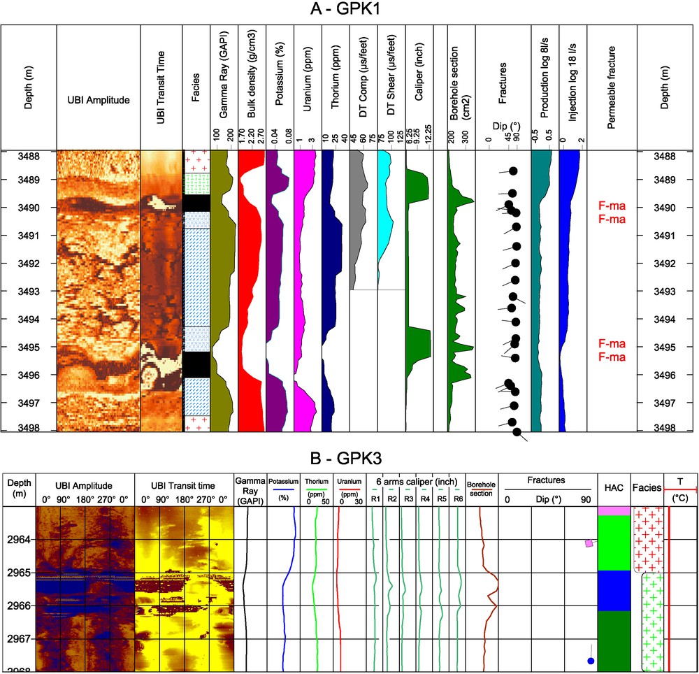
Examples of composite logs for two fracture zones in GPK1 (A) and GPK3 (B). UBI: acoustic borehole image; HAC: Hierarchical Ascendant Classification; Legend of facies: red crosses: porphyritic granite; green crosses: two-mica granite; green hachure: altered granite; blue hachure: cataclased granite; blue crosses: brecciated granite; black: quartz vein.
Exemples de logs composites pour deux zones de fractures dans GPK1 (A) et GPK3 (B). UBI : images de paroi acoustiques ; HAC : Classification Ascendante Hiérarchique ; Légende des faciès : croix rouges : granite porphyroïde ; croix vertes : granite à deux micas ; hachures vertes : granite altéré ; hachures bleues : granite cataclasé ; croix bleues : granite bréchifié ; noir : veine de quartz.
However, we cannot determine if there are some evidences of natural permeability in a given fracture by interpreting geological data only. Then, in addition, temperature and flow logs analysis was used to determine the zone of fluid lost in the boreholes (Evans, 2000; Dezayes et al., 2004).
In the framework of the Soultz geothermal project, several wells have been drilled for exploration and for the geothermal reservoir development and exploitation (Dezayes et al., 2005). In these wells, different data have been acquired, but these data are not homogeneous in terms of characterization and resolution. Thus, fracture zone characterization will be not strictly equivalent for all wells.
4 Mesoscale fractures
Many fracture data have been collected in the granite basement based on coring and especially borehole imaging (Genter et al., 2007). The analyses of these fracture data show that the main strike is consistent between the different imagery logs and the different wells (Fig. 3; (Genter, 1989; Genter et al., 2000; Dezayes et al., 2004)). In EPS1, the coring has begun at 920 m in the lower Muschelkalk. The fractures present in the Buntsandstein formation have been measured and oriented as in the granite. In this sedimentary cover, the fracture network is limited scattering around N175°E. Two conjugate and symmetrical major poles are present, as well as it is more scattered and asymmetrical in the granite. In the granite, the major direction varies from N160°E to north-south with steep dipping eastward and westward. However, the orientations of fractures observed in cores (EPS1) are rather scattered with various dipping values (Fig. 3). In these cores, some faults showing striations have been measured and the Oligocene paleostress states have been retrieved by inversion (Dezayes et al., 1995). Among the fractures in granite, based on borehole image interpretation, seven sets have been isolated by statistical method (Valley, 2007). 60% of fractures belong to two sets striking north–south and dipping to the west and to the east. This orientation corresponds to the Rhenish orientation described at graben and site scales. A subvertical set, striking NW–SE, appears also at large scale but outside of the Rhine Graben in Vosges and Black Forest massif and in the Triassic sediments. Another subvertical perpendicular set, striking NE–SW, is parallel to the Hercynian large-scale faults, like the Lalaye-Lubine-Baden-Baden fault. These four sets include 95% of all fractures found in granite (Valley, 2007). It appears clearly that the granite batholith has recorded a polyphased tectonic history. With depth, the strike of the main north–south sets remains roughly similar, however balance between the dominant dip orientation evolved (Fig. 3). In GPK3 and GPK4, between 1420 to 2700 m True Vertical Depth (TVD), the main fracture set dips to the east. In the middle part of the borehole sections, between 2700 m to about 4800 m depth, the two conjugate sets are equally represented with fracture sets dipping westward and eastward. In the bottom part of the wells, below 4800 to 5000 m depth, the westward set is dominant (Fig. 3). Studies of abutting relations and fracture size in GPK3 and GPK4 also support this repartition with depth (Valley, 2007).
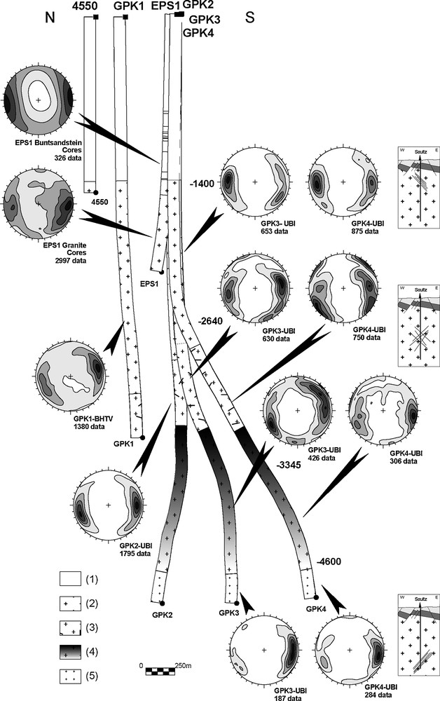
Fracture orientation in the Soultz wells based in cores and various borehole image logs. For the GPK3 and GPK4 wells, data are grouped in relation with the major petrographical sections (from Hooijkaas et al., 2006). The depths along the wells indicate the upper and the lower depth limits of the petrographical sections (in True Vertical Depth Sub Sea). Contour-density diagrams in Schmidt's projection, lower hemisphere: 10%, 30%, 50%, 70%, and 90% of the maximum frequency. Geology: (1) Sedimentary cover, (2) Standard porphyritic granite, (3) Standard granite with intense vein alteration, (4) Biotite and amphibole rich granite gradually becoming standard granite with depth, (5) Two mica granite and biotite rich granite.
Orientation des fractures dans les puits de Soultz à partir de l’analyse des carottes et des images de paroi. Pour les puits GPK3 et GPK4, les données sont regroupées par faciès pétrographique majeur (Hooijkaas et al., 2006). La profondeur le long des puits indique la limite supérieure et inférieure des sections pétrographiques (altitude à partir du niveau marin de l’IGN). Diagramme de densité en projection de Schmidt, hémisphère inférieur, courbes à 10 %, 30 %, 50 %, 70 %, 90 % de la fréquence maximale. Géologie : (1) couverture sédimentaire, (2) granite standard, (3) granite standard avec une altération filonienne intensive, (4) granite riche en amphibole et en biotite évoluant progressivement vers un granite standard. (5) granite à deux micas et granite riche en biotite.
5 Determination of fracture zones
In the six wells of the Soultz site, we considered 39 fracture zones, which indicate some potential traces of fluid flow (Table 1, Fig. 4). This list of fracture zone is probably not exhaustive and could be completed later by further data acquisition or processing.
Caractéristiques des zones de fracture déterminées dans les puits de Soultz.
| Well | Name | Depth | Level | TVDss | Dip_dir (°E) | Dip (°) | Thickness (m) |
| EPS1 | EPS1-FZ1010 | 1012 | 3 | 836.637512 | 130 | 79 | |
| EPS1 | EPS1-FZ1200 | 1198 | 1 | 1021.84821 | 247 | 74 | 30 |
| EPS1 | EPS1-FZ1640 | 1643 | 2 | 1466.48914 | 76 | 58 | 25 |
| EPS1 | EPS1-FZ2180 | 2179 | 1 | 1988.09058 | 278 | 53 | 15 |
| GPK1 | GPK1-FZ1015 | 1015 | 3 | 862.00885 | 270 | 45 | |
| GPK1 | GPK1-FZ1220 | 1220 | 1 | 1066.59717 | 247 | 74 | |
| GPK1 | GPK1-FZ1820 | 1820 | 1 | 1666.24219 | 27 | 47 | 10 |
| GPK1 | GPK1-FZ2815 | 2815 | 2 | 2657.19238 | 230 | 70 | 8 |
| GPK1 | GPK1-FZ3220 | 3223 | 3 | 3064.05273 | 60 | 75 | 15 |
| GPK1 | GPK1-FZ3490 | 3492 | 2 | 3332.64502 | 257 | 63 | 8 |
| GPK2 | GPK2-FZ2120 | 2123 | 1 | 1953.37292 | 65 | 70 | 15 |
| GPK2 | GPK2-FZ3240 | 3242 | 3 | 3069.90625 | 82 | 69 | 0.5 |
| GPK2 | GPK2-FZ3350 | 3347 | 3 | 3174.62988 | 231 | 84 | 3 |
| GPK2 | GPK2-FZ3515 | 3514 | 3 | 3341.70801 | 313 | 56 | 12 |
| GPK2 | GPK2-FZ3900 | 3900 | 2 | 3726.61133 | 234 | 64 | |
| GPK2 | GPK2-FZ4760 | 4760 | 2 | 4544.82227 | 250 | 65 | No |
| GPK2 | GPK2-FZ4890 | 4890 | 3 | 4668.3252 | 250 | 65 | Image |
| GPK2 | GPK2-FZ5060 | 5060 | 2 | 4831.29248 | 250 | 65 | Logs |
| GPK3 | GPK3-FZ1580 | 1579 | 3 | 1410.36487 | 69 | 78 | 8 |
| GPK3 | GPK3-FZ1640 | 1637 | 3 | 1468.78821 | 46 | 68 | 8 |
| GPK3 | GPK3-FZ1820 | 1820 | 3 | 1651.01147 | 46 | 64 | 3–4 |
| GPK3 | GPK3-FZ2040 | 2042 | 3 | 1873.30823 | 72 | 65 | 8 |
| GPK3 | GPK3-FZ2045 | 2046 | 3 | 1876.76367 | 243 | 69 | 1 |
| GPK3 | GPK3-FZ2090 | 2092 | 3 | 1923.16223 | 91 | 76 | 6 |
| GPK3 | GPK3-FZ2970 | 2970 | 2 | 2798.43579 | 77 | 82 | 9 |
| GPK3 | GPK3-FZ3270 | 3271 | 2 | 3092.95361 | 345 | 85 | 15 |
| GPK3 | GPK3-FZ4090 | 4089 | 3 | 3856.2417 | 253 | 62 | 6 |
| GPK3 | GPK3-FZ4770 | 4775 | 1 | 4538.90137 | 234 | 64 | 15 |
| GPK4 | GPK4-FZ1720 | 1723 | 3 | 1554.30212 | 216 | 69 | 2 |
| GPK4 | GPK4-FZ1800 | 1801 | 3 | 1632.22925 | 26 | 80 | 12 |
| GPK4 | GPK4-FZ2820 | 2817 | 3 | 2762.20264 | 242 | 86 | 9 |
| GPK4 | GPK4-FZ3940 | 3940 | 3 | 3603.97852 | 250 | 68 | 60 |
| GPK4 | GPK4-FZ4360 | 4361 | 2 | 3963.29565 | 280 | 77 | 4 |
| GPK4 | GPK4-FZ4620 | 4620 | 3 | 4195.97852 | 285 | 78 | 40 |
| GPK4 | GPK4-FZ4710 | 4712 | 2 | 4279.59717 | 212 | 50 | 1 |
| GPK4 | GPK4-FZ4970 | 4973 | 3 | 4530.36914 | 276 | 81 | 2 |
| GPK4 | GPK4-FZ5050 | 5012 | 3 | 4568.51904 | 257 | 85 | 15 |
| GPK4 | GPK4-FZ5100 | 5100 | 3 | 4655.44922 | 255 | 69 | 10 |
| 4550 | 4550-FZ1265 | 1265 | 1 | 1107.95679 | 260 | 75 | 3 |
Orientation of fracture zones in each Soultz well. Bold lines and black dots: cyclographic traces and poles of fracture zones of level 1; grey lines and grey dots: cyclographic traces and poles of fracture zones of level 2 (dotted grey line: supposed orientation); dotted line and white dot: cyclographic trace and pole of fracture zones of level 3 (Schmidt's projection, lower hemisphere).
Orientation des zones de fracture dans les différents puits de Soultz. Lignes épaisses noires et points noirs : traces cyclographiques et pôles des zones de fracture de niveau 1 ; lignes grises et points gris : traces cyclographiques et pôles des zones de fracture de niveau 2 (ligne en pointillé gris : orientation hypothétique) ; lignes pointillées noires et points blancs : traces cyclographiques et pôles des zones de fracture de niveau 3.
The fracture zones have been classified within three levels in attempting to reflect their relative scale and importance as fluid flow paths. The first level (1 in the Table 1) concerns the major fracture zones, which have been detected during drilling operations with important mud losses and then are permeable prior to any stimulation operations. The fracture zones of the second level (2 in the Table 1) show flow indication higher than 20% of water losses during stimulation and/or are characterized by the other available geological data to include at least one thick fracture accompanied with a significant halo of hydrothermal alteration. The last level (3 in the Table 1) includes the fracture zones having a poorly developed alteration halo and a flow level below 20% of water losses during stimulation. This level indicates fracture zones of smaller size than those of the two other levels previously defined.
In the three wells EPS1, GPK1 and 4550, a major fault zone intersects the Buntsandstein sediment at around 1200 m (Table 1). This zone has been cored by the EPS1 well and where it forms a large structure containing 3 subzones and presenting fractures with quartz, galena and barite fillings. In the GPK1 and 4550 wells, total drilling mud losses have occurred when drilling through this zone (Herbrich, 1988; Villeneuve and Weber, 1991). In the 4550 well, a BHTV log is available and allows the characterization of the fracture zone. This presents a series of open steeply dipping fractures. However, the orientation value is not very precise due to the rather bad quality of the image log.
In the GPK1 well, another natural brine inflow occurred during the drilling at the depth of the large fracture zone at 1820 m MD (Table 1, (Herbrich, 1988)). At this depth, a very high helium content anomaly was recorded (Vuataz et al., 1990) and other drilling anomalies were reported. This fracture zone contains geodic quartz veins, visible in a core taken at this depth as well as illite (Genter, 1989).
Also, in the upper part of the granite, in GPK2 well, a fracture zone provoking total drilling mud losses has been intersected and no cuttings have been collected below (Genter et al., 1995). The fracture zone at 2120 m MD shows a high altered zone with several open fractures (Table 1). The hydraulic testing of an open hole interval including this fracture zone showed that 95% of the flow rate was absorbed by this zone (Jung et al., 1995). This zone is also believed to be responsible for a large-scale stress perturbation, as highlighted by the analysis of borehole failure (Valley and Evans, 2007).
At greater depths, there are no major fracture zones except at the bottom of the GPK3 well, within the open hole, there is a major fracture zone located around 4770 m MD (Table 1). This zone includes several individual fractures with a cumulative apparent thickness of around 15 m along the well. The K content increases in the hanging wall of the zone and decrease in the center part indicating a high alteration halo. The flow rate shows a 70% outflow matching this zone (Dezayes et al., 2004). Analysis of borehole failure showed that this zone is inducing a major stress perturbation (Valley, 2007). This is the major flow pathway in the geothermal reservoir at lower depth. GPK4 is the only well where there is no level 1 fracture zone (Table 1). The description of the fracture zones is detailed in Dezayes and Genter (2008).
6 Fracture zones characteristics
The orientation of these fracture zones is based on borehole images as described above (Fig. 4). Most of orientations of fracture zones have been determined according to the assumptions cited above. However, some of them are more difficult to estimate and are detailed in the following text. The orientation of the fracture zone in GPK3 at 3270 m, which appears east–west striking (Fig. 4D, Table 1), is very imprecise. The image log quality is locally poor and no correct measure has been done. Moreover, in GPK2, some orientation of fracture zones could not been measured at all. This well was drilled in two times, in 1995 and 1999, and some problems occurred at 3900 m, where the first drilling stopped. At that depth, caliper log indicates the development of a large cave (Genter et al., 1999). Some altered cuttings coming from this zone have been recovered at the end of the drilling operation in 1995. After the deepening in 1999, as this large cave occurs in a significantly deviated part of the well, the UBI tool stuck and no image log has been run below that depth. Later, the borehole has been cased and now, the presence of a casing restriction is suspected due a partial casing collapse induced by the fracture zone. Using 3D visualization (Sausse et al., 2010), we suspect that this fracture zone is the same that the one cross-cutting the bottom of GPK3 well (GPK3-FZ4770 in Table 1). Thus, we assumed that this zone has the same orientation (Table 1). However, due to this GPK2 borehole wall restriction at 3900 m, no logging tools could be run below this depth now. Below 3900 m, only temperature and flow logs are available. Then, we have located three zones with outflow which match with altered zones based on cutting observation. These zones occur at 4760 m with 20% of flow, 4890 m with 17% of flow and 50% of flow below 4960 m which could correspond to a fracture zone occurring at 5060 m, based on cutting observation. As there are no oriented image logs in this section, we have assumed a generic orientation, which is realistic but not proven, N250°E–65° (N160°E–65°W), the dominant orientation of fractures in the deeper part of the Soultz granite (Fig. 4C).
At Soultz, fractures are mainly detected from acoustic borehole images. Thus, apart the location, the dip, and the dip direction of a given fracture, we cannot get any information about the fracture type (extension or shear), the nature of the hydrothermal filling and the fracture length. Moreover, it is rather difficult to derive the fracture thickness of an individual fracture from a borehole images, mainly because the physical significance of a fracture signature. From continuous core analysis done on the referential exploration well (EPS1), more than 3000 of fractures and several fracture zones have been fully characterized (Genter et al., 2007). The distribution of core fracture thickness is governed by a power law and ranges over several decades from 0.1 to 250 mm. The smallest fractures (thickness between 0.1 and 10 mm) correspond mainly to extensional fractures (Mode I) associated to shear fractures, whereas the largest correspond to shear fractures only (Mode II) (Genter et al., 2007). Even with the fine resolution scale core data, the fracture length cannot be estimated and calibration has to be done from outcrops (Gudmundsson et al., 2002).
The fracture zones considered in this paper have been interpreted as composed of shear fractures highly clustered. This results in a fracture zone organization composed of a core zone, a damage zone and hydrothermally altered granite, following the conceptual scheme for fault-related fluid flow (Genter et al., 2002; Genter et al., 2007; Caine et al., 1996; Gudmundsson et al., 2001). Some altered cataclastic shear zones showed a low natural permeability in channels characterized by the occurrence of brines (100 g/L) and were defined as Hydrothermally Altered and Fractured Zones (HAFZ) indicating both high fracture density and strong hydrothermal alteration (Genter, 1989; Genter et al., 2002). Some of those HAFZ were detected during drilling operation and showed a very low initial permeability which has been subsequently improved by hydraulic/chemical stimulations (Evans et al., 2005; Dorbath et al., 2009). Natural fluid circulation in the fractures resulted in both a strong dissolution of the primary minerals such as biotite, plagioclase, and a significant deposition of some altered minerals such as clay minerals (illite), calcite and secondary quartz. Thus, natural permeability which is mainly related to fracture zones, shows a porous damage zone and a fractured core zone (Genter et al., 2002; Evans et al., 2005). In other extensional context, fault zone architecture and permeability structure show a nearly impermeable fault core associated with a rather permeable highly fractured damage zone (Micarelli et al., 2003).
As this granite is not outcropping on surface, fracture zones characteristics have been compared with relevant hard rock analogues occurring in a normal faulting context (Bruhn et al., 1994). For both, fracturing and hydrothermal alteration are intimately linked to the natural permeability conditions. Based on borehole image log data, fracture zone thickness ranges between 0.5 and 60 m with an average value of 12 m (Table 1). Fracture thickness data estimated in volcanic paleogeothermal fields and controlled by large-scale strike-slip fault mechanism show core thickness up to several tens of meters and damage zone thickness up to several hundred meters (Gudmundsson et al., 2001). At Soultz, fracture zone thickness is five to ten times smaller than previously. That could be interpreted in terms of intermediate scale normal faults with moderate offset. In case of an active graben context, the fracture zone thickness data show the same order of magnitude than Soultz (Micarelli et al., 2003).
7 Spatial organization of the fracture zones
Most of the fracture zones characterized in the framework of this study (Table 1) can be attributed to three main concentrations or clusters of fractures zones at about 1800–2000 m, 3000–3400 m and around 4500–5000 m TVD (Fig. 5). In that regard, the borehole GPK4 is somehow untypical, presenting less clearly clustered, steeply dipping fracture (Fig. 5), while in the other wells, fracture zones more consistently correspond to these three fracture zone concentrations. This result was already mentioned previously in the upper part of the granite body, before the deepening of GPK2 and the drilling of GPK3 and GPK4 (Genter et al., 1995; Genter and Castaing, 1997). These three clusters of fracture zones are considered to reflect major fault, equivalent to the fault detected in the sedimentary cover based on seismic reflection (Genter and Castaing, 1997). If we assume that these faults are steeply dipping structures with values higher than 60°, the raw spacing between to consecutive clusters of fracture zones is around 500 m, equivalent to the fault spacing in the sedimentary cover (Valley and Evans, 2007).
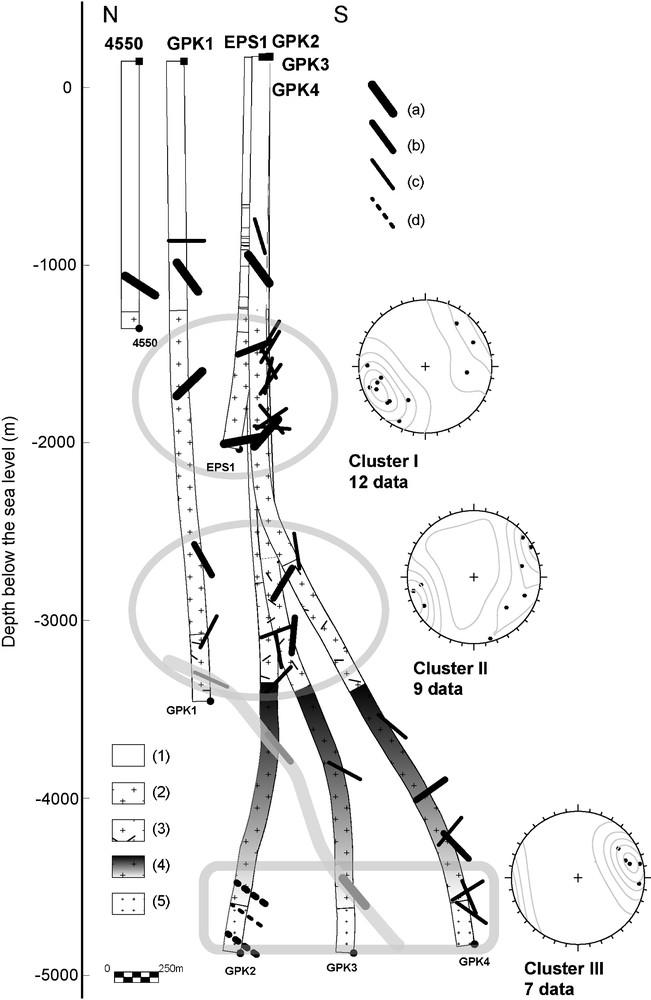
North–south cross-section through the Soultz wells showing all fracture zones determined in this study. Sticks represent the apparent dip of fracture zones through the north–south cross-section. (a) fracture zones level 1, (b) fracture zones level 2, (c) fracture zones level 3, (d) supposed orientation. Pole and contouring diagram of the fracture zones in each cluster (Schmidt's projection, lower hemisphere, contouring diagram: 10%, 30%, 50%, 70%, and 90% of the maximum frequency). Geology: (1) Sedimentary cover, (2) Standard porphyritic granite, (3) Standard granite with intense vein alteration, (4) Biotite and amphibole rich granite gradually becoming standard granite with depth, (5) Two mica granite and biotite rich granite.
Coupe nord–sud à travers les puits de Soultz montrant les zones de fracture déterminées dans cette étude. Les bâtonnets représentent l’inclinaison apparente des zones de fracture le long de la coupe nord–sud. (a) Zones de fracture de niveau 1, (b) zones de fracture de niveau 2, (c) zones de fracture de niveau 3, (d) orientation hypothétique. Pôles et diagrammes de densité des zones de fracture pour chaque cluster (projection de Schmidt, hémisphère inférieur, courbes à %, 30 %, 50 %, 70 %, 90 % de la fréquence maximale). Géologie : (1) couverture sédimentaire, (2) granite standard, (3) granite standard avec une altération de veine intensive, (4) granite riche en amphibole et en biotite redevenant progressivement un granite standard. (5) granite à deux micas et granite riche en biotite.
The upper cluster at 1800–2000 m depth (Cluster I in Fig. 5) is located in the unaltered porphyritic granite. This cluster includes major fracture zones qualified as level 1 with permeable zones. The cluster II does not include major level 1 faults. It is located within the fractured and altered granite zone (Fig. 5). This granite facies is characterized by high pervasive alteration related to numerous small-scale fractures present in this zone (Hooijkaas et al., 2006). This facies contains a high proportion of clay and hydrothermal minerals. Possibly, the high fracturing of this facies leads to a generally weaker rock mass where the strain is distributed in small increments over a dense network of smaller fractures, instead of being concentrated by a few major faults. This location corresponds to the upper reservoir stimulated in the first phase of the project in 1997 (Baumgärtner et al., 1996). In this reservoir, a four months circulation test including tracer injection has been performed with success. Then, it appears that there is a good fluid connection in this reservoir between GPK1 and GPK2. The lower cluster (Cluster III in the Fig. 5) is close to the interface between the 2 granite units at 4700 m depth TVD. The deep facies is characterized by massive granite characterized by a low pervasive alteration degree. The cluster III contains major fracture zone as the GPK3-FZ4770. Thus, it appears that the deformation in this facies tends to be localized along major isolated fracture zones. This last cluster is located in the lower reservoir, which has been stimulated previously, and is currently a part of the deep geothermal loop under testing for the electrical production test. Conceptually, this reservoir appears to behave as a fractured reservoir embedded in a low permeable matrix.
Based on this characterization of fracture zones at borehole scale, these major planes have been compared with other fracture information derived from other detection methods in order to build a 3D model (Sausse et al., 2010). These other methods are microseismicity data created within the reservoir during the stimulations of GPK2, GPK3 and GPK4 (Dorbath et al., 2009) and a Vertical Seismic Profiling (VSP) investigation (Place et al., 2010). Some of the fracture zones observed at the well scale match with microseismicity or VSP results. They correspond to fracture zones qualified by level 1 or 2 such as GPK1-FZ3490, GPK2-FZ3900 and GPK3-FZ4770, which match with microseismicity and VSP analysis. Moreover, the dip orientations of the fracture zones are very close and seem to define a large-scale fault intersecting the Soultz basement (Fig. 5). This orientation of the major fracture zone is about N230°E–70° (N140°E–70°W).
In GPK1, two fracture zones at 1820 and 2860 m appear to match with the VSP analysis (Place et al., 2010; Sausse et al., 2010).
In the lower part of the reservoir, two smaller fracture zones in GPK4 match geometrically with the microseismicity analysis at 4620 and 4970 m (Dorbath et al., 2009). These fracture zones are N10°E striking, steeply dipping to the west (Fig. 5).
8 Discussion
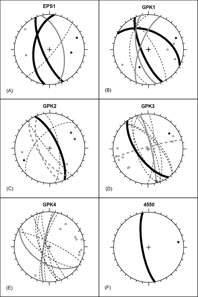
The average strike direction of fracture zones characterized in the Buntsandstein sandstones and the granite is N165°E ± 10° and N160°E ± 15° respectively (Fig. 6A1–6B1). A secondary fracture zone set in the Buntsandstein is N40°E striking. In the granite, two secondary sets are present with a N20°E ± 10° and N130°E ± 10° direction. The average dip is higher than 60° (Fig. 6 A1–6B1). These orientations are consistent through the granite and the Buntsandstein sedimentary cover. In both cases, fracture zones dominantly dip to the west. The orientation of mesoscale fractures measured in the Buntsandstein in the EPS1 cores (Fig. 6A2) and in the granite on the borehole images shows a N0°E ± 20° and N175°E ± 30° direction respectively (Fig. 6B2). In the Buntsandstein, dips are equally-balanced between the west and the east, whereas in the granite, more fractures dip to the west. Then, it appears that there is no mechanical decoupling between this both geological brittle units.
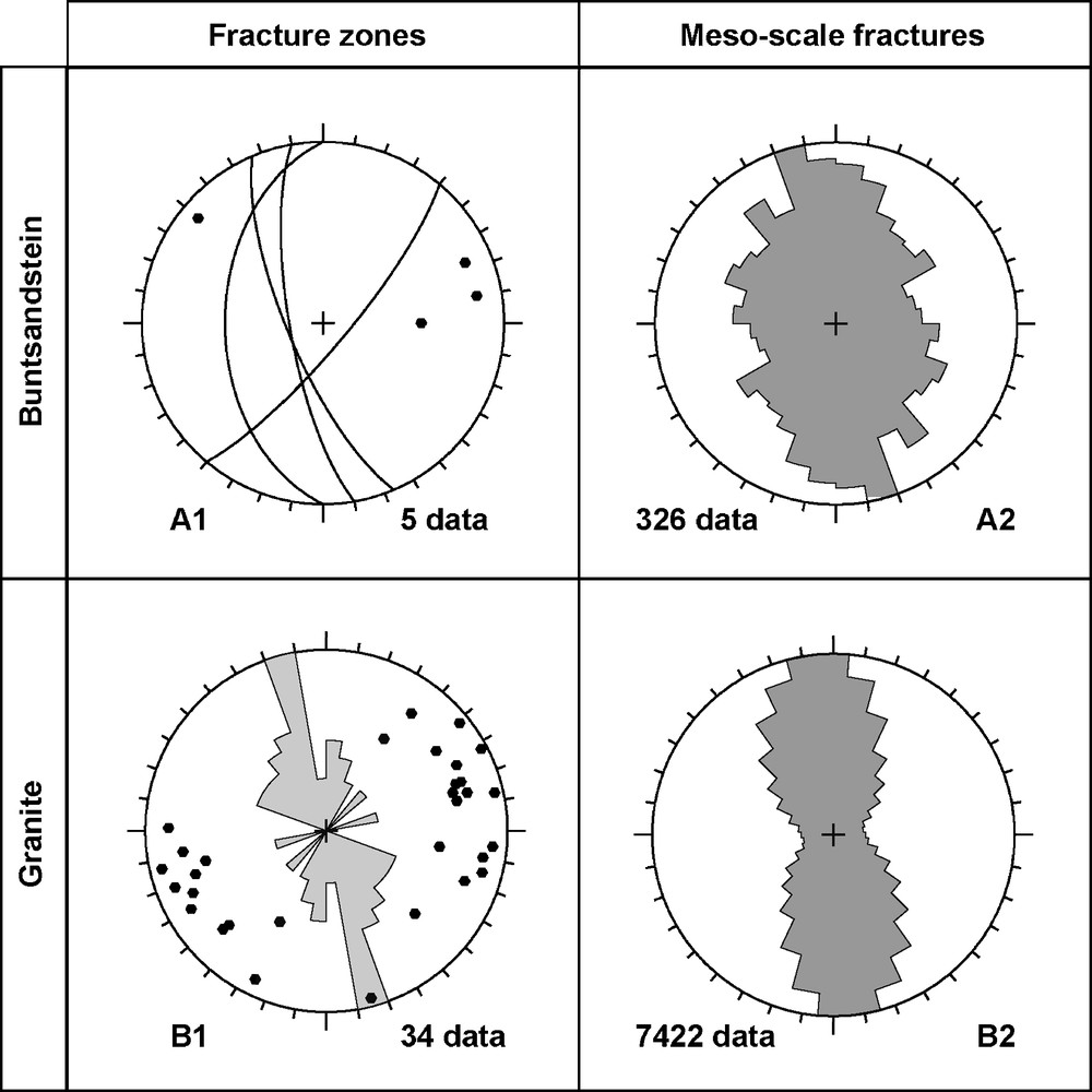
Orientation of fractures zones and mesoscale fractures in the Buntsandstein sediments (A) and in the granite (B). (A1) Traces and poles of fracture zones in the Buntsandstein; (A2) strike rose diagram (10° class angle) of mesoscale fractures measured in EPS1 Buntsandstein cores; (B1) poles and strike rose diagram (10° class angle) of fracture zone in the granite; (B2) strike rose diagram (10° class angle) of mesoscale fractures measured on borehole images in the granite of all wells.
Orientation des zones de fractures et des mésofractures dans les sédiments du Buntsandstein (A) et dans le granite (B). (A1) Traces et pôles des zones de fracture dans le Buntsandstein ; (A2) rosace de direction (classes de 10°) des mésofractures mesurées sur les carottes de Buntsandstein du forage EPS1 ; (B1) pôles et rosace de direction (classes de 10°) des zones de fractures dans le granite ; (B2) rosace de direction (classes de 10°) des mésofractures mesurées sur les images de paroi de tous les forages dans le granite.
If we compare the orientation of fracture zones with the mesoscale fractures, we can observe a clockwise rotation of 10–15° for both fractures in the Buntsandstein and in the granite (Fig. 6). However, in all the cases, the west dipping direction is dominating.
In previous studies, these fracture zone concentrations were interpreted as the occurrence of large-scale normal fault zones related to the Rhine Graben tectonics. However, the direction of the fracture zone, as the direction of mesoscale fractures, is slightly different than the major fault orientation observed in the sedimentary cover, which have a Rhenish direction of N20°E and which corresponds to the graben opening at Oligocene. The granite contains numerous fracture orientations related to Hercynian and Alpine tectonics. It seems that the N160°E is an inherited direction, which has been reactivated during the graben tectonic. Thus, the main fracture zone orientation is rather different than those newly created in the sedimentary cover during Cenozoic. A remaining question is: what is the relationship between the major faults in the sedimentary cover and the fracture zone clusters? Ongoing work aims to tackle this question by developing a 3D large-scale geometrical model based on an exhaustive geological database (Castera et al., 2008; Place et al., 2010; Sausse et al., 2010).
Moreover, the average direction of the fracture zones is rather consistent with the present-day stress field with σH N169°E ± 14° (Klee and Rummel, 1993; Valley et al., 2007). Some fracture zones which show flow anomalies or shearing indications appear as small fractures on the borehole image logs. This seems to indicate that critically oriented fractures relatively to the stress state orientation could shear during hydraulic stimulation (Evans, 2005).
9 Conclusions
Characterization of the main fracture zones likely to bear fluid flow prior or after stimulations was achieved along the Soultz wells based on direct (cores, cuttings) and indirect (borehole images, geophysical logs, flow logs, temperature logs) methods. We have compiled and matched these different data to highlight a set of 39 fracture zones intersecting the five boreholes of the geothermal site as well as a peripheral well. This list is not exhaustive and could be completed by further data acquisition or processing.
Knowledge and in situ characterization of fracture zone along the well have to be taken into account for a better understanding of the life time of the geothermal reservoir during early stages of hydraulic or chemical stimulations followed by long-term hydraulic circulations. Due to such hydraulic tests, different thermo-hydromechanical and chemical processes occur at depth in the reservoir and could modify fluid pathways. In the vicinity of the reinjection well GPK3, dominating mechanisms will be a general cooling of the fractured rock mass associated with forced fluid flow provoking thermomechanical stresses mainly. Temperature reduction could also generate some chemical effects inducing mineral dissolution or precipitation and thus strongly modify the fluid pathway during circulation. Close to the production wells GPK2 and GPK4, the pumping due to submersible pumps could also induce some hydromechanical processes in the fractured rock mass. All these complex thermo-hydromechanical coupling will interact with the major fracture zone system and have to be seriously investigated by modeling for the reservoir life time (temperature drawdown, microseismicity risk, reservoir clogging). The fracture zone dataset studied in this paper could be used for modeling the thermohydraulic mechanical behavior of the deep geothermal granite reservoir submitted to prehydraulic or chemical stimulations followed by long-term hydraulic circulations.
Acknowledgements
This work has been carried under financial support of ADEME, Europe and BRGM (EGS3D project). B. Valley contribution was supported by the Swiss State Secretariat for Education and Research, and was performed as a contribution to the European Union's FP6 project “Soultz EGS Pilot Plant” funded by ADEME, BMU, EC and EEIG “Exploitation Minière de la Chaleur”. EHDRA working group 6 and 7 teams are kindly thankful for their contributions and for their fruitful discussion. The authors are very grateful to A. Gudmundsson and an anonymous reviewer for fruitful comments and manuscript improvements.