

1 Introduction
The Kawai-type multianvil apparatus (KMA), or 6–8 type multianvil apparatus, uses six first-stage anvils made of hardened steel and eight second-stage cubic anvils of tungsten carbide (WC), operated in a large volume press (Kawai and Endo, 1970). KMA provides well-controlled pressure and temperature in larger sample volumes as compared to those available in a laser-heated diamond anvil cell. However, achievable pressures in KMA have been limited to about 30 GPa using conventional WC anvils (e.g., Ito, 2007), except for those of some recent studies using harder WC anvils, which demonstrated that pressures as high as 50–60 GPa could be produced in KMA (Ishii et al., 2017; Kunimoto et al., 2016).
Sintered bodies of diamond powders with some metal binders have been used as “second-generation” anvils for KMA, because such sintered-diamond (SD) anvils are much harder than conventional WC anvils. The edge length of commercially available SD anvil cubes was limited to 10 mm in the initial stage of the development of the KMA technology using SD anvils (e.g., Funamori et al., 1996; Kondo et al., 1993; Ohtani et al., 1989), and the DIA-type apparatus was needed to pressurize such small anvils for precise alignment of the first-stage anvils. Achievable pressures with the SD anvils, however, were limited to ∼30 GPa, partly because of the limited anvil size and also due to the limitation in applicable press load by the multianvil apparatus (e.g., MAX-80 at KEK) at the synchrotron facility till the late 1990s, when a larger multianvil press operated in a 15-MN press (SPEED-1500) was installed at SPring-8 (Utsumi et al., 2003).
Accordingly, larger SD anvils with an edge length of 14 mm were introduced, on which about press loads twice as high as those for the 10-mm anvils can be safely applied. This led to an expansion of pressure to about 40 GPa in KMA (e.g., Irifune et al., 2002; Kubo et al., 2003), but the generation of higher pressures remained difficult because of the frequent occurrence of blow-out. This is mainly due to uneven compression of the second-stage SD anvils, as the vertical compression by the upper and lower first-stage anvils tends to become stronger than the horizontal compression by side anvils with increasing press load, because of elastic bending of the upper and lower guide blocks. This shortcoming was later improved by introducing a newly designed apparatus (SPEED-MkII) at SPring-8 (Katsura et al., 2004), followed by replacement of the guide block system of SPEED-MkII with a more sophisticated system (MADONNA-type system; Irifune, 2010) to realize further even compression of the second-stage anvils.
Parallel to these developments in the guide-block system, efforts have been made to improve the materials and designs of the pressure medium/gasket suitable for the generation of higher pressures using SD anvils (e.g., Tange et al., 2008a, b). As a result, the maximum achievable pressure in KMA has been increasing year by year in the last decade (Ito et al., 2005; Tange et al., 2008a, b; Yamazaki et al., 2006, 2014), and a recent study reported the generation of pressures until ∼120 GPa (Yamazaki et al., this issue), which is once predicted to be the maximum pressure achievable with SD anvils (Ito, 2007). However, significant elastic deformation of the SD anvils is noted under such very high pressure, which hinders effective in situ X-ray observations of the sample because of the extremely small anvil gap due to elastic swelling of SD anvils behind the decompressed regions near the anvil top (Yamazaki et al., this issue).
We reported the synthesis of well-sintered nano-polycrystalline diamond (NPD) directly converted from various carbon sources at pressures above ∼12 GPa and at temperatures exceeding 2300 K (Irifune et al., 2003; Isobe et al., 2010), which was found to have extremely high hardness, with a Knoop hardness (Hk) of 130–145 GPa, far higher than that of commercially available SD (generally, Hk = 50–70 GPa). Subsequent development of techniques in synthesizing NPDs with larger dimensions and higher quality has led to those samples with high transparency and dimensions up to 1 cm in both diameter and length (Irifune et al., 2014). We have tested NPD as anvils for higher pressure generation and for newer experimental studies using KMA.
2 Experimental
2.1 NPD anvil
NPD was synthesized from pure graphite starting material with a rod shape, having a diameter of 10.5 mm and a length of 9.0 mm, at 15 GPa and 2600 K for 20 min, using a large-volume multianvil apparatus operated in a 6000-ton press (BOTCHAN-6000; Irifune, 2010; Irifune et al., 2014) at the Geodynamics Research Center, Ehime University, Japan. The temperature was then decreased to about 1100 K and the pressure was released slowly over several hours at high temperature to maintain a quasi-hydrostatic pressure around the sample so that the occurrence of cracks is avoided.
Thus, the synthesized NPD rod had dimensions of ∼9 mm in diameter and ∼8 mm in length, and was highly transparent and yellowish brown in color without any visible cracks, which should have grain sizes of typically 20–50 nm (Dubrovinskaia et al., 2016; Ohfuji et al., 2012). Note that the grain size distributions change depending on the used carbon source (Ohfuji et al., 2012), and that the grain sizes of the present NPD are slightly larger than those reported in our first report on the synthesis of NPD (10–20 nm; Irifune et al., 2003). Nevertheless, the Knoop hardness of the present NPD is in the range 130–140 GPa, which is similar to that of the earlier study.
The NPD rods were cut by a pulsed laser (Okuchi et al., 2009) to form cubes with an edge length of 6.00(1) mm. The cubes were heated at 773 K for 10 min to remove carbon debris formed upon laser cutting, but their surfaces were left unpolished after cutting. The surface roughness (Ra) of the cubes measured with a laser microscope (Lasertec, Optelics Hybrid L3) was Ra = 0.53 μm, which is similar to those of the commercially available SD anvils (Sumitomo Electric Industries Co. Ltd, WD700) used in run M2020 (Ra = 0.44 μm) and the SD anvils with 6 mm edge length used in run M1185 (Ra = 0.68 μm). No visible damages inside the NPD cubes were noted under the optical microscope after laser cutting and heat treatment, and the cubes remained transparent, as shown in Fig. 1.
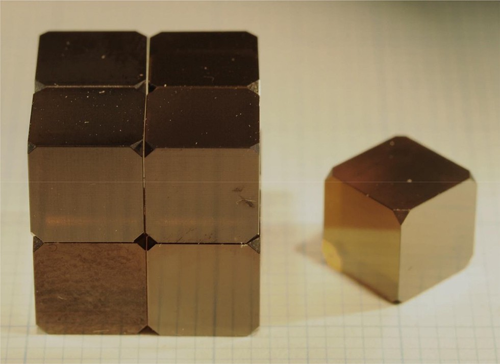
A photograph of the third-stage NPD anvils with an edge length of 6 mm and an anvil truncation (TEL) of 1.0 mm.
We also prepared SD cubes (WD700) with an edge length identical to that of the above NPD cubes (6 mm) for comparisons in pressure generation and X-ray transparency. The SD cubes conventionally used in KMA experiments (i.e. 14 mm edge length) were also used for similar comparisons in the later stage of the present study, simply due to a lack of the smaller SD cubes as we lost most of them after the blow-out.
2.2 Anvil configuration and cell assemblage
We adopted the 6–6–8 configuration for operation of the small NPD cubes in a multianvil press (SPEED-MkII with the MADONNA-type guide block system) at BL04B1, SPring-8, based on the 6–6 assembly (Nishiyama et al., 2008). The first-stage six anvils are made of WC with a square anvil top of 27 mm edge length, which are normally adopted for the experiments using the second-stage SD anvils with the standard size of 14 mm in edge length. As our NPD cubes are far smaller than these SD anvils, we need to put six hard “spacers” (= second-stage anvils) between the first-stage WC anvils and the eight NPD anvils (= third-stage anvils), as illustrated in Fig. 2a.
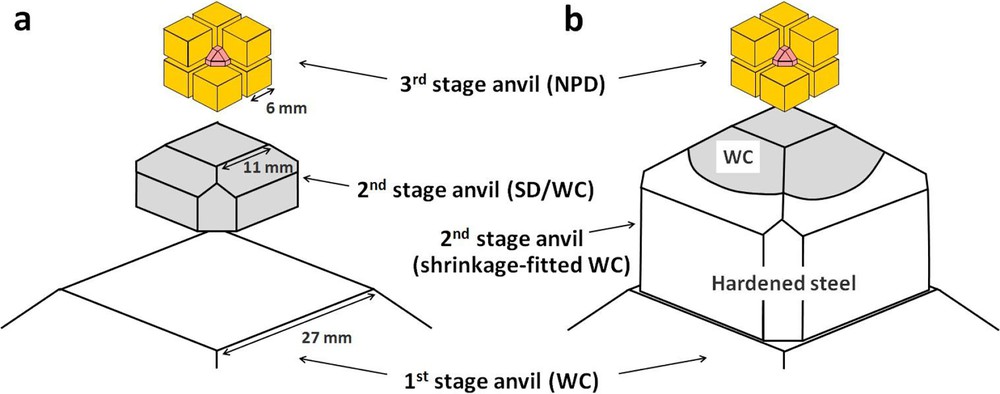
Schematic illustrations of anvil assemblies for the 6–6–8 compression. The second-stage anvils with a truncated pyramid shape made of WC or SD were used in the first series of the present experiments (a), while they were replaced by those of WC shrinkage fitted to hardened steel (b) in the second series run.
We tested two types of truncated square pyramid made of WC (Fujilloy TF06) and SD (WD700) with edge lengths of 11 mm and 18 mm for the top and bottom square surfaces, respectively, as the second-stage anvils (Fig. 2a). We also tested WC shrinkage fitted to a hardened steel frame as the second-stage anvils (Fig. 2b). We assumed typical compressional strengths of 5 GPa and 7 GPa for WC and SD used as second-stage anvils, respectively, which suggests that press loads of up to about 1.8 MN and 2.5 MN can be applied to these second-stage anvils, respectively. However, as we noted that both WC and SD second-stage anvils broke into pieces upon blow-out at press loads of ∼1.1 MN and ∼1.4 MN, respectively, in the first series of the pressure generation tests, the shrinkage fitted WC was adopted in a later experiment to enhance the compression strength of WC.
As for the gasket and pressure medium of the cell assembly for NPD anvils with a truncation size of 1.0 mm, we basically followed the designs, materials, and dimensions successfully used in our earlier experiments using SD anvils of the standard size; the gasket was made of hardened pyrophyllite fired at 973 K, while the pressure medium was an octahedron of semi-sintered alumina (Tange et al., 2008a, b). A rolled foil of Au was filled in a hole 0.5 mm in diameter in the pressure medium, which was used as the pressure reference material.
The assembled third-stage NPD anvils and the pressure medium/gasket were inserted into a box made of thin (0.12 mm) mica sheets, which was covered with six second-stage anvils, guided by a frame made of steel or duralumin (Fig. 3a). The 6–8 assemblage was placed in the middle of the six first-stage WC anvils (Fig. 3b), and compressed in the DIA-type apparatus.
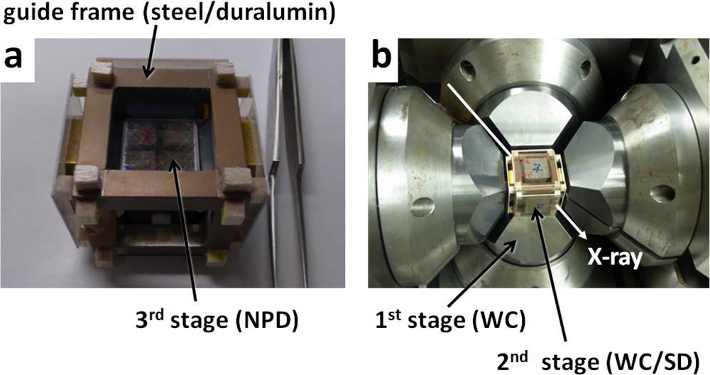
Photographs showing the anvil assemblies. The third-stage NPD anvils assembled in a mica box are placed in the guide frame made of steel or duralumin (a), where the second-stage anvils of WC or SD are inserted. The 6–8 assembly is placed in the middle space surrounded by the first-stage WC anvils and compressed in a DIA-type press (SPEED-MkII) at SPring-8 (b).
2.3 Experimental procedure
In situ X-ray diffraction measurements and imaging of the sample at 300 K were performed upon compression of the 6–6–8 system in the SPEED-MkII. The incident white X-ray beam at BL04B1 was cut by a slit to form a square cross section ∼50 μm in width and ∼100 μm in vertical length, which was directed toward the sample through the pyrophyllite gasket and the alumina pressure medium. The diffracted X-ray at 2Θ = 6 degrees was detected by a Ge solid-state detector, while the direct beam was captured by a GAGG scintillator with a CMOS camera for imaging the sample.
The X-ray image of the sample was monitored during compression with an average rate of about 0.01 MN per minute, and the diffraction measurement was made at every 0.05–0.25 MN for 120–300 s. The pressure was evaluated using the observed unit-cell volume of the Au sample, based on an equation of state (Tsuchiya, 2003). As most runs were terminated by blow-outs accompanied by substantial pressure drops, the press load was decreased quickly without taking the X-ray data upon releasing pressure.
The experimental set-up and the results of the runs are summarized in Tables 1 and 2. We made two series of experiments in the present study: three runs in the first series and two runs in the second series, with slight changes in the cell assembly (Table 1). First two runs were made using SD (run M1185) and NPD (run M1241) third-stage anvils with an edge length of 6 mm and compressed by the 6–6–8 system with WC anvils as the second-stage anvils (Fig. 2a). The pyrophyllite gaskets had a thickness of 1.4 mm and a height of 0.8 mm. The identical cell assemblage was used in the third run using NPD as the third-stage anvils (run M1265). In the third run, the second-stage WC anvils were replaced by those made of SD, as blow-outs occurred at relatively low press loads of ∼1.1 MN in the earlier two runs with the second-stage anvils made of WC.
Anvil material, gasket size, and achieved maximum load/pressure.
| Run No. | Anvil | Gasket | Loadmax | Pressmax | ||
| 2nd | 3rd | Thickness (mm) | Height (mm) | (MN) | (GPa) | |
| [First series] | ||||||
| M1185 | WC | SD | 1.4 | 0.8 | 1.0 | 33 |
| M1241 | WC | NPD | 1.4 | 0.8 | 1.0 | 39.5 |
| M1265 | SD | NPD | 1.4 | 0.8 | 1.3 | 48.4 |
| [Second series] | ||||||
| M2015 | WC* | NPD | 1.6 | 0.5 | 3.4 | 87.9 |
| M2020 | – | SD** | 1.6 | 0.5 | 3.5*** | 56.0 |
Applied loads and produced pressures for individual runs.
| Load (MN) | Pressure (GPa) | ||||
| M1185 | M1241 | M1265 | M2015 | M2020 | |
| 0.05 | - | - | - | 2.3 | 3.0 |
| 0.1 | - | - | 5.6 | 5.1 | 6.7 |
| 0.2 | - | - | 11.3 | 10.5 | 10.6 |
| 0.25 | 11.2 | 13.2 | 13.7 | - | - |
| 0.3 | - | - | 16.2 | 15.6 | 14.5 |
| 0.4 | - | - | 20.6 | 20.6 | 18.8 |
| 0.5 | 20.6 | 22.1 | 24.2 | 25.3 | 21.7 |
| 0.6 | - | - | 28.5 | 29.8 | 25.0 |
| 0.7 | - | - | 31.9 | 33.9 | - |
| 0.75 | 27.0 | 31.8 | 33.4 | - | - |
| 0.8 | - | - | 34.9 | 38.6 | 31.1 |
| 0.9 | - | - | 37.0 | 41.1 | - |
| 1.0 | 33.0 | 39.5 | 40.1 | 45.4 | 36.0 |
| 1.1 | b.o. | b.o. | 42.9 | 48.1 | - |
| 1.2 | 45.6 | 51.2 | 40.0 | ||
| 1.25 | 46.9 | - | - | ||
| 1.3 | 48.4 | 54.0 | - | ||
| 1.4 | b.o. | 56.5 | 43.7 | ||
| 1.5 | 59.0 | - | |||
| 1.6 | 61.2 | 46.5 | |||
| 1.7 | 63.2 | - | |||
| 1.8 | 65.4 | 48.7 | |||
| 1.9 | 66.9 | - | |||
| 2.0 | 69.5 | 50.5 | |||
| 2.1 | 70.6 | - | |||
| 2.2 | 72.5 | - | |||
| 2.25 | - | 52.3 | |||
| 2.3 | 74.4 | - | |||
| 2.4 | 76.2 | - | |||
| 2.5 | 77.5 | 53.0 | |||
| 2.6 | 78.6 | - | |||
| 2.7 | 80.0 | - | |||
| 2.75 | - | 54.2 | |||
| 2.8 | 81.2 | - | |||
| 2.9 | 81.9 | - | |||
| 3.0 | 83.7 | 55.2 | |||
| 3.1 | 83.4 | - | |||
| 3.2 | 85.6 | - | |||
| 3.25 | - | 55.9 | |||
| 3.3 | 87.5 | - | |||
| 3.4 | 87.9 | - | |||
| 3.5 | b.o. | 56.1 |
In the second series of experiments, we adopted the gaskets with a thickness of 1.6 mm and a height of 0.5 mm to improve the efficiency of pressure generation. We used NPD for the third-stage anvils in the fourth run (M2015), where shrinkage fitted WC was used as second-stage anvils (Fig. 2b), because both the bare WC and SD second-stage anvils resulted in blow-outs at press loads significantly lower than we thought in the first series of the experiments. The fifth run (M2020) was made using the same cell assembly as that of the fourth run, but we used the conventional SD anvils of 14 mm to compare the performance of NPD and SD anvils in pressure generation. During the fourth and fifth runs, X-ray diffractions and images of the gold sample were acquired also through the NPD and SD anvils to explore the possibility of in situ X-ray observations through these anvils.
3 Results
Fig. 4 shows the relations between applied load and pressure observed in the first series of the experiments. The first and second runs, using the second-stage WC anvils and SD (run M1185) and NPD (run M1241) as the third-stage anvils, experienced blow-outs at almost the same press loads of around ∼1.1 MN. After the recovery of the anvil assembly, we found that the second-stage WC anvils were broken into pieces, while the third-stage SD and NPD anvils were not seriously damaged. Actually, some of the NPD anvils remained intact and were used in subsequent runs. Thus, we conclude that the blow-outs were induced by a sudden rupture of the second-stage WC anvils rather than by the failure of the third-stage NPD anvils, although the press loads where the blow-out happened (∼1.1 MN) were significantly lower than that (∼1.8 MN) we estimated based on the typical strength of WC used for the second-stage anvils. The replacement of the second-stage WC anvils with that of SD slightly increased the applicable pressure to ∼1.4 MN (run M1265), but it was also significantly lower than that we expected.
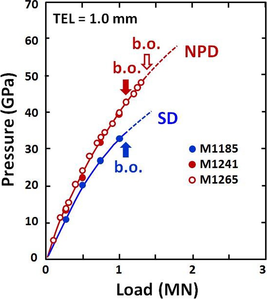
Pressures achieved in the first series of the present experiments as a function of press load. Blow-outs happened at the similar press loads of ∼1.1 MN when the second-stage anvils of WC were used (runs M1185 and M1241) regardless of the anvil materials for the third-stage anvils. In contrast, significantly higher load of up to 1.4 MN was applied when the second-stage WC anvils were replaced by those made of SD (run M1265). Note that the achieved pressure using third-stage NPD anvils was about 20% higher than that reached using SD anvils at 1.0 MN.
As shown in Fig. 4 and Table 2, we found the efficiency of pressure generation using NPD anvils became significantly higher than that using SD anvils with increasing the press load, and the difference reached about 20% at a press load of 1.0 MN (i.e. 33.0 GPa for SD anvils versus 39.5 GPa for NPD anvils; Table 2). The materials of the second-stage anvils (WC and SD) seem not to affect the efficiency of pressure generation, as is seen from the results of runs M1241 and M1265 (Fig. 4). The highest pressure of ∼50 GPa in the first series of the experiments was achieved using the NPD third-stage anvils combined with the SD second-stage anvils (M1265).
In the second series of experiments, we introduced WC third-stage anvils shrinkage fitted to hardened steel frames (run M2015; Fig. 2b) to further expand the applicable press load, in addition to the slight changes in the dimensions of the gasket. This actually led to a substantial increase in the applicable load to ∼3.4 MN (Fig. 5), which is about three times higher than the limit (∼1.1 MN) using the WC third-stage anvils without shrinkage fitting. As a result, the highest pressure of ∼88 GPa was achieved in the 6–6–8 KMA with the NPD third-stage anvils, as shown in Fig. 5 and Table 2. This is more than 50% higher than that reached using the SD anvils (∼56 GPa) with the same cell assembly (run M2020).
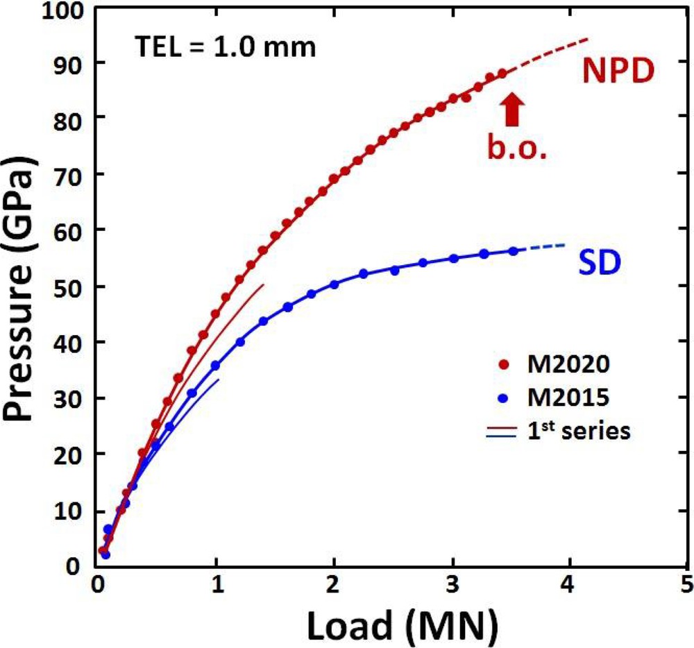
Pressures achieved in the second series of the present experiments as a function of press load, compared with those of the first series runs (thin curves). The use of shrinkage fitted WC for the second-stage anvils, in addition to some modifications in the gasket sizes, remarkably increased the applicable press load to ∼3.4 MN, and achieved pressures of ∼88 GPa when NPD was used as third-stage anvils. This pressure is about 50% higher than that achieved using SD anvils with the identical cell assembly.
Fig. 6 shows X-ray radiographic images of the sample, illustrated in Fig. 6a, through the NPD anvils (Fig. 6b; run M2015) and SD anvils (Fig. 6c; run M2020) under the same press load of 3.0 MN. The sample shape can be clearly seen through the NPD anvils as compared to that through the SD anvils which contains a few wt.% of Co. It should be noted that the two anvils have different edge lengths of 6 mm (NPD) and 14 mm (SD) in these runs, and accordingly the length of the X-ray path through the SD anvils is ∼2.3 times longer than that through the NPD anvils. Nevertheless, the advantage of using NPD anvils in X-ray imaging relative to SD anvils is quite obvious.
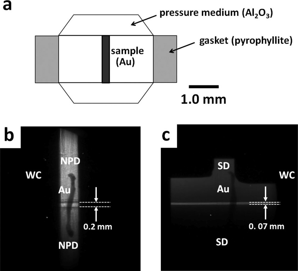
Illustration of a cross section of the cell assembly (a), and X-ray images of the samples in runs M2015 (b; NPD anvils) and M2020 (c; SD anvils) at a press load of 3.0 MN. The shape of the Au sample can be clearly seen through the NPD anvils. It should also be noted that the gap between the NPD anvils (b; ∼200 μm) is substantially wider than that between the SD anvils (c; ∼70 μm) at the same press load.
It is also noteworthy that the gap between the upper and lower NPD anvils (∼200 μm) are substantially wider than that for the SD anvils (∼70 μm) under the same press load (3.0 MN), as shown in Fig. 6. This is because of the smaller elastic deformation of NPD anvil relative to that of SD anvils, as NPD is much stiffer (Young's modulus E = ∼1140 GPa; Chang et al., 2014) than SD (E = ∼900 GPa; e.g., Petrovi et al., 2012). As the anvil gap gets smaller with increasing pressure, the diffraction measurements through the gap tend to become difficult at pressures higher than 100 GPa using SD anvils (Yamazaki et al., this issue). This problem can be substantially reduced by using harder NPD anvils with less elastic deformation.
Fig. 7 compares the X-ray diffraction profiles of the gold sample through the anvil gap (Fig. 7a) and SD anvils (Fig. 7b) in run M2020 and also through the anvil gap (Fig. 7c) and NPD anvils (Fig. 7d) in run M2015, all taken for 180 s at a press load of 1.75 MN. It is seen that high-quality X-ray diffraction data can be obtained through the NPD anvils (Fig. 7d), while only a poor diffraction profile is available via the SD anvils (Fig. 7b), particularly for the lower energy range due to absorption by the metal binder in the latter anvils. For instance, the intensities of the diffraction peaks at ∼50 keV and ∼100 keV through the SD anvils (Fig. 7b) are ∼1/100 and ∼1/10, respectively, relative to those through the NPD anvils (Fig. 7d). Moreover, the intensities of the diffraction peaks from the sample through NPD anvils (Fig. 7d) are comparable to those through the anvil gap (Fig. 7c). Thus, even if the anvil gap becomes infinitesimally small, X-ray diffraction measurements would be continued through the NPD anvils under very high pressure.
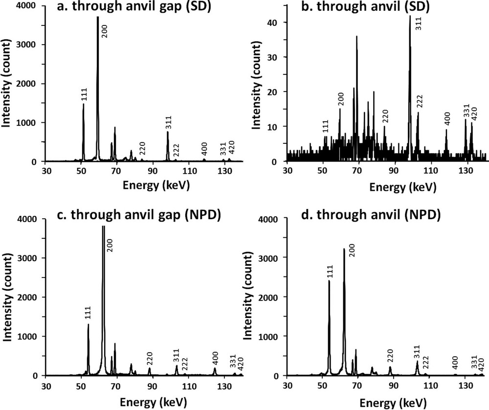
X-ray diffraction profiles of the Au sample through anvil gap (a) and SD anvils (b) in run M2020, and those through anvil gap (c) and NPD anvils (d) in run M2015, taken for 180 s at a press load of 1.75 MN. Only very poor diffraction profiles are obtained through the SD anvils (b), while the quality of the diffraction profiles through the NPD anvils (d) is high enough for the identification of the phases present and unit-cell volume measurements of the sample, similar to those through the anvil gaps (a, c). The unindexed peaks are mostly diffractions from alumina pressure medium and characteristic X-rays from gold. Note that the relative intensities of the diffraction peaks from the gold sample may somewhat vary as we used a rolled foil, which may suffer a certain deviatoric stress upon compression at room temperature.
4 Discussion and future perspectives
The present study demonstrates that NPD is a potentially important ultrahard material of “third generation”, after WC and SD, for KMA. Although the maximum pressure has been limited to ∼90 GPa using a combination of NPD cubes with 6 mm edge length and of shrinkage fitted WC anvils, we could easily expand the applicable press load by replacing the second-stage anvils with the shrinkage fitted SD anvils, which should have significantly higher compressional strength than the bare SD second-stage anvils without shrinkage fitting. Moreover, the largest NPD cubes that we can produce in BOTCHAN-6000 are those with an edge length of 7 mm, on which we could apply press loads about 1.4 times higher than those on the NPD cubes used in the present study. This suggests that the applicable press load is expanded to ∼5 MN, and that the pressures exceeding 100 GPa would be readily achieved according to the pressure-versus-load relation shown in Fig. 5.
Further higher pressures could also be realized by using the NPD anvils. Although we used the gasket and the pressure medium optimized for the SD experiments in terms of materials, designs, and dimensions, these should be largely modified to fully utilize the extreme hardness of NPD. Actually, the use of harder gasket and pressure medium as compared to those for the KMA using WC anvils was the key to the successful achievement of pressures beyond 50 GPa using SD anvils (e.g., Ito et al., 2005; Tange et al., 2008a, b). The optimization of the gaskets/pressure medium for NPD anvils, combined with the use of larger NPD anvils and the suitable second-stage anvils, should thus lead to pressures far higher than that of the mantle-core boundary of the Earth (∼136 GPa) in KMA.
The high transparency of NPD to X-ray and visible light would also lead to some advanced technology in the KMA experiments. The high X-ray transparency has great advantages in various measurements wherever the sample imaging is important, such as X-ray micro-tomography (Yu et al., 2016) and the measurements of ultrasonic sound velocity (Li et al., 2004), density from X-ray absorption profile (Katayama et al., 1998), and viscosity using falling sphere method (Kanzaki et al., 1987) under high pressure. The high X-ray transparency of NPD, in addition to its ultra-hardness, allows us to adopt more flexible cell designs for the diffraction measurements on the sample and the pressure reference material, particularly at very high pressures where the anvil gap becomes extremely small.
On the other hand, the high optical transparency of NPD should lead to the temperature measurements based on optical spectroscopy as are used in the laser-heated diamond anvil cell (e.g., Mao and Mao, 2007), which allows us to cross-check the temperatures determined by thermocouples, where there are some uncertainties because of the unavailability of the pressure effects on the electromotive force of the thermocouples under very high pressure. Measurements based on Raman spectroscopy of diamond and ruby fluorescence may also be conducted through the NPD anvils in KMA, which provide pressures independent of those determined based on in situ X-ray diffraction measurements for pressure reference materials.
Another potentially important technology of application of NPD to KMA is the use of this material as the third-stage anvils of the 6–8–2 system (Kunimoto et al., 2008). We developed this technique and confirmed pressures up to ∼125 GPa and temperatures up to ∼1300 K (Kunimoto and Irifune, 2010), but the very small sample volumes under such pressures hindered precise identification of diffractions from silicate minerals relevant to the Earth's interior. The recent success of producing extremely high pressures in double-stage diamond anvil cells using NPD as the second-stage anvils (Dubrovinskaia et al., 2016; Dubrovinsky et al., 2012; Sakai et al., 2015, 2018) encourages challenges for multi-megabars and even further higher pressures in KMA using the 6–8–2 system with NPD anvils, combined with more focused X-ray beams having higher brightness compared to those available in existing synchrotron beamlines for large-volume press experiments.
Acknowledgements
The authors thank F. Isobe for synthesizing some NPD materials using BOTCHAN-6000 and A. Kurio for laser cutting of the NPD rods to the anvils. The present study is supported by the JSPS Grants-in-Aid for Scientific Research (S) (No. 25220712) and the MEXT Grants-in-Aid for Scientific Research on Innovative Areas (No. 15H05829).