

 CC-BY 4.0
1. Carbon sinks, a necessary remedy for combating climate change
The Paris Agreement was the first legally binding global agreement on climate change, adopted at the Paris Climate Conference (COP21) in December 2015 [UNFCCC 2015]. With the main objective of keeping the average global temperature rise well below 2°C compared to pre-industrial levels (over the reference period 1850–1900), and limiting it as much as possible to 1.5°C, the Paris Agreement also aims to strengthen capacities for adaptation and resilience to the effects of climate change, as well as to implement financial flows adapted to these objectives.
Article 4 of the Agreement indicates that all States that have ratified the Agreement shall aim to reach global peaking of greenhouse gas emissions as soon as possible and to undertake rapid reductions thereafter in accordance with best available science, so as to achieve a balance between anthropogenic emissions by sources and removals by sinks of greenhouse gases in the second half of this century. Achieving this balance means achieving what is called 'carbon neutrality', which consists of offsetting via carbon sinks the share of incompressible CO2 emissions that we cannot or do not yet know how to reduce satisfactorily. "Carbon neutrality in 2050" is the main objective chosen by France for its climate change mitigation policy, in application of to the Paris Agreement [CESE 2020]. This policy is now enshrined in law [French Republic 2019]. Furthermore, on March 4th 2020, the European Commission presented a climate law proposal to ratify the European Union's objective of carbon neutrality by 2050 [European Commission 2020].
There are several types of carbon sinks. First, the so-called natural carbon sinks, but for which human intervention is necessary to preserve or strengthen them. Growing forests constitute a carbon sink, capable of removing CO2 from the atmosphere through photosynthesis. Soils and agricultural lands that store organic matter (humus, plant debris) can also be carbon sinks, as well as oceans that trap atmospheric CO2 via its dissolution in water. There are also so-called technological carbon sinks, essentially the geological carbon sink, which consists of capturing CO2 not in the atmosphere, where it is very diluted, but in the fumes of factories that spew it out in abundance at higher concentrations, in order to store it underground in a geological layer more than a kilometer deep.
Natural carbon sinks are already under strain. Until the beginning of the industrial revolution, the natural exchanges between the atmosphere, vegetation, soils, and oceans were balanced, which explains why the atmospheric content of CO2 remained constant for several thousand years before 1750. Since then, however, massive use has been made of fossil fuels extracted from the subsurface, such as oil, coal, and natural gas, which are very rich in carbon. By burning these fossil fuels for electricity generation, heating, industry, and transportation, carbon combines with oxygen in the air to form carbon dioxide (CO2), which is then emitted into the atmosphere. Fortunately, half of these CO2 emissions have been reabsorbed by vegetation and oceans, i.e. the natural carbon sinks. However, the other half has accumulated in the atmosphere, leading to climate change. The CO2 content of the atmosphere, which had remained below 280 ppm (parts per million, or 0.028%) for more than 800,000 years, has thus increased to 410 ppm (0.041%) in about 200 years and continues to rise even faster over time. In the face of this unprecedented increase, natural land and ocean carbon sinks, even if stimulated, will not suffice. Their capacity is limited and some undesirable consequences are already being felt, such as ocean acidification caused by the dissolution of CO2 in water that disturbs marine ecosystems. Moreover, these carbon sinks are weakened by global warming, as demonstrated by the increasing destruction of forests by tornadoes and fires, for example. There is therefore even a risk that these natural carbon sinks will become carbon sources.
It is therefore also necessary to activate the geological carbon sink, which means returning the carbon that was extracted in the form of coal, oil, or natural gas to the subsurface, in the form of CO2. CO2 can thus be permanently trapped in a way that is not weakened by global warming. This is the technology known as CO2 Capture and Storage (CCS), or Carbon Capture and Storage, on which the IPCC published a special report in 2005 [[IPCC 2005]; [ADEME, BRGM, IFP 2007]].
The following article explains how to develop a geological carbon sink, presents the first CCS facilities in operation in the world, and describes the research underway to enable the more widespread implementation of this carbon sink, including in France. It calls for solutions on a territorial scale and explains why the geological carbon sink can offer flexibility to countries and territories in order to achieve carbon neutrality and enable a just and inclusive energy and ecological transition.
This article largely reproduces the article written by the author in the book "No(s) Futur(s)" ("Our Futures" in English) published in bookstores in July 2020, an anthology of scientific and fictional texts intended to raise awareness, inform, and produce stories around the challenges of climate change (Figure 1, [Czernichowski-Lauriol 2020]). This book is prefaced by its godmother, Valérie Masson-Delmotte, Vice-Chair of IPCC Group 1, a group that evaluates the scientific aspects of the climate system and climate change.
2. How to create a geological carbon sink?
CO2 must first be captured in industrial flue gases as this is where it is emitted in large quantities and at a high concentration (from 4% to 40% or more). Capturing it directly in the air where it is extremely diluted (0.04%), or from mobile sources such as car exhaust pipes, is much more complex and costly, although research in this direction is underway. Carbon capture consists of separating CO2 from other compounds present in industrial off-gases (mainly nitrogen from air, etc.). This step can be achieved via different techniques already proven or under development to improve performance and reduce costs. For example, the capture of CO2 by chemical absorption in amine solvents is conventionally used for the treatment of natural gas, which naturally contains some.
Then the CO2 has to be transported to an adequate storage site; it cannot simply be injected anywhere in the subsurface as the location needs to be geologically suitable. The captured CO2 is compressed at high pressure (>73 atm), thus passing from a gaseous state to a dense state comparable to a liquid. It can then be conveyed via pipelines to the storage site. These will have to be built to connect CO2 emitters to storage sites. In certain cases, it may be possible to convert gas or oil pipelines into CO2 pipelines. It is also a proven technology, as several thousand kilometers of CO2 pipelines are already in operation around the world, mainly in North America and for injection into petroleum reservoirs. Transportation by ships, barges, and trucks may also be considered.

Cover of the book "Nos Futurs (Our Futures): Imagining the Possibilities of Climate Change". Published in July 2020 by Editions ActuSF.
Finally, CO2 is injected by drilling beyond 800m in depth into deep, porous, and permeable geological layers of limestone or sandstone. The CO2 is stored in the pore space between minerals, repelling the salty water which is generally present there (Figure 2). CO2 remains in a dense state called a "supercritical state" at these depths because its temperature and pressure are higher than those of its critical point (31 °C, 73 atm). It is then neither in the gaseous state nor in the liquid state, but has intermediate properties between the two, in particular a density close to that of a liquid and a viscosity close to that of a gas. This makes it less prone to rise to the surface than a gas and maximises the amounts storable in a given volume of rock. Since its density is slightly lower than that of the salty water present in the storage reservoir layer, it tends to migrate slowly towards the top of this layer; hence the need for the presence of an impermeable clay layer above, called caprock, which blocks its upward movement (structural trapping). Other trapping mechanisms are involved. Dense CO2 is also trapped as isolated bubbles in the pores of the rocks traversed due to capillary forces (residual trapping). Over time, some of the CO2 dissolves in the salty water (dissolution trapping). The water enriched in dissolved CO2 then becomes slightly heavier and tends to migrate down the storage reservoir layer. All of this contributes to trapping CO2 more and more effectively. Mineralogical reactions induced by dissolved CO2 that acidifies water can even sometimes lead to the formation of carbonate minerals, which traps CO2 in solid form (mineral trapping). The relative importance of these four trapping mechanisms varies over time and is dependent on the natural characteristics of each storage site as well as the injection conditions.
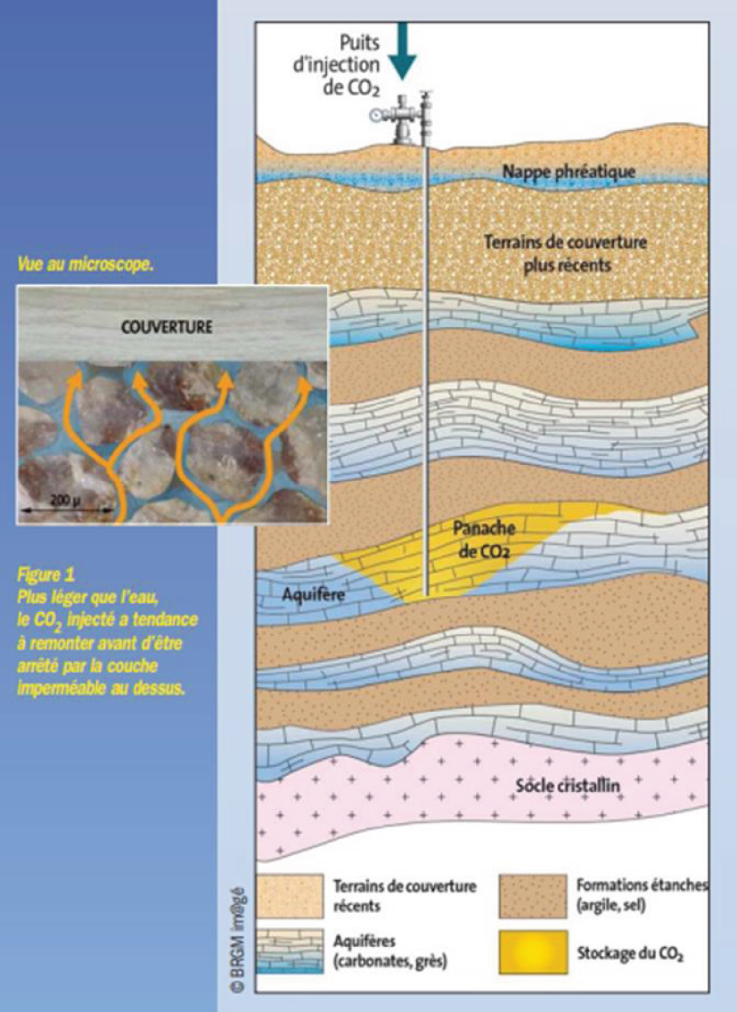
Principle of CO2 storage in deep geological layers (© BRGM).
Implementing the geological carbon sink therefore requires assembling a complete chain of CO2 capture, transport, and storage. The closest analogy with a controlled and globally widespread industrial practice is that of the production of natural gas (CH4, methane), then its purification, transport by pipeline, and seasonal storage in a gaseous state underground, in a saline cavity or in the porosity of an aquifer rock covered with an impermeable caprock. It is therefore realistic to think that it will be possible to master the large-scale deployment of CO2 capture and storage, even if there are notable differences between the two sectors which must be taken into account due to the different nature of the gas and the duration of storage.
3. Nature shows us that it is possible to store CO2 underground
Nature shows us that this is feasible because there are numerous natural underground reservoirs of CO2 of volcanic or mantle origin that are several million years old. This proves that geological formations can sustainably trap very large quantities of CO2 [Pearce et al. 2004]. In southeastern France, for example, eight natural CO2 reservoirs were discovered between 2 and 4 km deep during oil exploration in the 1960s (Figure 3; [Czernichowski-Lauriol et al. 2002]). When drilling was carried out with the assumption of having discovered oil or natural gas, it was surprising that the trapped fluid was in fact CO2 (66 to 99% CO2 depending on the case). This CO2 had risen from the depths of the earth through faults and accumulated under a clay cover in the porosity of the underlying rock. At other places it has dissolved in the waters present in the pore space of the rocks encountered. Some of these have become exploited carbonated waters (Vichy, Badoit, Perrier ...). Elsewhere, it was able to migrate to the surface and escape into the air through a hole or crack. These gaseous emanations, called mofettes, are often natural curiosities, such as in Neyrac in the Ardèche department and la grotte du Chien ("the dog cave") in Royat in the Puy de Dôme department. In some countries, there are even geysers releasing water and CO2 intermittently. The best known are the Andernach geyser in Germany and Crystal Geyser in Utah in the United States, which are tourist attractions.
In most cases, natural releases of CO2 at the ground surface do not cause any damage because CO2 is dispersed in the air. CO2 is neither flammable nor explosive, unlike methane. It is an odourless gas that we breathe constantly and even swallow with carbonated drinks. It is not toxic at low doses, unlike carbon monoxide (CO), which results in unconsciousness as soon as its concentration in breathed air exceeds 0.1%. As long as the concentration of CO2 in the air, usually 0.04%, does not exceed 1%, there is no physiological effect. Above this, there is an increase in the concentration of CO2 in the blood and a relative depletion of oxygen in the air. This can result in an accelerated respiratory rhythm and headaches, and, for higher concentrations and prolonged exposure, loss of consciousness and even death. The risk of asphyxiation becomes real only if the leak occurs at the level of a confined space (cellar, cave, poorly ventilated building...) or a depression in the ground. This is because CO2 is a little heavier than air and can accumulate in low areas. Otherwise, the gas disperses into the atmosphere, which clearly nullifies the ecological objective but does not cause a health catastrophe.
Acute CO2 poisoning in an open environment is only possible as a result of volcanic phenomena releasing hundreds of thousands of tons of CO2 at once, a flow rate that is not relevant to even the most serious leaks that could emanate from CO2 storage. The Lake Nyos disaster in Cameroon in 1986 is in everyone's minds. It was caused by the violent outgassing of CO2 of volcanic origin which was stored in dissolved form in the deep waters of this crater lake, suddenly releasing more than one million tonnes of CO2 overnight. Being heavier than air, it descended into the entrenched and relatively confined valleys of the surrounding area. More than 1700 people, livestock, and large numbers of animals died within 24 hours within a 14 km radius. In the case of CO2 storage, there is only a borehole blowout which could release a great deal of CO2 at once, but the flow would be much less and solid dry ice would form on the surface due to the cooling caused by the large pressure drop. There is therefore very little risk of causing fatal accidents.
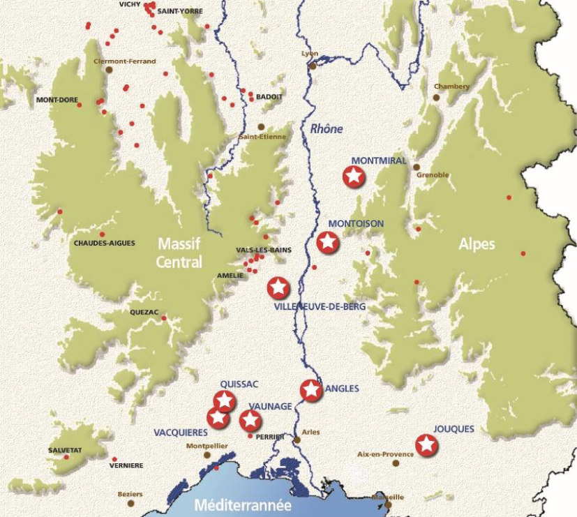
Natural CO2 reservoirs in the French carbogaseous province (large stars). The red dots correspond to exploited carbonated waters (beverages, thermal springs). French Geological Survey (BRGM)
If CO2 were to escape from storage through natural faults and fractures in the caprock or overlying layers, the leakage would be more modest, would not necessarily reach the surface (or would take a long time to reach), and would manifest itself in isolated mofettes, probably aligned along fault lines. This is what is observed at a natural site in Italy (Latera, in Tuscany) where CO2 of volcanic origin arrives to the surface at the level of a grassland [CO2GeoNet 2008]. The gas releases are weak and very localised, aligned on a fault line or at an intersection of faults. They look like clear spots in the middle of the greenery due to a very localised modification or disappearance of vegetation. If these releases stopped, the vegetation could come back. In the event of a localised leak in the water table, it is not CO2 that is in itself dangerous, since we drink natural carbonated water, but the impurities that accompany it and the possibility that the concentration of certain metals (lead, zinc, manganese, aluminum, arsenic, etc.), naturally present in very small quantities in the groundwater, may increase because of the mineralogical reactions induced by the acidification of the water. This would then affect the quality of the water, which may no longer be compliant with drinking water standards. If the leakage is stopped, the chemical re-equilibration between water and minerals should lead to re-trapping these elements.
In any case, CO2 storage must be designed to prevent all leakage outside the storage reservoir and be monitored to ensure that this is the case, while also providing for measures to be taken in the event of abnormal behaviour. Hence the importance of a series of preventive and corrective measures.
4. How to ensure that CO2 storage is carried out safely for the population and the local environment?
How to choose a good site? What are the guidelines to be followed to ensure, with a sufficient level of confidence, that CO2 is safely stored in the storage formation in the long term? There are five main categories of measures distributed throughout the storage project, from its initial design, to the cessation of injection, and through the end of the monitoring phase that continues thereafter to verify that the site is evolving towards long-term stability (Figure 4; [Bouc et al. 2012]).
The first is based on a good selection and characterisation of the storage site: the reservoir rock and the caprock must have adequate natural characteristics in terms of porosity, permeability, thickness, and lateral extent. It is also important to know their chemical, thermal, and mechanical properties, which will also determine storage performance. It is necessary to identify if there are faults, particularly in the caprock, and pre-existing wells in the area. Storage in an area where the seismicity is too high must of course be avoided, as it could affect the integrity of the wells and the caprock, or reactivate faults that are too close. It is also necessary to characterise the geological formations located above, including groundwaters, as well as the surface environment; one must avoid any nuisance (leakage, ground movement) that would locally affect ecosystems or human activities. This initial characterisation will also establish an indispensable baseline against which any measurement made during or after the end of the injection can be compared in order to know whether an observed change is induced by the storage activities or results from another cause.
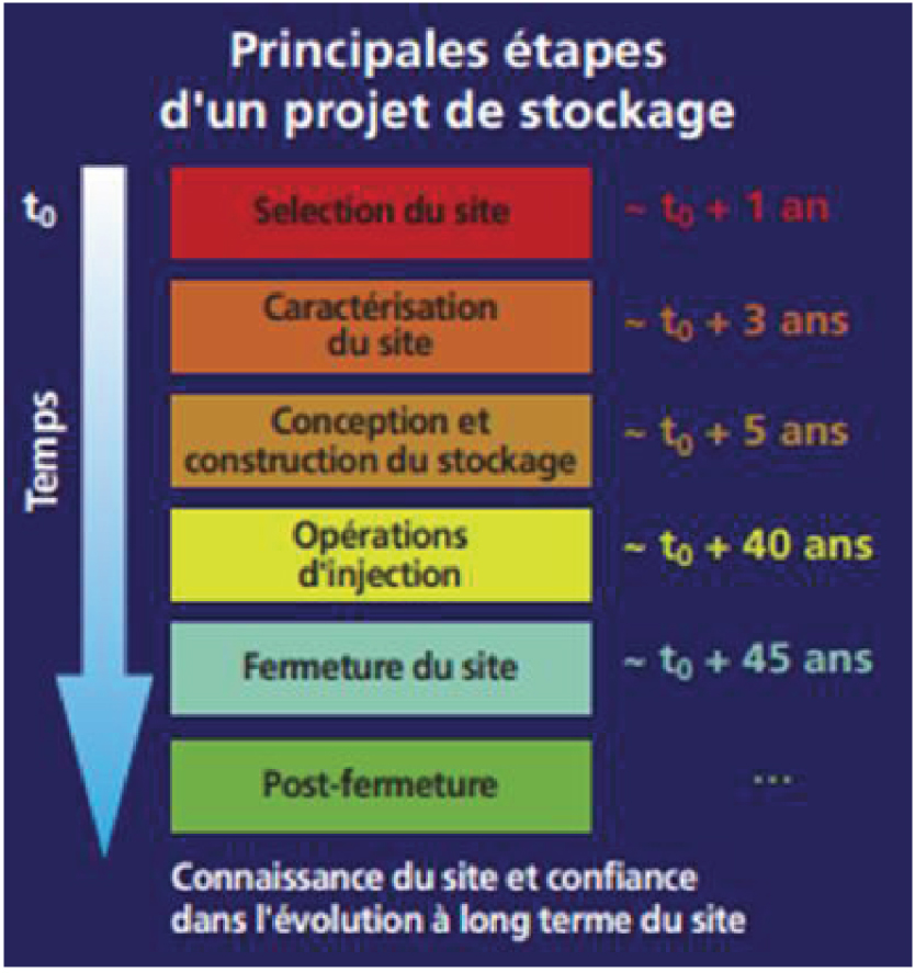
The main stages of a CO2 geological storage project [CO2GeoNet 2008].
The second category of measures must evaluate how to perform high-performance storage. Laboratory experiments and numerical modelling are carried out to simulate the injection of CO2 into the reservoir and the long-term storage behaviour well after the end of the injection, over thousands of years. They must take into account all the information acquired during the initial characterisation of the site, but also the characteristics of the CO2 to be injected in terms of quantity (tonnes per day) and quality (% and nature of impurities). Depending on the capture process used and the type of flue gases treated, there may be a few % of impurities in the CO2 (N2, O2, SOx, NOx, etc.). The objectives are to estimate how much CO2 can be stored (storage capacity); to design of the injection operations (number, position, inclination, and type of injection wells) in order to store without causing mechanical damage that could fracture the caprock or be felt on the surface; and to predict where the dense CO2 and the dissolved CO2 will be distributed over time in the host formation, as well as the relative proportion of the four trapping mechanisms. The uncertainty margins in the forecasts are then evaluated to take into account the necessarily imperfect knowledge of the natural geological environment and the assumptions made for the models, which are always simplified representations of reality. Storage operations are therefore sized with safety margins so that no undesirable phenomena occur and impact vulnerable elements.
The third category of measures must ensure that the injection and closure operations of the site are carried out correctly: it is essential to continuously measure the injection pressure, flow rate, temperature, and composition of the injected CO2. By using geophysical methods (seismic, gravimetric, electrical, electromagnetic, etc.), it is also possible to indirectly measure and then map the distribution of the dense CO2 plume and the changes that occur in the reservoir. In particular, it must be ensured that the pressures within the reservoir always remain below the fracturing pressure of the caprock and do not induce microearthquakes or deformations perceptible at the surface. The initial modelling is refined and improved by taking into account all the parameters measured during injection so as to describe the storage behaviour as accurately as possible. At the end of the injection, the well is sealed by injecting a durable cement into the borehole over a large cumulative height to prevent any rise in CO2.
The fourth category of measures concerns the careful monitoring of all elements that could be impacted by the storage system as part of its normal operation or in the event of failure. These include not only the storage reservoir itself but also the caprock, the boreholes, the overburden, the groundwaters, the surface of the ground or seabed, and ecosystems. This is to investigate whether there are CO2 leaks or to identify possible impacts related to storage, hence the importance of having established a baseline before injection. Different methods of soil and subsurface measurement and investigation are combined to be able to detect, locate, and quantify CO2 and induced changes, or to verify that there are none. Monitoring should be very active during the injection and then continue after the end of the injection. It can then be lightened reduced because of the progressive relaxation of the imbalances generated by the injection. Then it can be stopped if observations and models show in a convergent manner that the storage system is evolving towards long-term stability and that the risks of an altered course of evolution are very unlikely. The storage system will then be similar to a natural CO2 reservoir.
The fifth category of measures concerns the control of risks in the event of unforeseen storage behaviour. Whether leaks or mechanical disorders, it is necessary to be able to understand their causes and estimate the seriousness of their consequences, which depends on the extent of the phenomenon and the presence of vulnerable elements near the storage facility, namely people, human infrastructure, and natural ecosystems. For example, in the case of a detected earthquake, it will be important to know whether it is due to natural seismicity or whether it is seismic activity induced by injection operations. In the event of a surface CO2 leak, to assess the severity for human populations, it is necessary to measure the concentration of CO2 and associated substances in the air, and to carry out simulations to see how it disperses in the atmosphere and whether it can accumulate in part in low or poorly ventilated areas. Risks are highest during the injection period, but they can be easily controlled. Over the long term, the level of risk decreases over time, as the pressure increase caused by the injection dissipates gradually due to natural attenuation processes (dissolution in reservoir water, mineralisation, etc.) until stability is achieved.
In conclusion, it is clear that risk management depends first and foremost on preventive measures, such as a good choice of site and properly carried out injection and monitoring operations. Each site must be subject to a detailed risk analysis and provide for the corrective measures to be put in place in the event of irregularities. It is essential to be able to detect any deficiencies as early as possible via suitable monitoring networks. Numerous monitoring methods have been developed to be able to detect, locate, and quantify any anomaly in all media: in the boreholes, the reservoir, the caprock, the overlying rocks (above the storage system), the water table, the soil surface or the seafloor, and the ecosystems. They are based on geochemical, geophysical, biogeochemical, and even remote sensing techniques (by plane, drone, or satellite). Concerning corrective measures, it is possible, for example, to reduce the pressure in the reservoir by reducing the CO2 injection rate or by extracting salt water. It is also feasible to plug a fault zone or the defective cement of a well. Finally, if it is found that the storage system has unexpected major defects, it may also be decided to stop the injection, and, as an ultimate measure of risk control, to recover the injected CO2 to transport it to a more appropriate storage site or release it to the atmosphere. While the initial goal of CO2 storage was to avoid CO2 emissions into the atmosphere, having to do so for one faulty storage site would not underline the value of activating this carbon sink in many other locations.
Since the 2000s, legal and regulatory texts have been developed to regulate this new CO2capture and storage technology so that it can be safely implemented to contribute to the fight against global warming. Two international conventions whose objective is the protection of the marine environment have been amended to allow the storage of CO2 under the seabed (London Protocol, OSPAR Convention). Since 2009, there has been a European directive on the geological storage of CO2, which was transposed into French law in 2010 and 2011 [European Union 2009]. Recently, international ISO standards have been developed for CO2 capture, transport, and storage. The operator of a storage site is therefore aware of the guidelines to be followed and must apply for a storage permit. As for the national supervisory authorities, they know what to require and what to inspect.
Beyond a period of active monitoring of the storage site by the operator, the transfer of responsibility to the State is planned, some thirty years after the end of the injection, on the basis of three conditions: conformity between models and observations, absence of detectable leakage, and demonstration of the evolution of the storage system towards long-term stability. The operator must dismantle all installations which the State will no longer use and must provide the State with a monitoring plan based on passive measures, i.e. not requiring any special intervention by the State but executed as part of its general tasks (for example, monitoring of drinking water aquifers, seismicity, surface CO2 contents, etc.). The operator must also inform the State of the active measures that were planned during the phase under their responsibility, so that the State can activate them in the event of malfunction. However, in principle, the storage site will evolve to a stable equilibrium state and will become little different from a natural CO2 reservoir over the long term.
5. CO2 capture and storage facilities already in operation worldwide
Currently, there are 19 industrial-scale facilities in operation worldwide, each capturing and storing around one million tonnes of CO2 per year (each equivalent to the CO2 emissions of 250,000 cars over a year) [GCCSI 2019]. Table 1 gives the list of sites and their main characteristics. Ten of these operations are related to the processing of natural gas (methane), as it can contain 10% or more of CO2. Methane must therefore be purified by reducing its CO2 content to below 2.5% before it can be sold. This has been a long-standing practice, long before climate awareness, with captured CO2 being released into the atmosphere. The Sleipner operation in Norway is a world first, as it is the first time that it has been decided for purely climatic purposes to re-inject CO2 into the subsurface (under the North Sea). It has been in operation for almost 25 years.
The 19 CO2 capture and storage facilities in operation worldwide in 2019 [GCCSI 2019]. In deep saline aquifer (AQ) or hydrocarbon reservoir with enhanced oil recovery (HR)
| Continent | Country | CCS Operation Name | Type of industrial installation where CO2 is captured | CO2 Capture Capacity (Mt CO2/year) | Type of CO2 storage | Year operation started | |
|---|---|---|---|---|---|---|---|
| Europe | Norway | Sleipner | Natural gas processing | 1 | AQ | under the sea | 1996 |
| Snøhvit | Natural gas processing | 0.7 | AQ | under the sea | 2008 | ||
| America | USA | Terrell (ex Val Verde) | Natural gas processing | 0.4-0.5 | HR | on land | 1972 |
| Enid Fertiliser | Fertiliser production | 0.7 | HR | on land | 1982 | ||
| Shute Creek | Natural gas processing | 7 | HR | on land | 1986 | ||
| Century Plant | Natural gas processing | 8.4 | HR | on land | 2010 | ||
| Coffeyville | Fertiliser production | 1 | HR | on land | 2013 | ||
| Air Products | Hydrogen production via natural gas reforming | 1 | HR | on land | 2013 | ||
| Lost Cabin | Natural gas processing | 0.9 | HR | on land | 2013 | ||
| Illinois Industrial CCS | Ethanol production | 1 | AQ | on land | 2017 | ||
| Petra Nova | Electricity production from coal | 1.4 | HR | on land | 2017 | ||
| United States and Canada | Great Plains Synfuels Plant & Weyburn-Midale | Hydrogen production via coal gasification | 3 | HR | on land | 2000 | |
| Canada | Boundary Dam CCS | Electricity production from coal | 1 | HR | on land | 2014 | |
| Quest | Hydrogen production via natural gas reforming | 1 | AQ | on land | 2015 | ||
| Brazil | Petrobras Santos Basin CCS | Natural gas processing | 3 | HR | under the sea | 2013 | |
| Asia | Saudi Arabia | Uthmaniyah | Natural gas processing | 0.8 | HR | on land | 2015 |
| United Arab Emirates | Abu Dhabi CCS Phase 1 | Production of steel and iron | 0.8 | HR | on land | 2016 | |
| China | Jilin | Natural gas processing | 0.6 | HR | on land | 2018 | |
| Oceania | Australia | Gorgon | Natural gas processing | 3.4-4 | AQ | under the sea | 2019 |
Two operations are backed by thermal power plants producing electricity from coal: one in Canada since 2014, the first in the world, the other in the United States since 2017. Another is backed by a steel plant in Abu Dhabi since 2016, a world first as well. Two operations concern the production of fertilisers in the United States. Three operations in North America involve the production of hydrogen from coal or natural gas. Finally, there is a plant producing biofuels (ethanol) from corn in the United States, which has been operating since 2017 and is the first in the world to be equipped with a CO2 capture and storage system. It should be noted that in this case, unlike the 18 others, the CO2 emitted is not the result of the use of fossil energy, but of the biological fermentation of the corn, which in order to grow had absorbed atmospheric CO2 through photosynthesis. The stored CO2 is therefore indirectly atmospheric CO2, which amounts to removing CO2 from the atmosphere. This is what the IPCC calls a negative emissions scenario, where CO2 is removed from the atmosphere and stored in the subsurface, keeping in mind that the greater the delay in reducing emissions at the source, the greater the need for this type of solution (IPCC 2019).
As for the storage systems, they are implemented, outside mountainous areas, in sedimentary basins which are the result of sediment deposits in the geological past, leading to an alternation between porous and permeable geological layers filled with water, called aquifers, and impermeable layers of clay, marl, or salt. Near to the surface, these aquifers are filled with fresh water and are often used to provide drinking water; this is referred to as the groundwater. Deep down, the water is increasingly salty and becomes even more salty than sea water, therefore completely unfit for human consumption. Locally, this water is sometimes replaced by oil, methane (CH4), or even natural CO2, trapped in the pores of the rocks. This is how two categories of target sites for CO2 storage are differentiated: The first are deep saline aquifers that offer very large CO2 storage capacities and have a large geographical extent, which favourises the proximity between CO2 emitters and storage sites. The second are depleted or declining oil and natural gas fields, the existence of which shows that a natural trapping structure exists. These are present in a more limited number of places and have lower storage capacities; nevertheless, it is an attractive solution, especially since the injection of CO2 into these reservoirs can facilitate the extraction of some of the remaining hydrocarbons. The process known as "enhanced recovery of hydrocarbons by CO2 injection" has already been widely used in the oil industry for several decades, particularly in the United States but also in Europe.
Of the 19 facilities in operation, five are storing CO2 in deep saline aquifers, the other 14 in oil reservoirs in association with enhanced oil recovery. In this latter case, the costs of CO2 capture, transport, and storage are offset by the sale of the additional oil produced. The two deep saline aquifer storage operations in Norway under the North Sea have been carried out because their costs are offset by the exemption from payment of an existing tax in that country on offshore CO2 emissions. The other three were able to benefit from government subsidies. It is also important to note that 15 of the 19 storage facilties are implemented onshore, while the other four are located under the ocean floor.
6. The costs of implementation and the search for a viable economic model
The costs of CO2 capture and storage are currently between €20 and €120 per tonne of CO2 avoided [ZEP 2015]. Most of the cost (up to 80%) is related to the capture process. However, this is highly reduced if the CO2 is already separated as part of the production process, as is the case for natural gas processing and the production of fertilisers and bioethanol. This explains why this type of industry is already strongly represented among the 19 CCS facilities already in operation. The most significant capture costs occur in installations where CO2 in the flue gas is more diluted, namely in the production of electricity from coal or gas, as well as the production of steel and cement. The cost of transporting and storing CO2 represents a relatively small share of the total project cost, around €10 per tonne of CO2 for onshore storage and €25 for offshore storage. All of these costs are only estimates because they depend on a large number of factors, such as the cost of energy, the transport distance, and the depth of the storage site. As with any type of technology, significant cost reductions are expected as a result of feedback from initial experiences and learning-by-doing, but also through the emergence of new methods and processes that are currently at various stages of development.
For new projects to emerge, the costs of implementation must be offset by revenues. A viable economic model that encourages investment is therefore needed, which is still rarely the case. Few countries or regions have started to monetise carbon to combat climate change, and prices are still too low. The European emissions trading system (EU ETS) was created in 2005, but it has malfunctioned for various reasons (too many allowances allocated free of charge, 2008 economic crisis, fraud, etc.), which means that the price of CO2 on this market has fallen very low, to around €5 per tonne of CO2. This is a primary reason why CO2 capture and storage systems are not yet in operation in Europe, outside Norway. However, this price is starting to rise and reached €25 in early 2020 for this European market. Some countries have introduced a carbon tax, such as Norway since 1991 (value of €57 per tonne of CO2 in 2018), hence the Sleipner CCS operation. France introduced one in 2014, which was worth €7 at the time, €55 in 2018, and should gradually rise to €100 in 2030. The economic conditions favourable to the deployment of the geological carbon sink will be achieved once the price of carbon has risen sufficiently and the cost of CCS has fallen sufficiently in parallel. It should be noted that in the United States, a tax credit called 45Q currently grants a credit of $50 per tonne for CO2 permanently stored in deep saline aquifers and $35 per tonne in the case of storage in a hydrocarbon field with enhanced oil recovery [GCCSI 2020a]. This is a powerful signal that encourages investment and the preparation of new industrial-scale projects.
7. Increased research efforts to allow for implementing of this carbon sink on a massive scale
Via the 19 industrial CO2 capture and storage facilities in operation worldwide, about 40 Mt of CO2 are captured per year and more than 230 Mt of CO2 have already been safely injected into the subsurface. The International Energy Agency estimates, in one of its scenarios, that 107 Gt of CO2 will need to be stored by 2060 to meet climate and energy targets at least cost [IEA 2019]. This means that more than 2000 new CCS operations, if not more, would be required to limit warming to 1.5°C [GCCSI 2020a]. Global storage capacity is in principle sufficient (at least 2000 Gt CO2 as reported by the IPCC in its 2005 Special Report), but this requires a considerable leap in scale! This is why increased research and innovation efforts for this technology have been requested by countries, whether at the international level by the "Mission Innovation" on clean energy launched at the COP21 climate conference in Paris in 2015 [Mission Innovation 2017, 2019], at the European level by the strategic plan for energy technologies developed in 2015 [SET-Plan 2017], and in France where this geological carbon sink is mobilised in a conservative manner, at a rate of 15 MtCO2/year in 2050, in the baseline scenario of the revised National Low-Carbon Strategy [MTES 2020].
A large number of research projects and pilot-scale tests are therefore underway in Europe and worldwide, in order to increase performance, lower costs, further reduce risks, and facilitate deployment in various contexts. Four new CCS operations are already under construction, two in China and two in Canada. Ten others are in the advanced stages of preparation, two of them in Europe. One is in Norway where CO2 will be captured from two plants near Oslo, a cement plant and a waste-to-energy plant, to be stored under the North Sea offshore from Bergen. The other is in the Netherlands where Rotterdam is preparing to be a hub for CO2 collection from various industries with storage located under the North Sea. In addition, the United Kingdom is seriously starting to prepare several CO2 capture projects from several types of industries to also store it under the North Sea [GCCSI 2019].
8. What is the situation in France?
In France, no major project has yet been planned. However, academic and industrial research is very active and a few pilot-scale facilities have been set up to test capture technologies on a small scale, such as at the Le Havre coal-fired power station and soon at the Dunkirk steelworks. In addition, TOTAL has tested in Lacq the first integrated industrial CO2 capture-transport-storage chain in Europe, with a pilot project integrating CO2 capture on a gas boiler, transport through a 27 km pipeline, and storage in a depleted gas field at a depth of 4.5 km (Rousse reservoir near Lacq). More than 51,000 tonnes of CO2 were successfully stored between 2010 and 2013 [TOTAL 2013].
BRGM, the national geological survey, was the first French actor to mobilise, participating as early as in 1993 in the first European research project, entitled "The underground disposal of carbon dioxide", within the 3rd Framework Programme for European Research and Development (FP3) called "Joule II" [Holloway et al. 1996]. At the time, some people already thought that humankind was disrupting the climate and that we should not wait to find solutions until we were sure, otherwise it would be too late. This project concluded by showing the relevance of the concept of CO2 capture at industrial installations and its permanent storage in the subsurface in order to fight against global warming.
Currently, France is coordinating four European research projects under the 8th Framework Programme for Research and Development (FP8) called Horizon 2020. BRGM coordinates the project “Enabling Onshore CO2 Storage in Europe” (ENOS) (2016–2020), which addresses the specificities of onshore CO2 storage (on the continent) close to the emission sites, because Europe cannot rely solely on storage in the North Sea subsurface to reduce its greenhouse gas emissions by at least 80% by 2050 [Gastine et al. 2017]. BRGM also coordinates the STRATEGY CCUS project (2019–2023) which develops scenarios for the deployment of CO2 capture, transport, storage, and utilisation solutions in eight regions that are considered favourable in Southern and Eastern Europe, including the Rhône Valley (from the Fos-Berre/Marseille industrial complex to Lyon) and the Paris Basin (from Dunkirk to Le Havre, Paris, and Orléans). The aim is to provide governments and citizens in the countries concerned (France, Spain, Portugal, Croatia, Greece, Romania, Poland) with an overview of the feasibility of implementing this technology solution in their regions, in close connection with a wide range of local socio-economic activities, in order to help them achieve carbon neutrality. IFP Energies nouvelles is coordinating the CHEERS project (2018–2022) which will test an innovative CO2 capture process at a pilot project in China, as well as the 3D project (2019–2022) which wants to demonstrate another innovative CO2 capture process on the ArcelorMittal steel plant in Dunkirk. The latter project is part of a larger study on the development of the future European CO2 capture and storage hub in Dunkirk - North Sea.
The Centre-Val de Loire region is interested in this technology and is co-financing two regional research projects coordinated by BRGM. The CO2SERRE project (2020-2022) is studying how to capture CO2 emitted by two plants near Orléans, a biomass plant producing heat and power, and a sugar factory, for use in local greenhouses that have growing needs as CO2 stimulates plant growth and improves yields. It is also studying how to store the surplus locally as dense CO2 in a deep saline aquifer. A similar concept was studied in the Netherlands as part of the European research project ENOS (Figure 5). Another project, called GEOCO2 (2019–2020), is studying the potential in the Centre-Val de Loire region of the concept combining the storage of CO2 in dissolved form with the production of geothermal heat, which was the subject of a previous project funded by the National Research Agency [Kervévan et al. 2017].
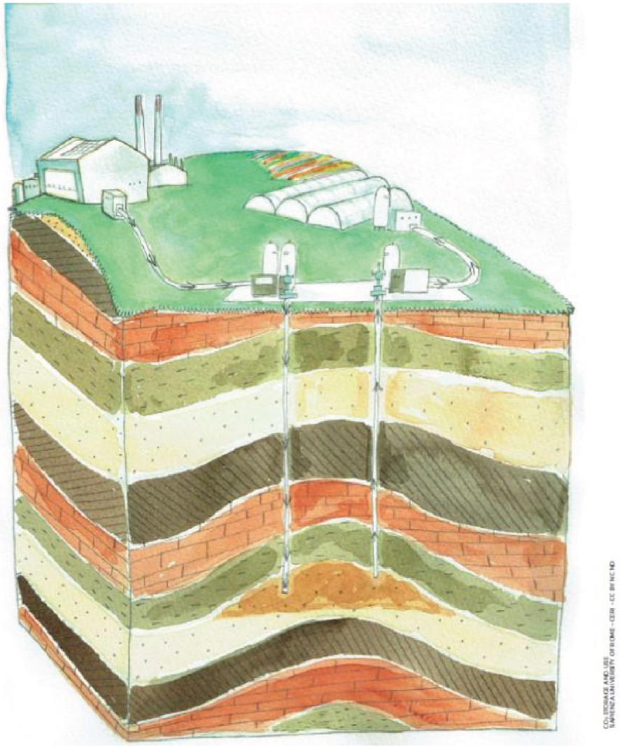
Capture of CO2 from a biomass or gas-fired heating plant operating at full capacity in winter for underground storage, with reproduction in summer of part of the CO2 stored to supply agricultural greenhouses (© Sapienza University of Rome – CERI – CC BY NC ND; [ENOS 2017]).
France is also a founding member of ECCSEL, the European research infrastructure on CO2 capture and storage. Since 2017, it has a legal status (ERIC – European Research Infrastructure Consortium), with five founding countries: Norway (headquarters), France, Italy, the Netherlands, and the United Kingdom. ECCSEL is a distributed research infrastructure that provides researchers and engineers around the world with state-of-the-art research facilities to develop technologies for CO2 capture, storage, and utilisation. ECCSEL-FR, part of the national strategy for research infrastructures [MESRI 2018], brings together all the French facilities and organisations that make it possible to ensure the French presence in the European ECCSEL infrastructure. BRGM has been designated by the French government to ensure its coordination.
BRGM hosts in Orleans the headquarters of the CO2GeoNet association, the European network of excellence on the geological storage of CO2 initiated in 2004 thanks to a European project (FP6) and which became an association in 2008 in accordance with the French law of 1901 [Czernichowski-Lauriol et al. 2009]. The network has grown year after year, and its members currently consist of 29 research institutes in 21 countries. CO2GeoNet, through its four fields of activity (research, training, scientific advice and expertise, information, and communication), has consolidated its role as Europe's scientific voice on the geological storage of CO2. Its flagship event is the Open Forum held every year in Venice to discuss the progress made in the implementation of the geological carbon sink. CO2GeoNet is accredited as a Research NGO by the United Nations Framework Convention on Climate Change and participates every year, since COP21 in Paris, in the World Climate Conference, by organising side-events and exhibition stands to explain what this carbon sink is and how to implement it [Czernichowski-Lauriol et al. 2017]. One of the notable productions of CO2GeoNet is the brochure "What does geological CO2 storage really mean?", available in 30 languages [CO2GeoNet 2008].
In France, more and more academic laboratories, research organisations, and companies are mobilising to develop CO2 capture and storage technologies, as well as various CO2recovery options. Most of them are grouped together in Club CO2, a place for exchanges, information, and initiatives between industrial stakeholders and researchers [Club CO2 2015]. Created in 2002 under the coordination of ADEME, with the support of BRGM and IFP Energies nouvelles, Club CO2 became an association in accordance with the French law of 1901 in 2016, first under the presidency of BRGM followed by IFP Energies nouvelles since 2020. It is important to note that all these French actors are at the forefront of research and innovation in this field at the international level and span all parts of the value chain: capture, transport, storage, and utilisation of CO2. The skills are therefore there for targeting implementation in France and export markets, as highlighted in the national roadmap [ADEME 2011].
It should be noted that the National Low-Carbon Strategy revised in 2020 calls for support for the development of pilot projects and possibly commercial carbon capture and storage (CCS) projects, as well as in carbon capture and utilisation (CCU) with the use of CO2 as a raw material in the manufacture of fuels or chemicals [MTES 2020].
9. Solutions to be considered first at the territorial level
Carbon neutrality in 2050 can only be achieved if we mobilise all possible means and tackle all sectors emitting greenhouse gases: transport, housing, agriculture, industry, energy transformation, and waste. Of course, in the first place, everything must be done to reduce CO2 emissions at their source: consume less energy by promoting energy sobriety and efficiency; develop renewable energies; avoid the use of fossil fuels as much as possible, which is not simple because they still provide more than 80% of total energy production in the world; modify industrial processes and agricultural practices; stop massive deforestation; etc. But for the incompressible share of CO2 emissions that we cannot or do not yet know how to reduce satisfactorily, it will be necessary to activate carbon sinks to offset emissions in order to achieve the carbon neutrality that is essential to limit global warming to below 2°C.
Designing solutions at the territorial level means using the assets of a territory to bring out the best combination of resources, by involving all the actors of this territory (local and regional authorities, decentralised governmental services, companies, universities, research organisations, agencies, associations, citizens, etc.). Depending on the geographical, geological, and socio-economic characteristics of a territory, many variants in the solutions and in the combinations of solutions are possible in order to find what is best suited to the territory. The wider the range of tools, the greater the chances of achieving the objectives that have been set, and the more flexibility to achieve them at a lower cost and in a fair way, i.e. without anyone being left behind. The ability to implement a geological carbon sink can make a significant contribution to all of this.
Various patterns of CO2 capture and storage can be imagined, so it is necessary to develop the most suitable pattern for the territory. For example, it is possible to capture CO2 from all emitters in geographic proximity, as in an industrial area, in order to transport it through the same pipeline to the same storage system. One can also consider having several small storage systems rather than a single large storage system. If no storage option seems possible in the territory, then one can store it in a region or country where it is possible, such as under the North Sea. Alternatively, find ways to use this CO2. For a long time, CO2 has been used to make carbonated beverages, fire extinguishers, as a refrigerant, solvent, etc. For several years, research has been conducted to find other ways of using CO2 as a raw material to manufacture new products (materials, plastics, synthetic fuels, etc.). This could serve as a catalyst for the development of CO2 capture technologies and CCS, in particular due to the economic revenues generated. The entire value chain is called CCUS (adding Utilisation to CCS). However, only a small part of the CO2 emitted (< 5%) can be used, and many of these products only delay emissions, as their lifespan is often short. Storage is therefore essential to reduce CO2 emissions to a level compatible with what is required to combat climate change.
CO2 storage could also be designed to recover geothermal heat from deep geological layers in order to supply a nearby heat network or industry, as studied, for example, in the GEOCO2 project mentioned above. The subsurface temperature naturally increases with depth, for example at 2 km depth it is on average 60 °C. One possible configuration would be to provide a geothermal doublet with a CO2 storage function. France has a good experience of geothermal doublets system in deep saline aquifers. Notably, there are more than forty in operation in the Paris basin since the 1970s. The principle is to pump the hot water present in the deep aquifer through a production well, then to reinject the cooled water into this same aquifer through an injection well after having recovered the heat from it. In new geothermal doublets specially designed for this purpose, it could be envisaged to inject CO2 along with the cooled water, having first dissolved it in this water. All the CO2 would then be stored in dissolved form; there would be no CO2 stored in its dense phase. It would then no longer be necessary to have a caprock to prevent any risk of CO2 being returned to the upper geological formations, as with the "conventional" approach to CO2storage. However, the amount of injectable CO2 is physically limited by the solubility of CO2 in water, so this solution would only be suitable for small industrial emitters scattered over a territory. It is important to note that water acidification associated with CO2 dissolution is strongly mitigated by mineral dissolution and precipitation processes and does not lead to the creation of an underground cavity.
Other synergies are possible with renewable energies. While the coupling of CO2 storage with geothermal energy would offer the possibility of renewable heat production, its coupling with biomass energy would allow active pumping of atmospheric CO2, which is called a negative emissions scenario [IPCC 2019; Hilaire et al. 2019]. Moreover, one of the means envisaged for solving the problem of the storage of excess electricity produced by intermittent renewable energies (wind, photovoltaic) is to electrolyse water to form hydrogen and combine it with captured CO2 to produce synthetic hydrocarbons (methane, methanol, gasoline, DME, etc.), which are easily transportable, distributable, and storable, most of the time using existing infrastructures, and which would replace primary fossil resources. CCS may therefore be useful not only for decarbonising stationary emission sources, but also diffuse emissions from the transport or residential sectors.
The expansion of the use of hydrogen, which is expected to play a major role in the energy transition to decarbonise industry, transport, and building heating, could also be facilitated by CCS technology. Hydrogen is considered the standard of excellence of clean energy because its combustion only generates water. However, the first challenge is to manage to produce it in large quantities. One of the means envisaged is to produce it by electrolysis of water using renewable energies, whose share in the energy mix will continue to increase in the future (this hydrogen is called "green"). Significant research is being conducted to this end. Hydrogen, which is currently mainly used by industry, is 95% produced from fossil fuels (coal, natural gas) - this hydrogen is called "grey". Its production therefore generates CO2, but if it is captured and stored underground, one can produce large quantities of decarbonised hydrogen (this hydrogen is called "blue"). In this scheme, the CO2 emissions previously diffused in the territory would be concentrated at one point, the one where hydrogen is produced, where they could be captured and stored, thus decarbonising the entire chain of subsequent uses. This hydrogen which has been decarbonised via CO2 storage could facilitate the use of hydrogen in the energy mix of tomorrow until green hydrogen is able to take over, or in addition to green hydrogen.
Hydrogen can be injected into gas infrastructures, at a rate of a few percent, in order to gradually decarbonise the content of natural gas distribution networks and their associated uses. This rate could be increased at a later stage by adapting the networks. Specific infrastructures for the transport and storage of hydrogen are also envisaged. For example, the “H21 North of England” project aims at the total conversion of the natural gas network in the North of England into a 100% hydrogen network, in order to decarbonise homes (domestic heating, kitchen), industries, and transport [Northern Gas Networks, Cadent, Equinor 2018]. This project involves the production of blue hydrogen from natural gas with storage of CO2 under the North Sea and storage of H2 in saline cavities on the mainland in England.
10. Conclusion
The fight against climate change and the energy and ecological transition are closely linked. Action is needed to address the major problems of climate, loss of biodiversity, and pollution, which are now occurring on a global scale. However, it is very complex to understand what actions to take because of the multiple interrelationships between human activities. It is important that the actions are carried out in coherence with each other and that the solutions implemented are as effective as possible for achieving objectives, but also the most economical and socially just. All solutions and combinations of solutions must therefore be studied, without any preconceived biases. Returning carbon to the subsurface from which it was extracted is an effective way to reduce incompressible residual CO2 emissions and even remove CO2 that is already in the atmosphere: a virtuous cycle for the environment and the climate. It is the geological carbon sink, which consists of imitating nature by creating CO2 storages similar to the many natural CO2 reservoirs.