Version française abrégée
Les travaux sur l'importance écologique du remaniement sédimentaire par les organismes ou bioturbation sont nombreux en milieu marin et lacustre. Plusieurs méthodes ont été utilisées afin de mesurer l'activité de bioturbation des organismes à travers l'analyse de leurs structures biogènes dans les couches superficielles de sédiments fins homogènes. Qu'il s'agisse du moulage des galeries à l'aide de résine, de la radiographie aux rayons X, ou de la tomodensitométrie axiale, toutes les méthodes disponibles aujourd'hui font systématiquement appel à un carottage non destructif des sédiments. Or, un tel carottage est difficilement applicable au milieu aquatique souterrain, en raison de l'hétérogénéité et de l'épaisseur importante des couches sédimentaires colonisées par les organismes.
Nous avons développé une méthode permettant d'étudier in situ la distribution des structures biogènes dans les couches profondes des sédiments hétérogènes. Cette méthode comprend quatre étapes. Premièrement, un tube en plexiglas est inséré dans les sédiments. La technique consiste à enfoncer par battage un tube métal dont le diamètre interne est de 65 mm (le diamètre externe est de 85 mm). Le tube plexiglas, dont le diamètre externe est de 60 mm, est alors inséré dans ce tube métal. L'espace annulaire entre ces deux tubes n'étant que de 25 mm, il est rapidement comblé par les sédiments lorsque le tube métal est enlevé. Deuxièmement, un caisson cylindrique étanche contenant une caméra vidéo miniature (Sony XC 999P) équipée de quatre spots de 2 W est fixé au bout de tiges plastiques rigides de 2 m, pouvant se connecter entre elles. La caméra est alors descendue dans le tube plexiglas à l'aide d'une crémaillère permettant de choisir la profondeur à visionner avec une précision inférieure à 5 mm. Pour chaque profondeur sélectionnée, une rotation à 360° est effectuée, de manière à obtenir une vision panoramique des sédiments. Les séquences vidéo sont visionnées en direct et enregistrées au format Digital 8 à l'aide d'un vidéo-walkman numérique (Sony GVD 800). Troisièmement, les séquences enregistrées sont exportées sur un ordinateur. À chaque profondeur, une série d'images, présentant chacune un recouvrement d'au moins 40 %, est capturée. La taille de ces images est de 4×2,5 cm et leur résolution de 177 pixels par centimètre. Toutes les images étant distordues en raison des déformations propres à la lentille de la caméra et de la vision à travers la surface convexe du tube, elles sont alors corrigées grâce un algorithme de distorsion préalablement calibré. Ensuite, toutes les images d'une même profondeur sont réunies pour former un panorama. Finalement, ces panoramas sont exportés vers un système d'information géographique et les structures biogènes sont alors cartographiées sous la forme de polygones. Le ratio entre la surface des structures biogènes et la surface totale des sédiments visionnés fournit, pour chaque profondeur, une mesure indirecte de l'activité de bioturbation.
Dans le cadre d'un programme de recherche interdisciplinaire sur l'influence de l'infiltration induite des eaux de ruissellement pluvial sur les écosystèmes souterrains, la méthode de vidéo-prospection a été utilisée afin d'évaluer l'activité de bioturbation de l'oligochète Tubifex tubifex (Müller, 1874) dans le lit d'un bassin d'infiltration. Le lit d'infiltration est composé, sur une épaisseur de 2 m, de galets qui retiennent les sédiments fins (<100 μm) apportés depuis plus de 20 ans par les eaux pluviales. Le remaniement des sédiments fins pouvant limiter la compaction et, par conséquent, le colmatage du lit d'infiltration, il s'agissait de déterminer la densité et la distribution verticale du réseau de galeries creusées par T. tubifex. La vidéo-prospection a permis de montrer que les pores de la matrice de galets étaient entièrement comblés par des sédiments fins d'origine pluviale sur une épaisseur de 80 cm. Ces sédiments fins sont activement remaniés par T. tubifex, puisque deux mois seulement après l'installation du tube plexiglas, le réseau de galeries couvrait en moyenne 10,3 % (écart type : 5,01 ; n=8 profondeurs) de la surface des sédiments. La densité du réseau de galeries ne décroissait pas fortement avec la profondeur, indiquant que les horizons sédimentaires profonds (i.e. 2 m) et suboxiques (oxygène dissous<0,3 mg l−1) étaient également remaniés par T. tubifex. Les recherches en cours visent à déterminer la dynamique temporelle et l'étendue spatiale du processus de bioturbation à partir de vidéo-prospections successives, réalisées en de multiples points répartis dans le lit du bassin d'infiltration.
La vidéo-prospection est une méthode non destructive permettant d'observer des structures biogènes de petite taille (diamètre < 0,05 mm) à plusieurs mètres de profondeur dans les sédiments. L'analyse des séquences vidéographiques peut être optimisée en utilisant des programmes informatiques permettant d'assembler automatiquement les images d'un même horizon (mosaicking) et de délimiter les structures biogènes (différences de contraste entre les galeries et le sédiment). Répétées au cours du temps, les observations devraient permettent de mesurer le taux de renouvellement des structures biogènes. Par ailleurs, il est également possible de combiner vidéo-prospections et pompages faunistiques au sein d'un tube plexiglas perforé afin d'étudier la relation entre la densité d'organisme et celle des structures biogènes. La principale limite de la méthode est son incapacité à fournir une vision tridimensionnelle du réseau de galeries, empêchant ainsi l'étude de l'influence de la bioturbation sur la perméabilité des sédiments. Par ailleurs, la présence du tube modifie nécessairement le comportement fouisseur des organismes. L'absence de longues galeries suggère toutefois que T. tubifex ne se déplace pas préférentiellement le long de la paroi du tube. Malgré ces limites, la vidéo-prospection offre la possibilité d'examiner les structures biogènes dans des milieux tels que les aquifères et la zone hyporhéique des cours d'eau pour lesquels l'importance écologique de la bioturbation est largement méconnue.
1 Introduction
The concept of ecosystem engineer was introduced into the ecological literature to designate those organisms that ‘directly or indirectly modulate the availability of resources to other species, by causing physical state changes in biotic or abiotic materials’ [1]. In marine and freshwater environments, the bioturbation activity of annelids is known to play a dominant role in determining the physical structure of sediments, thereby altering habitat suitability for other species [1], fluxes of water [2], distribution of nutrients [3], dissolved oxygen and organic matter [4], ecosystem processes such as nitrification and denitrification [5], and processing of organic contaminants [6].
Understanding the ecological significance of bioturbation partly relies upon the development of methods that can be used to quantify the density and distribution of biogenic structures within the natural environment [7]. In situ methods involve direct observation by means of a video camera and image analysis of biogenic structures at the sediment surface [8]. Laboratory methods utilize polyester and/or polystyrene resins to mould the network of burrows made by polychaetes within sediment cores removed from the bottom of oceans [7]. Early used as non-destructive methods for the study of physical structures [9] and earthworms burrow system in soils [10,11], X-radiography [7,9,12] and computed axial tomography (CAT) [10,11,13,14] were more recently used in marine sediments to identify biogenic structures within sediment cores. Whereas the former method provides two-dimensional pictures with low resolution and deformations [12], computed axial tomography provides a pseudo-3-dimension representation of sediment cores that enables a quantitative analysis of biogenic structures within the sediment [12,14]. However, the need to obtain undisturbed sediment cores precludes the use of pre-existing methods for identifying biogenic structures within the deep layers of subsurface water environments made of heterogeneous sediments. Thus, studies of actual biogenic structures have been essentially restricted to the shallow layers of soils [9–11] and of sandy and silty environments such as the bottom of lakes and oceans [7,12].
In this paper, the use of a video-camera in transparent tubes is presented as an alternative method for examining in situ the distribution and density of biogenic structures within the deep layers of heterogeneous sediments in which undisturbed cores are hard to be obtained. We describe the principle and technical aspects of the method and provide the results of a field application for which the method was used to determine the density and depth distribution of galleries made by the oligochaetae Tubifex tubifex (Müller, 1874) within the infiltration bed of a stormwater basin.
2 Materials and methods
Downhole viewers have long been used by hydrogeologists for the inspection of borehole casing and location of fractures in bedrock aquifers [15,16]. The method presented below is derived from the work of Niederreiter and Danielopol [17] who developed a mini-video camera system for the observation in situ of unconsolidated sediments and groundwater animals through transparent boreholes. The use of video-logging for quantifying biogenic structures in subsurface sediments requires four successive steps: the installation of transparent tubes, the lowering and rotation of a video-camera for scanning sediments through the tube walls, the numerical treatment of images for correcting deformations and obtaining panoramic views of discrete sediment layers, and the mapping of biogenic structures.
2.1 Installation of transparent tubes
A metal pipe (external diameter: 85 mm; internal diameter: 65 mm) with a highly resistant tip at its lower end is inserted into the sediment either manually by means of a 15-kg hammer sliding along a metal rod or by means of an engine-operated hammer (Fig. 1A). Once the desired depth is reached, the metal pipe is filled with water and a metal bar is used to unscrew the tip of the pipe (Fig. 1B). A transparent PVC tube (Plexiglas XT; external diameter: 60 mm; internal diameter: 54 mm) is lowered slowly within the metal pipe (Fig. 1C). The transparent tube can either be sealed hermetically or perforated with holes to be used as a sampling well. The metal pipe is then removed with a rack-lever arm, while the transparent tube is maintained in its position (Fig. 1D). Because the annular space between the transparent tube and the metal pipe is only 25-mm thick, the sediment collapses along the walls of the transparent tube during or soon after the removal of the metal pipe.
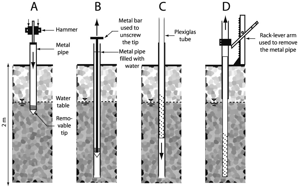
Insertion of a Plexiglas® tube into the sediments. A. Hammering of the metal pipe. B. Removal of the tip. C. Lowering of the Plexiglas® tube. D. Removal of the metal pipe.
2.2 Video logging
The video camera (Sony XC 999P) is enclosed in a vertical position into a watertight cylindrical housing (length: 580 mm; diameter: 46 mm) (Fig. 2A). The camera views the walls of the transparent tubes by means of a mirror inclined at an angle of 45° (Fig. 2B). Light is provided by four 2-W spots. In the field, images are displayed at a rate of 25 frames per second on an 80×60-mm screen and saved in a digital 8 format by a videotape recorder (Sony GVD 800). The camera, lights, and video tape recorder are supplied with a 12-V battery. The camera is held with 2-m long rigid rods and slowly lowered into the transparent tube using a vertical rack-ramp, which enables vertical and rotary movements with a precision of less than 5 mm. The camera can further be stabilized at a fixed distance from the tube walls by means of two distance holders on the front side and two movable pneumatic cylinders on the back side of the camera housing (Fig. 2B).

The downhole viewer. A. Overall view. B. Detailed view of the camera. C. Detailed view of the sediment chamber.
The cylindrical housing also contains a sampling system to collect water, sediment, and animals. A protruding suction tube that appears on the camera field (Fig. 2B) is connected to a chamber located at the lower end of the housing (Fig. 2C). The chamber is connected with PVC tubes to a surface vacuum pump that can be used both for sucking water and injecting water into the subsurface to dislodge sediments and animals. For sampling, the protruding suction tube is positioned in front of a screen hole and stabilized using the movable pneumatic cylinders. Water and sediments are pumped at a discharge rate of approximately 1 l min−1. Water is collected at the ground surface, whereas sediments and animals are retained in the lower chamber by a net (mesh size: 100 μm) and collected once the camera has been removed from the transparent tube.
2.3 Image treatment and mapping of biogenic structures
Video sequences are downloaded onto a computer and individual images are captured. Captured images must be corrected because they are warped by the lens of the camera and the convex surface of the transparent tube (Fig. 3A). The distortion is corrected with a warping algorithm that performs polynomial extrapolations (Fig. 3B). The algorithm is calibrated by superimposing about 20 control points that are marked both on a distorted grid (e.g., a millimetre-scale paper viewed by the camera through the transparent tube) and a non-distorted reference grid. Unusable edges of erected images are deleted. Corrected images are 4.4-cm long and 3.1-cm high, with a resolution of 450 dpi (Fig. 3C). Several corrected images are assembled to reconstruct selected areas of sediments. The resulting view is imported into a geographic information system in order to map the distribution of biogenic structures and to calculate the relative proportion of sediments that are affected by bioturbation.
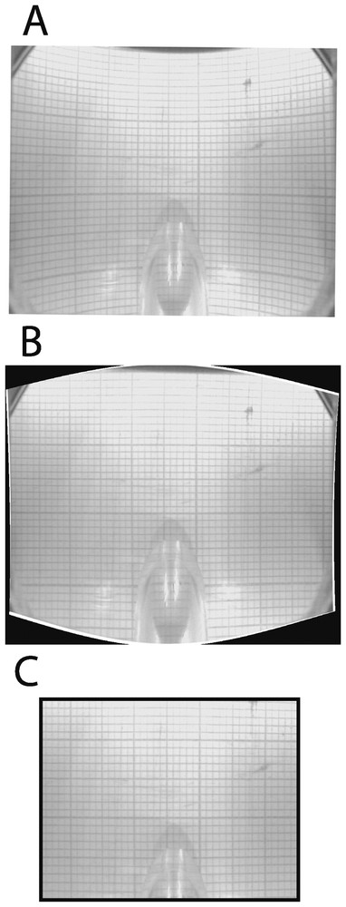
Correction of images. A. Distorted view of a millimetre paper through the transparent tube. B. The same view after correction with a warping algorithm. C. The resulting image after deletion of unusable edges.
3 Field application
Within the framework of an interdisciplinary research project on the effect of stormwater infiltration practices on groundwater quality [18], the method was used to examine the bioturbation activity of the oligochaete Tubifex tubifex within the infiltration bed of a constructed stormwater basin. The infiltration bed is a 2-m-thick layer of cobbles that has retained considerable amounts of stormwater sediment contaminated with heavy metals and organic compounds for the last 30 years [19]. Datry et al. [20] showed that only two species, the oligochaete Tubifex tubifex (Müller, 1874) and the cyclopoid copepod Eucyclops serrulatus (Fisher, 1851) were able to maintain permanent populations in this contaminated and suboxic environment. The density of T. tubifex was found to reach a maximum of 800 individuals per 2 l of pumped water at times when the infiltration bed was replenished with oxic stormwater. Because the infiltration bed was still able to transmit water despite the accumulation of large quantities of stormwater sediments, we explored whether the bioturbation activity of T. tubifex might have slowed down the clogging process by maintaining the porosity and permeability of the cobble layer. Thus, our primary objective was to determine the density and depth distribution of galleries made by the oligochaete T. tubifex within the infiltration bed. The density of galleries was expected to decrease with depth because deep layers of the infiltration bed were almost always suboxic (dissolved oxygen concentration <0.3 mg l−1).
A transparent tube was inserted to a depth of 2 m below the surface of the infiltration bed at a distance of 2 m from the main stormwater inlet. Video-logging was carried out two months after the installation of the tube. The camera was positioned every 10 cm and rotated to scan a 5-cm high layer of sediment. About 40 individual images were captured, corrected with Image Warp module (ESRI.com), and assembled in Adobe Illustrator® 9.0 to reconstruct each layer of sediment (Fig. 4). Polygons were used to delineate the network of galleries, the total area of which was calculated using available scripts in Arc View (version 3.2, ESRI®) (Fig. 4). The same procedure was used to calculate the area filled by stormwater sediment and that occupied either by cobbles or interstices. For each sediment layer, the ratio of the total area of galleries to the area of stormwater sediments was used as an indication of bioturbation density.
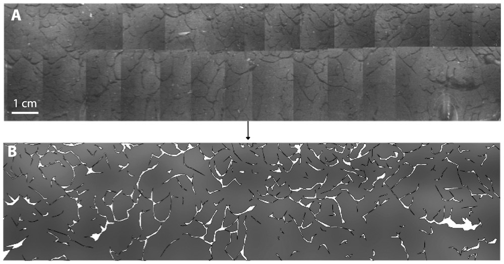
Panoramic view of a sediment layer at a depth of 1.6 m below the surface of the infiltration bed (A) and mapping of the network of galleries made by T. tubifex (B).
The interstices of the cobble layer were found to be entirely filled with fine stormwater sediments (particle size <100 μm) from a depth of 1.4 m below the surface of the infiltration bed (Figs. 5 and 6). We found no evidence of bioturbation in the unsaturated zone of the infiltration bed, because of the low amounts of stormwater sediments. In contrast, a dense network of galleries was observed throughout the saturated zone. Bioturbation density averaged 10.3% (SD=5.01, n=8 depths), with a maximum value of 16.1% at a depth of 50 cm below the water table (Fig. 6). Contrary to our expectation, the bioturbation activity of T. tubifex was not restricted to the shallow layers of the infiltration bed. Indeed, the density of galleries did not show a clear decreasing trend with depth, although the lowest bioturbation densities were measured in the deepest layers of the infiltration bed. These results suggested that the oligochaete T. tubifex could effectively impede the compaction of the infiltration bed by continuously reworking stormwater sediments. Current research is examining the temporal dynamics and spatial extent of the network of galleries by recording video sequences at multiple times and locations within the infiltration bed.
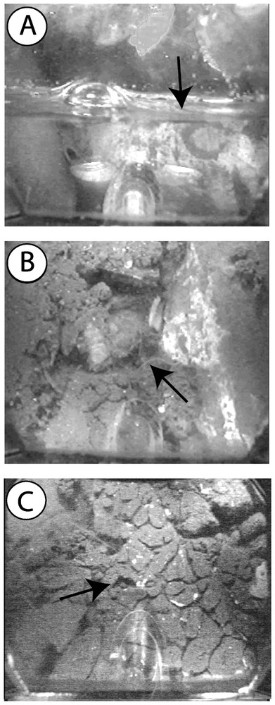
Sediment structure at different depths within the infiltration bed. A. Matrix of cobbles in the vicinity of the water table. B. T. tubifex creeping in a layer partly filled with stormwater sediments. C. Dense network of galleries in a layer entirely filled with fine stormwater sediments.
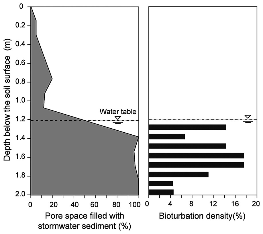
Vertical distribution of stormwater sediments and bioturbation density within the infiltration bed.
4 Discussion
The downhole viewer described in this paper is intended to be used primarily for examining sediment and biogenic structures in deep layers of heterogeneous sediments from which undisturbed cores are hard to obtain. Probably because of the lack of appropriate methods, the potential role of bioturbation in heterogeneous environments such as the hyporheic zone of streams or ground water in unconsolidated sediments has attracted little attention [21–23]. The tube installation technique has been successfully used for more than 10 years to install transparent wells at depths of several meters (up to 10 m, R. Niederreiter, pers. comm.) in unconsolidated sediments [21,24]. The image resolution allows us to detect small-size biogenic structures, the diameter of which does not exceed 0.05 mm (e.g., galleries drilled by tubificid worms). The image treatment is being optimized by using algorithms for assembling individual images of a sediment layer (i.e. mosaic programs that identify areas shared by several images) and delineating automatically the network of galleries (i.e. automatic recognition program based on contrast differences between galleries and sediments).
Video-logging is a non-destructive method that offers several research possibilities. In situ observations can be repeated over time in a tube to determine the life span and spatial turnover of biogenic structures. Whenever necessary, the bacterial biofilm that forms along the inner walls of perforated tubes is removed with a soft brush. However, the use of non-perforated transparent tubes is recommended in subsurface sediments that may yield turbid water inside the tube. In that case, the tube is filled with clean water prior to video-logging. One can also assess the relationships between the densities of biogenic structures and invertebrates by sampling interstitial organisms with a pump after video-logging has been carried out in a perforated tube.
The main limitation of video-logging is its inability to provide a three-dimensional view of biogenic structures. Soil biologists have long emphasized the interest of 3-D reconstruction in bioturbation studies [10,11]. Thus, the method cannot be used to determine the connectivity of the three-dimensional network of galleries, an essential feature for assessing the influence of bioturbation on hydraulic conductivity of sediments. Moreover, the insertion of a transparent tube necessarily affects the exploratory behaviour of animals. Burrowing animals that come into contact with the tube must either turn back or creep along the tube walls. Images recorded from the bed of the stormwater infiltration basin did not reveal the presence of long galleries, suggesting that T. tubifex did not preferentially creep along the tube walls. Despite these limitations, we believe that video-logging is a promising method for assessing the density and distribution of biogenic structures in the deep layers of heterogeneous sedimentary environments.
Acknowledgements
This work was part of the OTHU project (Experimental Observatory for Urban Hydrology) and was funded by the urban community of Lyon (COURLY) and the Rhône-Alpes Region. Mention of trade names or commercial products in this paper does not constitute endorsement or recommendation for use. The address of a Company is given herein for readers interested in further testing of the downhole viewer described in this paper: UWITEC Company, Moosbachweg 10, 5310 Mondsee, Austria (http://www.uwitec.at). We thank C. Robinson for his comments that improved the final version of this paper.


