

1 Introduction
During the course of an investigation involving the isomorphous substitution of divalent cations for Al and/or Si in host framework structures, a new potassium calcium silicate material, CAS-1 (|(Ca4 K4 (H2O)8| [Si16 O38]), was synthesized. Absorption, catalysis and ion-exchange measurements indicated that CAS-1 was microporous [1,2], and the X-ray powder diffraction pattern that the structure was novel.
Scanning electron micrographs (Fig. 1) showed that the crystallites had a needle-like morphology (ca. 100 × 10 × ~1 μm), but none were of sufficient size and quality for single crystal data collection. However, the sample appeared to be well-suited for the application of the texture approach to structure determination that we have been developing [3]. It proved to be possible to prepare a textured sample (with preferentially oriented crystallites), so the necessary X-ray diffraction data could be collected.

Scanning electron micrograph of the CAS-1 sample.
The texture method is an experimental approach to resolving reflections that overlap in a conventional powder diffraction pattern [4]. With the more single-crystal-like data that result, advantage can be taken of the very powerful structure solution programs that have been developed for single-crystal data. A description of the concept behind this approach to structure solution that has been written for non-crystallographers can be found in [5].
The method was first implemented in reflection mode [6], and such data were used to solve the structure of UTD-1F, with 117 atoms in the asymmetric unit [7]. In an attempt to make the experiment simpler, to obtain more complete data with fewer corrections, and to speed up the data collection, the method was recently adapted to work in transmission mode using a two-dimensional detector [8]. In view of the fact that a textured sample of CAS-1 could be prepared, and that attempts to determine its structure from standard high-resolution powder diffraction data had not been successful, CAS-1 was viewed as an ideal test case for the modified experimental setup and the new data analysis program.
2 Experimental
2.1 Synthesis
Two grams Ca(NO3)2·4H2O (≥96 wt.%, Beijing Hongxin Chemical Factory) were dissolved in 25 ml distilled water. Then 10.43 ml colloidal silica (6.05 mol/l aqueous solution, Qingdao Chemical Factory) were added to the solution. Finally, 2.41 g KOH (≥ 82 wt.%, Beijing Chemical Factory) were added at room temperature, and the mixture was stirred for a further 1/2 h. The resulting gel composition was 0.28 K2O:0.13 CaO:SiO2:22 H2O. This gel was transferred to a Teflon-lined stainless steel autoclave, and crystallization was carried out at 493 K under autogenous pressure without stirring for 6 days. The autoclave was then removed from the oven and cooled, and the product was separated by centrifuge, washed with distilled water six times and then dried in air at ca. 383 K.
2.2 Chemical analysis
Chemical analysis of as-synthesized CAS-1 yielded the molar ratios Si/Ca/K/Na of 4.86:1.00:1.085:0.136, respectively. Na was probably present as an impurity in the colloidal silica. Thermogravimetric analysis was performed on a PTC-10A instrument in air at a heating rate of 10 K/min, and showed a weight loss of 11.2 wt.% at 583 K.
2.3 29Si MAS NMR
29Si MAS NMR data were collected using pulse widths of 2.2 μs and intervals of 5 μs on the InfinityPlus-400 spectrometer with a spinning rate of 5.0 kHz. The chemical shifts were referred to tetramethylsilane. The spectrum (Fig. 2) shows four signals of equal intensity. The chemical shifts of three signals fall into the Q3 region and one into the Q4 region.
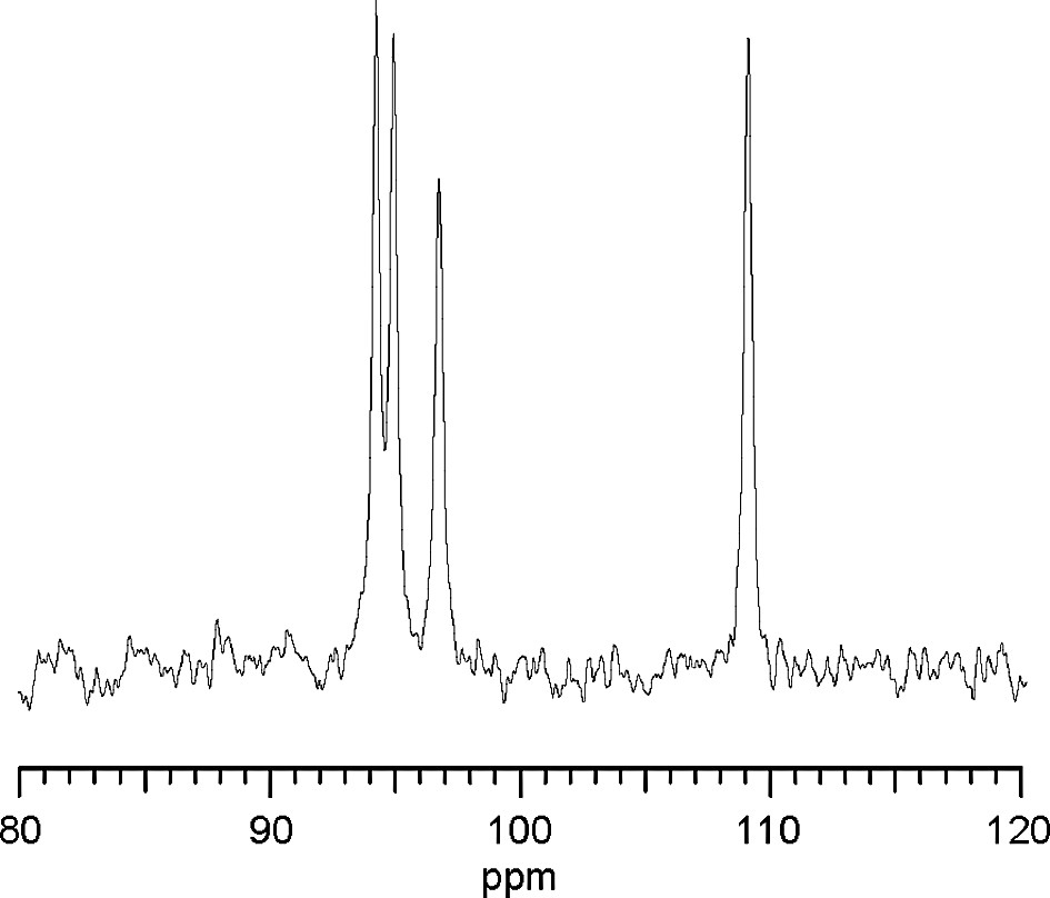
29Si MAS NMR spectrum for CAS-1.
2.4 High-resolution X-ray data collection
High-resolution X-ray powder diffraction data on an untextured sample of CAS-1 were collected on the powder diffractometer on Station B of the Swiss–Norwegian Beamlines (SNBL) at the European Synchrotron Radiation Facility (ESRF) in Grenoble, France. Details of the data collection are given in Table 1.
X-ray data collection
| High resolution | |||
| Synchrotron facility | SNBL (Station B) at ESRF | ||
| Wavelength | 0.79960(2) Å | ||
| Diffraction geometry | Debye–Scherrer | ||
| Analyzer crystal | Si 111 | ||
| Sample | Rotating 1.0 mm capillary | ||
| 2θ Range | 3.5–52.0° | ||
| Step size | 0.002°2θ | ||
| Time per step | 2.6–18.0°2θ | 1.0 s | |
| 18.0–50.0°2θ | 6.0 s | ||
| Textured sample | |||
| Synchrotron facility | SNBL (Station A) at ESRF | ||
| Wavelength | 0.70056 Å | ||
| Standards | Si, zeolite A | ||
| Slit size | 0.4 mm | ||
| Sample-detector distance | 400 mm | 240 mm | |
| dmin | 1.77 Å | 1.16 Å | |
| Time per frame | 120 s | 220 s | |
| Sample rotation per frame | 5° | 5° | |
| Number of frames | 72 | 72 | |
| Non-overlapping reflections | |||
| used to calculate the ODF | 1 2 0 | 0 –3 1 | 0 –1 1 |
| 1 0 0 | 1 –1 1 | 1 –5 1 | |
| 1 –7 1 | 2 –3 1 | 1 4 0 | |
| 1 –3 1 |
Initial attempts to index the diffraction pattern failed, and the presence of an impurity phase was suspected. Laboratory data collected on a second sample (different synthesis batch), in which the impurity phase proved to be dominant, allowed the impurity peaks in the original pattern to be identified, and then the main phase could be indexed on a monoclinic unit cell (a = 24.158 Å, b = 7.016 Å, c = 6.482 Å, β = 95.19°) using the program N-TREOR [9]. A careful examination of the diffraction pattern indicated that the reflections hkl, h + k = 2 n + 1 were systematically absent, so the two most probable space groups could be expected to be C2/m or C2.
2.5 Preparation of a textured sample
To prepare a textured sample (one with a preferential orientation of the crystallites), a sample was mixed with water, disaggregated using ultrasound, and then allowed to settle. The lighter fraction, which remained suspended in water longest, was decanted off and filtered. It was then mixed with a polystyrene/THF solution (ca. two parts sample to one part polystyrene), and the resulting slurry was smeared (along a single direction) onto a glass slide. When the layer had dried, a second layer was applied in the same manner, and this procedure was continued until the sample was thick enough. Finally, a spherical sample with a diameter of ca. 0.3 mm was cut from the CAS-1/polystyrene preparation.
2.6 Collection of X-ray data on the textured sample
Three-dimensional diffraction data were collected on SNBL Station A at the ESRF using the imaging plate setup illustrated in Fig. 3. An imaging plate frame was exposed as the sample was rotated 5° (ψ axis). In all, 72 frames, corresponding to a full 360° rotation of the sample, were exposed with the detector positioned 400 mm from the sample (dmin = 1.77 Å), and then another 72 frames with the detector positioned 240 mm from the sample (dmin = 1.16 Å). The latter were used to access the reflections at higher 2θ, but the resolution in peakwidth is significantly worse at this shorter sample-detector distance. To illustrate the effect of texture on the diffraction pattern, a typical imaging plate frame is shown in Fig. 4. Additional details of the data collection are given in Table 1.
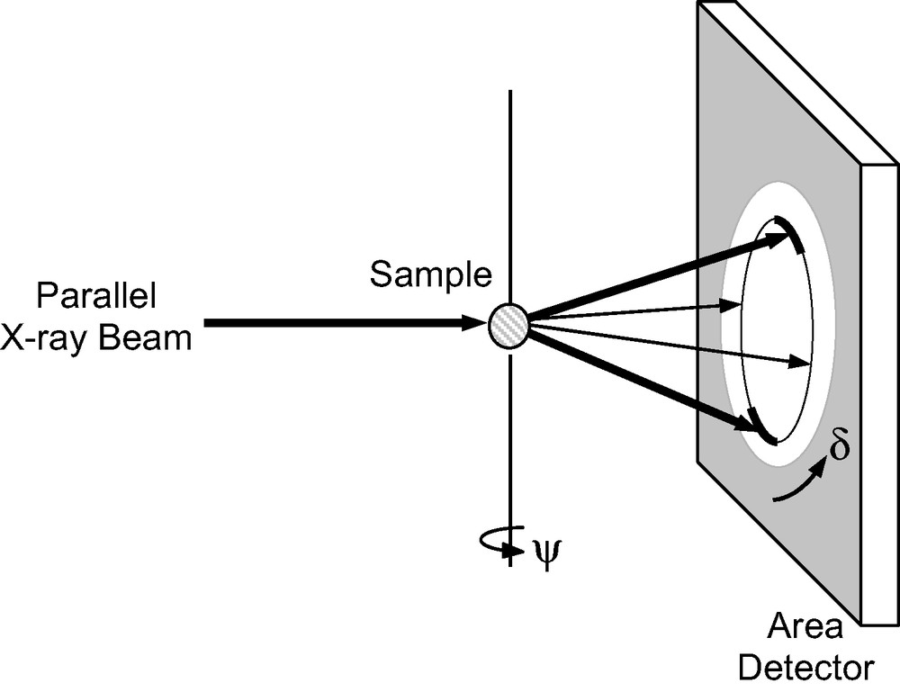
Experimental setup for measurement of a textured sample in transmission mode.
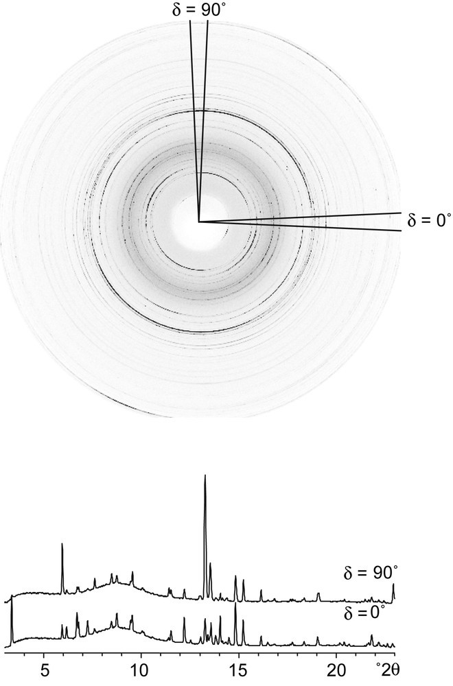
One of the imaging plate frames (ψ = 85°) collected on the textured sample of CAS-1. Note the significant intensity differences around the rings. The diffraction patterns extracted for two of the 72 radial wedges (δ = 0° and 90°) are shown below.
3 Structure determination
3.1 The texture method
Each of the 72 imaging plate frames was divided into 72 radial wedges, corresponding to 5° tilts of the sample (δ), and these in turn were integrated into diffraction patterns using the program Fit2d [10] (see Fig. 4). Only one quadrant of each frame was used for data analysis (others are redundant), so diffraction patterns corresponding to a total of 72 × 18 = 1296 sample orientations {ψ, δ} were generated for each sample-detector distance.
Data analysis is based on the equation
3.2 Application of the texture method to CAS-1
The data collected on the textured CAS-1 sample were treated as described above. It was quickly apparent that the sedimentation treatment of the sample had removed the impurity phase and that the texture was quite pronounced, so data analysis was relatively straightforward. The ODF was determined using 10 non-overlapping reflections (see Fig. 5). Then a single set of intensities was extracted (using the ODF and all patterns simultaneously) and used as input to SHELXS [12] assuming the space group C2/m.
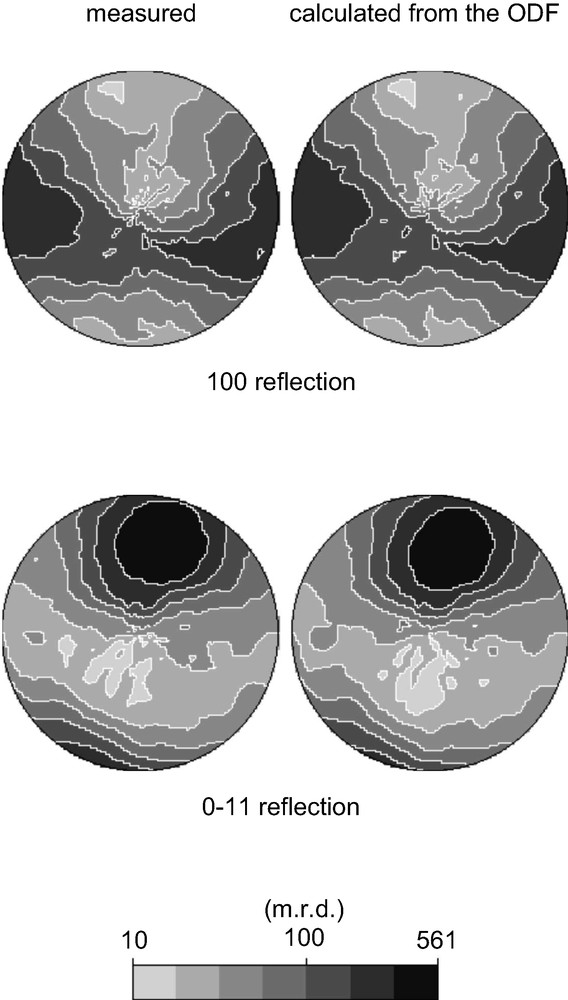
Pole figures for two of the 10 non-overlapping reflections (1 0 0 and 0 –1 1) that were used to calculate the crystallite orientation distribution function (ODF). On the left are the measured data and on the right the pole figure calculated from the ODF. Note that the intensity of each reflection is highly dependent upon the sample orientation (i.e. the position in the pole figure).
A possible solution with four heavy atoms (multiplicities 4, 4, 4 and 8), and seven lighter ones was generated. In view of the chemical analysis and the positions of these atoms, the first heavy atom was assigned as Ca and the other three as Si. However, the 29Si NMR spectrum showed the presence of four Si sites with approximately equal populations, so the symmetry was reduced to C2 and the Si in the site with multiplicity 8 was thereby split into two independent sites of multiplicity 4. The positions of the bridging O atoms were then calculated using the program KRIBER [13].
4 Structure completion and Rietveld refinement
The coordinates from KRIBER were optimized using the program DLS-76 [14], and then used as a starting point for structure completion and Rietveld refinement. For this, the program package XRS-82 [15] was used in conjunction with the high-resolution powder diffraction data collected on an untextured sample. Difference Fourier maps revealed the location of a K+ ion and two water molecules. Both water molecules are coordinated to the K+ ion, and one is also coordinated to the Ca2+ ion. The model is in agreement with the 29Si NMR results, which indicated the presence of three Q3 and one Q4 Si species. The discrepancies in the Si and Na content obtained from chemical analysis and the final structure probably result from the unidentified impurity phase.
A mismatch between the observed and calculated patterns was traced to the presence of some preferred orientation in the sample along the [100] direction (needles aligned along the capillary). Once this factor had been included, refinement proceeded smoothly and converged with the R-values RF = 0.062, Rwp = 0.175, Rexp = 0.097 (Table 2). The final atomic parameters are given in Table 3 and selected distances and angles in Table 4. Estimated standard deviations were taken directly from the Rietveld refinement program and only take into account errors arising from counting statistics [16]. The fit of the profile calculated for this model to the experimental data is shown in Fig. 7. Geometric restraints were imposed on the bond distances and angles of the atoms in the silicate layer. The H atoms of the water molecule were simulated by increasing the occupancy parameter of the associated O atoms from 1 to 1.25. Neutral scattering factors were used for all atoms.
Crystallographic data
| Chemical composition | |(Ca4 K4 (H2O)8| [ Si16 O38] | |
| Unit cell | ||
| a | 24.158(2) Å | |
| b | 7.0160(1) Å | |
| c | 6.4816(4) Å | |
| β (°) | 95.19(8)° | |
| Space Group | C2 | |
| Standard peak for peak shape function (hkl, ˚2θ) | 001, 7.10 | |
| Peak range (number of FWHM) | 20 | |
| Number of observations | 21,409 | |
| Number of contributing reflections | 918 | |
| Number of geometric restraintsa | 47 | |
| Si–O | 1.61(1) Å | 16 |
| O–Si–O | 109.5(2.0)° | 24 |
| Si–O–Si | 145(8)° | 7 |
| Number of profile parameters | 8 | |
| Number of structural parameters | 58 | |
| Preferred orientation vector | [100] | |
| Rexp | 0.097 | |
| Rwp | 0.175 | |
| RF | 0.062 |
a The numbers given in parentheses are the esds assumed for each of the restraints. Each restraint was given a weight equivalent to the reciprocal of its esd.
Positional, thermal and occupancy parameters for CAS-1a
| Atom | x | y | z | Uiso (× 100 Å2) | Occupancyb |
| Ca | 0.2570(1) | 0.0006(7) | 0.9827(2) | 0.88(4) | 4.0 |
| K | 0.1165(1) | –0.0205(6) | 0.2491(2) | 2.62(8) | 4.0 |
| Si(1) | 0.4335(1) | 0c | 0.0100(2) | 0.61(2)d | 4.0 |
| Si(2) | 0.3656(1) | 0.2802(5) | 0.2368(3) | 0.61(2)d | 4.0 |
| Si(3) | 0.3558(1) | –0.0001(6) | 0.5982(2) | 0.61(2)d | 4.0 |
| Si(4) | 0.3670(1) | 0.7200(5) | 0.2447(4) | 0.61(2)d | 4.0 |
| O(1) | 0.5 | –0.0148(10) | 0 | 0.61(2)e | 2.0 |
| O(2) | 0.4039(1) | 0.0334(6) | 0.7816(4) | 0.61(2)e | 4.0 |
| O(3) | 0.3826(1) | 0.4990(5) | 0.2848(5) | 0.61(2)e | 4.0 |
| O(4) | 0.3137(2) | 0.2700(8) | 0.0647(5) | 0.61(2)e | 4.0 |
| O(5) | 0.3519(2) | 0.1887(6) | 0.4544(5) | 0.61(2)e | 4.0 |
| O(6) | 0.4193(2) | 0.1741(4) | 0.1583(5) | 0.61(2)e | 4.0 |
| O(7) | 0.2964(1) | –0.0493(7) | 0.6764(5) | 0.61(2)e | 4.0 |
| O(8) | 0.3059(1) | 0.7442(8) | 0.1294(6) | 0.61(2)e | 4.0 |
| O(9) | 0.3766(2) | 0.8206(6) | 0.4689(5) | 0.61(2)e | 4.0 |
| O(10) | 0.4118(2) | 0.8025(4) | 0.0986(6) | 0.61(2)e | 4.0 |
| Ow(1) | -0.0113(2) | 0.0519(9) | 0.7272(8) | 8.16 | 5.0f |
| Ow(2) | 0.2248(2) | 0.0691(7) | 0.3333(7) | 4.13 | 5.0f |
a Numbers in parentheses are the esd’s in the units of the least significant digit given. Values without an esd were not refined.
b Occupancy parameters are given in terms of atoms per unit cell.
c Fixed to define the zeropoint along the polar b-axis.
d–e Thermal parameters with the same superscript were constrained to be equal.
f Occupancy increased to approximate the electron density of the associated H atoms.
Selected interatomic distances (Å) and angles (°) for CAS-1
| Si(1)–O(1) | 1.62(1) | Ca–O(4) | 2.37(3) |
| –O(2) | 1.60(5) | –O(4') | 2.36(2) |
| –O(6) | 1.61(2) | –O(7) | 2.33(7) |
| –O(10) | 1.62(2) | –O(8) | 2.34(4) |
| –O(8') | 2.36(4) | ||
| Si(2)–O(3) | 1.61(1) | –Ow(2) | 2.51(6) |
| –O(4) | 1.60(7) | ||
| –O(5) | 1.61(2) | K–O(2) | 3.19(1) |
| –O(6) | 1.62(3) | –O(3) | 3.02(1) |
| –O(3′) | 3.47(1) | ||
| Si(3)–O(2) | 1.60(7) | –O(4) | 3.12(1) |
| –O(5) | 1.62(1) | –O(5) | 2.84(1) |
| –O(7) | 1.60(4) | –O(6) | 3.46(1) |
| –O(9) | 1.62(2) | –O(9) | 2.98(1) |
| –O(10) | 3.23(1) | ||
| Si(4)–O(3) | 1.61(1) | –Ow(1) | 2.61(1) |
| –O(8) | 1.60(6) | –Ow(2) | 2.69(1) |
| –O(9) | 1.61(2) | ||
| –O(10) | 1.61(5) | ||
| O–Si(1)–O | Min 108(1) | O–Ca–O (eq) | Min 82(1) |
| Max 110(1) | Max 105(1) | ||
| O–Ca–O (ax) | Min 168(1) | ||
| O–Si(2)–O | Min 106(1) | Max 173(1) | |
| Max 113(1) | |||
| O–Si(3)–O | Min 105(1) | ||
| Max 114(1) | |||
| O–Si(4)–O | Min 105(1) | ||
| Max 115(1) | |||
| Si(1)–O(1)–Si(1) | 173(1) | Ca–O(4)–Ca | 97(1) |
| Si(1)–O(2)–Si(3) | 154(1) | Si(2)–O(4)–Ca | 126(1) |
| Si(2)–O(3)–Si(4) | 146(1) | Si(2)–O(4)–Ca′ | 125(1) |
| Si(2)–O(5)–Si(3) | 146(1) | ||
| Si(1)–O(6)–Si(2) | 139(1) | Ca–O(8)–Ca | 98(1) |
| Si(3)–O(7)–Ca | 134(1) | Si(4)–O(8)–Ca | 134(1) |
| Si(3)–O(9)–Si(4) | 141(1) | Si(4′)–O(8)–Ca | 127(1) |
| Si(1)–O(10)–Si(4) | 141(1) |
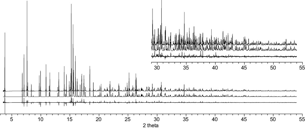
The observed (top), calculated (middle) and difference (bottom) profiles for the Rietveld refinement of CAS-1. To show more detail, the scale for the second half of the pattern has been increased by a factor of 5 in the inset.
5 Discussion
The structure of CAS-1 (Fig. 6a) can be described as a series of silicate double layers (Fig. 6b) connected via chains of edge-sharing CaO5(H2O) octahedra (Fig. 6c). The silicate double layers consist of two 4.82 nets, which are linked to form a two-dimensional eight-ring channel system within the layer. The two nets are related to one another by a twofold axis along the [010]-direction (at O(1)). The negative charge is balanced by K+ ions, which lie in the eight-rings of the 4.82 nets, where they coordinate to one terminal and five bridging oxygens of the silicate layer and to two H2O molecules (Fig. 6d). One of the water molecules is located in the eight-ring channels along the [010] and [001] directions, while the other bridges to a Ca2+ ion in the octahedral chains between the sheets. Because the K+ ions are near the surfaces of the double layer, the two-dimensional channel system contains only water molecules and is not blocked by cations.
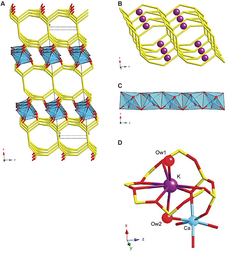
The structure of CAS-1. (A) A simplified representation showing only the silicate double layers (stick representation) and the chains of edge-sharing CaO5(H2O) octahedra (polyhedra), (B) the silicate double layer showing the positions of the K+ ions, (C) the chains of edge-sharing CaO5(H2O) octahedra in more detail, and (D) the coordination spheres of the Ca2+ and the K+ ions.
The structure is related to that of the natural mineral rhodesite [17]. However, there are some important differences between the structures. First, the silicate layers in rhodesite are related by a mirror plane, while those in CAS-1 are related by a twofold axis. Second, the ratios of Si/Ca/K in rhodesite are 8:2:1, whereas those in CAS-1 are 8:2:2. Third, rhodesite is orthorhombic (space group Pmma), while CAS-1 is monoclinic (space group C2). Fourth, the K+ ions in rhodesite are located in the middle of the silicate double layers, where they are coordinated to six bridging oxygens and four water molecules, while in CAS-1, the K+ ions are at the surfaces of the silicate double layers and are coordinated to one terminal and five bridging oxygens and to two water molecules. Finally, there are differences in the environments of the Ca2+ ions. In both structures, the Ca2+ ions are located between the silicate double layers and form chains of edge-sharing octahedra along [010], but in rhodesite, two kinds of Ca2+ ions are present. One is coordinated to six terminal oxygens of the silicate layers, while the other is coordinated to four terminal oxygens and two water molecules. In CAS-1, only one kind of Ca2+ ion is present, and it is coordinated to five terminal oxygens and one water molecule. The Ca2+ ions in the closely related aluminosilicate mineral hydrodelhayelite are similarly coordinated [18].
This structure determination represents the first true test of the texture method using data collected in transmission mode. In particular it shows that the experimental setup is a viable one and that the data analysis software functions properly. Although the structure is not particularly complex, the presence of an impurity phase and the fact that some preferred orientation of the crystallites was present in the ‘untextured’ sample would have complicated structure solution from the high-resolution powder diffraction data alone. With this result, the application of the method to more complex problems can be undertaken with confidence.
Acknowledgements
Experimental assistance from the staff of the Swiss–Norwegian Beamlines at the European Synchrotron Radiation Facility in Grenoble is gratefully acknowledged. This work was supported in part by the Swiss National Science Foundation. J.L.J. thanks the Spanish Secretary of State for Education and Universities and the European Social Funding for their support in the form of a postdoctoral grant.