

1 Introduction
The interest in solid-state organic–inorganic hybrid materials is motivated by their potential applications in such diverse fields as ion exchange [1,2], hydrogen storage [3], magnetism [4,5], luminescence, [6] and catalysis [7]. The attraction lies in combination of vast combinatorial libraries available from the merger of rigid inorganic cluster nuclei with the flexible fine-tunable organic counterparts. What is achieved is a concept that allows for simultaneous predictability and variability. The supramolecular nature of the composites does away with the need for major chemical reactions and this enhances structural predictability. Particular attention has been given to systems based on the octahedral M6X8Y6 and M6X12 clusters that are formed by many of the early transition metals with chalcogens and halogens [8–12] while the organic groups may be chosen to tune connectivity and properties alike [13,14].
The molybdenum (II) chloride cluster ([Mo6Cl8]Cl6)2– has been known since the pioneering crystallographic work of Brosset [15] in 1945. The compound was however described already by Blomstrand [16] in 1859. It was clear from the very first investigations that although several different hydrates form at different pH, all phases retain the same basic structural entity up till neutral pH values. At higher pH values, Mo is reduced to the metal in aqueous solution. Subsequent investigations [3–5] have unravelled the relationships between the structure of the hydrates and the pH of the mother liquor. The cluster is a strong promoter of hydrogen bonding, and the known hydrates all show remarkable water structures. The work presented here is part of a larger effort to understand how this cluster may be used as a structure-directing agent in various media.
2 Experimental
2.1 Synthesis
As starting materials for the syntheses, the acidic hydrate of molybdenum dichloride, [(Mo6Cl8)Cl6](H20O9), henceforth Mo(II)acid, prepared from MoCl5 and elemental Mo as previously decribed [17] was used. All other reagents were from commercial sources used without further purification.
Compound I was synthesised by mixing saturated solutions of Mo(II)acid and guanidinium chloride in DMSO or in FA in the proportions 3:1 by volume. Square platelets of crystallographic quality had precipitated after 24 h at 280 K.
Compound II was prepared by first saturating a solution of 2 parts concentrated HCl and 1 part glacial acetic acid with Mo(II)acid and then mixing this solution in the proportions 3:1 with a saturated solution of C(NH2)3Cl in water. From this mixture, needle-shaped crystals precipitated almost immediately. At room temperature, the aspect ratio of the crystals is quite extreme, but if the crystal growth takes place at 280 K, rhombohedral crystals, more suitable for X-ray investigations, form. Replacing either the HCl/HAc solution of Mo(II)acid or the H2O solution of C(NH2)3Cl or both with the corresponding solutions in EtOH also produced compound II. Replacing C(NH2)3Cl by C(NH2)3NO3 still yielded compound II, and it appears difficult to reduce the Cl content (and hence enhance the condensation) of the product without introducing further counter-ions.
2.2 Structure determination
Single crystal X-ray data were collected on a STOE IPDS with Mo Kα radiation (λ = 0.71073 Å) at 293 K. For both compounds, the atomic positions (Mo and Cl) for the Mo(II)cluster were determined using direct methods using the program Shelxs-97 [18]. All other non-hydrogen atoms were located using difference electron density calculations in the software package JANA2000 [19]. Amine hydrogens were added using geometric constraints on angles (H–N–H = H–N–C = 2π/3) and distances (N-H = 0.9 Å). For compound I, the Laue symmetry was cubic, mm and the systematic absences indicated a F-centered lattice. The space group Fmm and a preliminary model from direct methods refined smoothly to a satisfactory result. For compound II, the Laue symmetry was trigonal m and the systematic extinctions indicated rhombohedral centering and a c-glide perpendicular to [100], although there were a few very weak violations of this condition. A solution in the space group Rc refined to an acceptable R-value, but there was a region around the rotation triad that displayed relatively large residual densities that could be modelled as a centered tetrahedron with centre-to-vertex distances close to those for the C–N bonds in the C(NH2)3+ ion. The most reasonable interpretation was that of a C(NH2)3+ disordered over the three orientations given by the rotation triad. Refining the occupancies of the ‘CN4’ unit corroborated this, giving full occupancy for the N atom sitting on the triad, and 2/3 occupancy for those off this axis. For the C atom on the axis the thermal parameter was large, indicating either partial occupancy, or a true position slightly displaced from the axis, or both. Such a behaviour may be caused by twinning, and reconsidering the weak violations of the c-glides, these may be caused by a lowering of the space group, breaking the three-fold rotational symmetry and preserving the c-glide in one out of three directions. The superposition of the diffraction patterns from individuals with different orientations would then restore the three fold symmetry of the diffraction pattern, and allow for weak violations of the conditions associated with the c-glide extinctions. Transforming the cell, lowering the symmetry to C2/c and treating the structure as a pseudo merohedral twin reduced the R-value and resolved the problem of the strange CN4 unit. It was not possible to allow a full refinement of the guanidinium C atom that tended to retain the position on the former triad unless constrained. Electron density calculations of the final model however show excellent agreement between model and data, and there were no major residual electron densities in the final refinement. It would appear that the close proximity between the three C positions generated by the pseudo-merohedral twinning in conjunction with the perfectly trigonal data set produces a ‘gravity effect’, mergir effect, and the refinement is quite stable. In the final model, it was deemed expedient to use a fully rigid modelng the three positions unless hindered. For the N positions that are more clearly separated, there is no simila for the C(NH2)3+ unit applicable to both the positions on the former hexad and to the other, crystallographically independent guanidinium ion positions. Pertinent crystallographic data are given in Tables 1a and 1b.
[(Mo6Cl8)Cl6]Cl6(C(NH2)3)8 (I)
| Crystal data | Refinement | ||
|
|
|
|
| Data collection | |||
|
|
[(Mo6Cl8)Cl6]Cl3(C(NH2)3)5 (II)
| Crystal data | Refinement | ||
|
|
|
|
| Data collection | |||
|
|
3 Discussion
3.1 Fractional atomic parameters are given in Tables 2 and 3a,3b
For a discussion of the structures it is instructive first to consider the structure of guanidinium chloride, C(NH2)3Cl itself. Here, each guanidinium ion forms strong hydrogen bonds (2.4–2.6 Å) to three surrounding Cl-ions, forming large triangular assemblies. Each Cl-ion, is likewise surrounded by three guanidinium ions and the whole structure is composed of two mutually interpenetrating (10,3) networks (Fig. 1a–1b) separated by a gyroid type surface. Such arrangements have recently been discussed by Lee et al. [20]. A second set of more weakly coordinated Cl-ions may be identified with Cl–H distances ranging from 3.25 Å and up. In structure I, the local arrangement around the guanidinium molecule is identical to that in C(NH2)3Cl, but the connectivity is different, and the triangular units form closed cages that clathrate the octahedral [Mo6Cl14]2– (Fig. 2a–2c) cluster. Again the Cl-H distance is around 2.5 Å. There is no strong direct hydrogen bonding between the C(NH2)3+ ion and the Cl of the cluster unit, the typical closest distances between terminal cluster Cl-ions and guanidinium H start at 3.25 Å. In compound II there are two distinct local geometries for the guanidinium ion. (Fig. 3). Two out of the three symmetrically independent ions adopt the typical configuration of the C(NH2)3Cl structure, forming a slightly puckered layer (a 36 net) together with non-cluster Cl (Fig. 4). The second kind of guanidinium ions connects the layers and couples directly to the octahedral [Mo6Cl14]2– clusters that are situated between the layers. The triangular units are generally much less regular in this compound, and the Cl-H distances range from 2.5 to 3.1 Å for both non-cluster Cl and terminal cluster Cl. A complication that arises is that the generally inert μ3-bonded cluster chlorines exhibit distances around 3.0 Å as well, although these are hardly bonding.
Atomic coordinates and isotropic displacement parameters (in Å2) For (I)
[(Mo6Cl8)Cl6]Cl6(C(NH2)3)8
| Atom | Wyck. | x | y | z | U | |
|
|
|
|
| ||
| Cl3 | 24d | 1/4 | 1/4 | 0 | ||
| C1 | 32f | 0.1583(1) | 0.1583 | 0.1583 | ||
|
|
|
|
| 0.5 | |
| Anisotropic displacement parameters (in Å2) | ||||||
| Atom | U11 | U22 | U33 | U12 | U13 | U23 |
|
|
|
|
|
|
|
| Cl3 | 0.083(2) | 0.083 | 0.041(3) | -0.023)(3) | - | - |
| C1 | 0.071(6) | 0.071 | 0.071 | 0.020(7) | 0.020 | 0.020 |
| N1 | 0.17(3) | 0.059(1) | 0.117(1) | 0.046(8) | 0.09258(2) | 0.042(1) |
Atomic coordinates and isotropic displacement parameters (in Å2) for (II)
[(Mo6Cl8)Cl6]Cl3(C(NH2)3)5
| Atom | Wyck | x | y | z | U |
|
|
|
|
| |
| C2a | 4e | 0.346(1) | 1/2 | 3/4 | 0.0396(7) |
| N21a | 8f | 0.286(1) | 0.5701 | 0.8495 | 0.0570(6) |
| N23a | 4e | 0.468(1) | 1/2 | 3/4 | |
| H21a | 8f | 0.323(1) | 0.6125 | 0.9097 | 0.110(7) |
|
|
|
|
|
Anisotropic displacement parameters (in Å2)
| Atom | U11 | U22 | U33 | U12 | U13 | U23 |
|
|
|
|
|
|
|
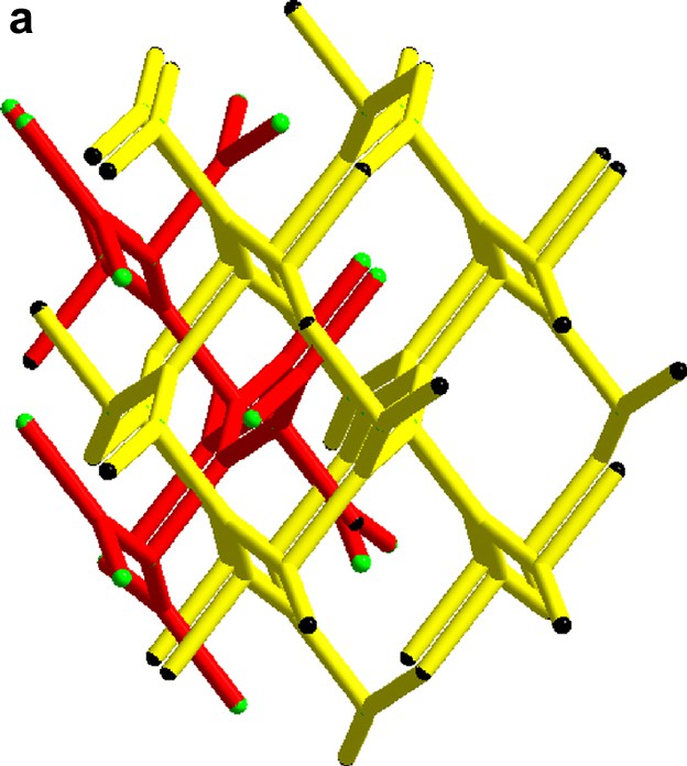
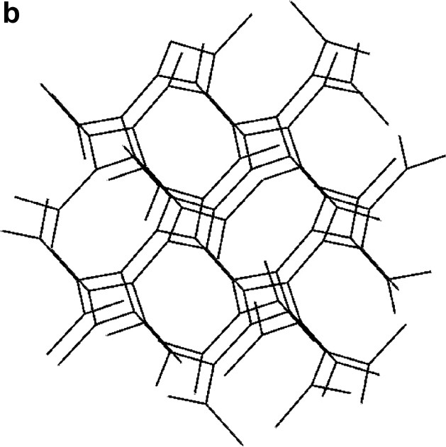
(a) The two interpenetrating (10,3) networks in the guanidinium chloride viewed slightly off the (0 0 1) direction. (b) The single network in the SrSi2 type structure slightly off the (1 0 0) direction.
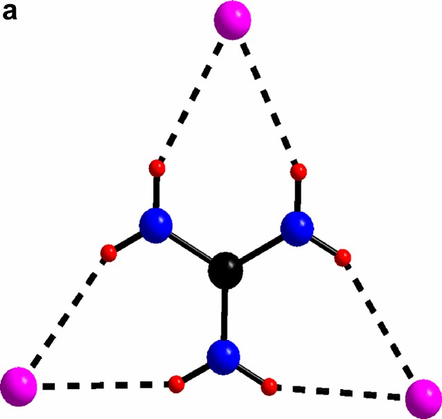
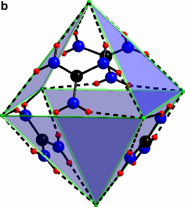
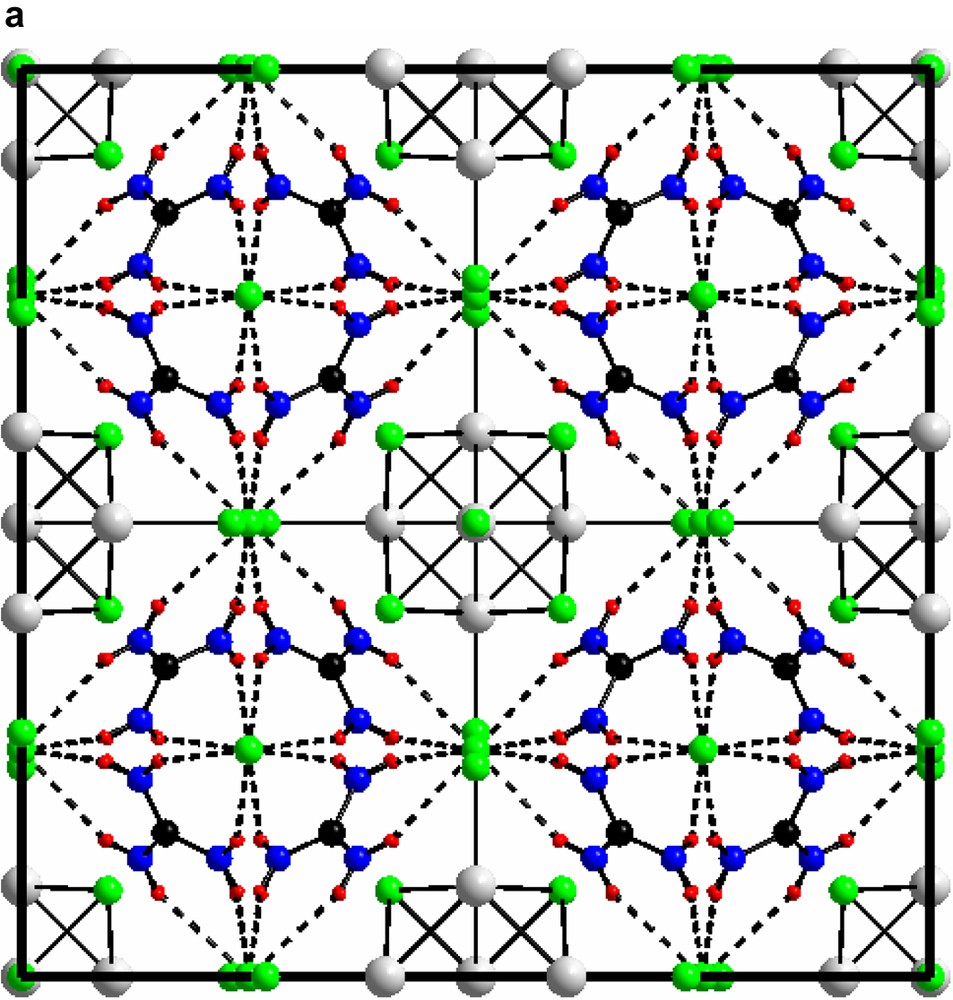
(a) The triangular C(NH2)3+ with its chlorine surrounding in compound I. (b) The guanidinium chloride octahedron, for clarity the triangles without any guanidinium molecules are light blue. c) The triangles in a) form a network via vertex sharing à la ReO3. The Mo(II)-clusters sit in half of the cube-octahedron cavities.

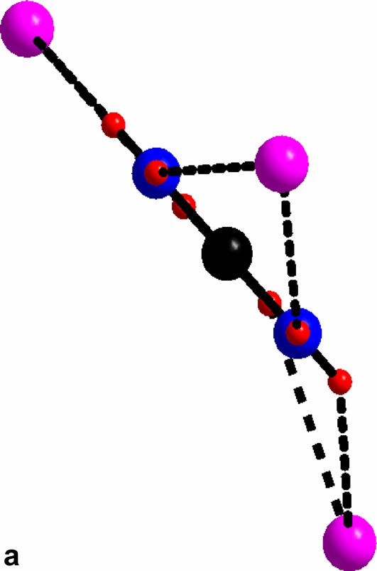

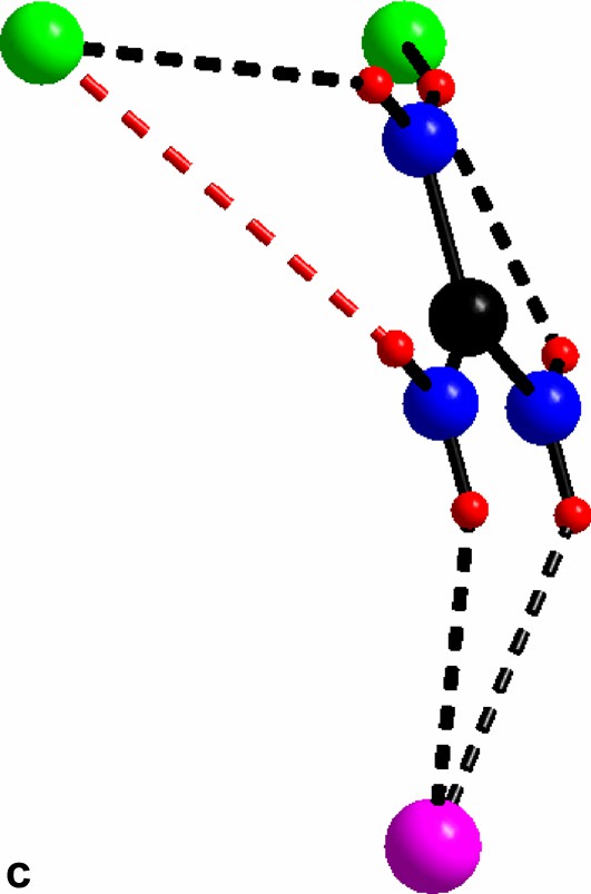
An overview of the guanidinium molecules in compound II. (a) The hydrogen bonded chloride surrounding guanidinium molecule. (b) The hydrogen bonded chloride surrounding guanidinium molecule. (c) The hydrogen bonded chloride surrounding guanidinium molecule; red bond slightly longer (3.34 Å).
For al: green, cluster chloride; purple, free chloride; black, carbon; blue, nitrogen; red, hydrogen.

The slightly puckered layer of guanidinium and free chlorides in compound II.
In both compounds the [Mo6Cl14]2– cluster is encaged in a network formed by guanidinium and non-cluster chloride. In compound I this is very clear-cut, and the direct bonding between the cluster chlorides and the C(NH2)3–Cl network is weak while in compound II direct bonding between the clusters and the latter network is evident. The cages in compound II are all identical. They may be defined by the free chloride ions that form an elongated rhombic dodecahedron (Fig. 5). All these are centered by the [Mo6Cl14]2- clusters. In compound I, in contrast, the C(NH2)3-Cl network forms two different kinds of cages; octahedral and cube-octahedral, in an arrangement reminiscent of the perovskite structure. Here, all the octahedral, and half the cube-octahedral voids are empty, creating a highly porous structure.

The rhombic dodecahedron built up by non cluster Cl- surrounding the Mo(II)- cluster in compound II.
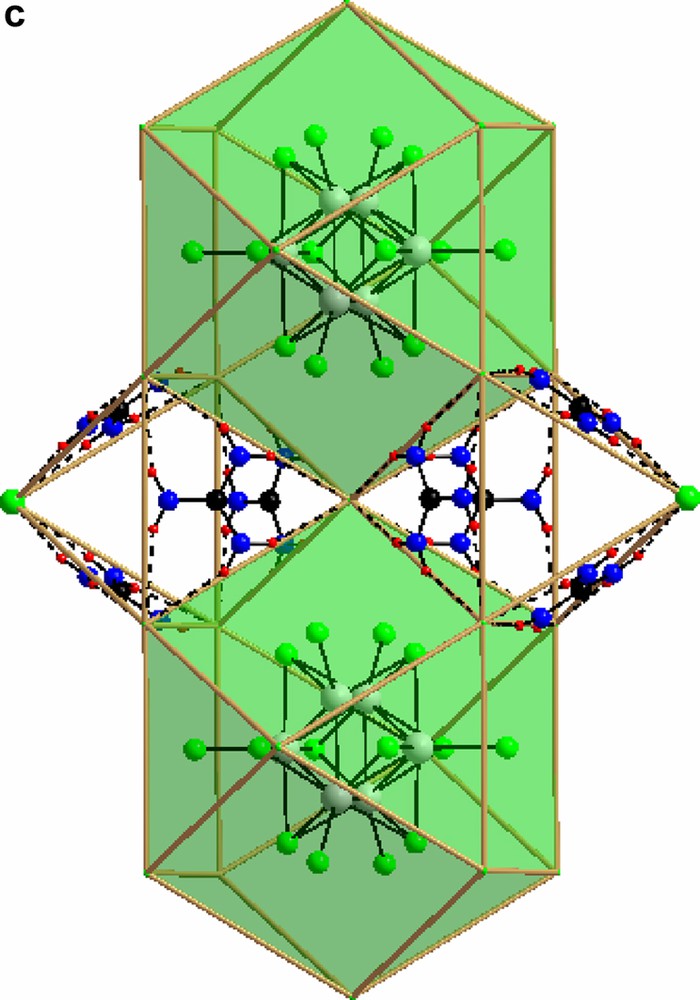
3.2 Unit cell views of compounds I and II are shown in Figs. 6a and 6b
To verify the high porosity of compound I, the density calculated from X-ray data was compared to density measurements with a 0.1 cm3 sample holder in a AccuPyc 1330 pycnometer from Micromeritics. The results from x-ray analysis is 1.8879 g/cm3 and from the pycnometer, 1.9396(9) g/cm3, the difference of 0.0517 g/cm3 in reasonable agreement with the X-ray calculations.
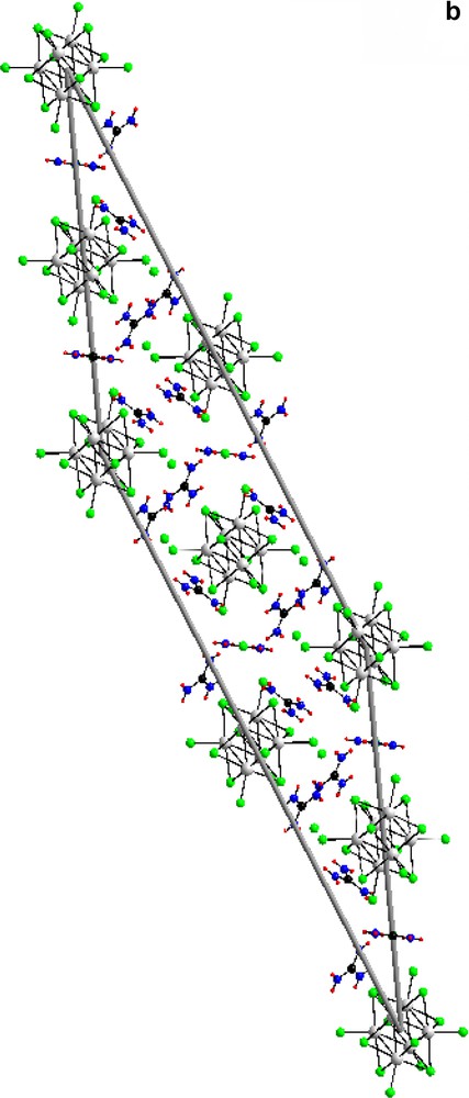
(a) The unit cell of compound (I) [(Mo6Cl8)Cl6]Cl6(C(NH2)3)8 along (1 0 0). (b) The unit cell of compound (II) [(Mo6Cl8)Cl6]Cl3(C(NH2)3)5 along (1 0 0).
For both: green, chloride; grey, molybdenum; black, carbon; blue, nitrogen; red, hydrogen