

1 Introduction
Since the discovery of the first organic metal, namely TTF-TCNQ [1] (TTF = tetrathiafulvalene, TCNQ = tetracyano-p-quinodimethane), TTF and its derivatives have attracted much attention for many years because of their unique π-donor properties and their strong ability to form partially oxidized 1D and 2D materials with unique electronic and magnetic properties [2]. Actually, the large majority of organic metals and superconductors are based on TTF derivatives. In the field of organic conductors, efforts have been devoted to chemical modifications of TTF to develop extended π-systems with an increasing number of sulfur atoms in the periphery in order to reduce the on-site coulombic repulsion and to increase the strength and intermolecular interactions through short S⋯S contacts. This led to the well-known donor bis-ethylenedithio-tetrathiafulvalene (BEDT-TTF). The protected TTF tetrathiolate 2,3,6,7-tetrakis(2-cyanoethylthio)tetrathiafulvalene (TCE-TTF) [3] is well known to be active in the selective protection–deprotection method developed by Becher et al. [4]. It is used as precursors to create new derivatives such as for instance extended molecules [5,6], macrocyclic compounds [7], layered TTF [8], podand-TTFs [9]. TCE-TTF was also used directly to synthesize radical salts [10]. Then we undertook the association of this TCE-TTF molecule with paramagnetic metal cations, followed by a one- pot electro-oxidation with the aim to build conducting-magnetic π–d systems [11]. We report in this paper the synthesis, crystal structures and physical properties of radical cation salts containing fully oxidized TCE-TTF donor, namely (TCE-TTF)X, X = BF4−, CF3SO3−, PF6−.
2 Crystallographic data collection and structure determination
Single crystals of the TCE-TTF salts were mounted on a Nonius four-circle diffractometer equipped with a CCD camera and a graphite monochromated Mo Kα radiation source (λ = 0.71073 Å), from the ‘Centre de diffractométrie’ (CDFIX), ‘Université Rennes-1’, France. Data were collected at 293 K. Structures were solved by direct method using SIR-97 [12] program and refined with full-matrix least squares method on F2 using SHELXL-97 program [13]. Crystallographic data are summarized in Table 1 and ORTEP drawings are given as supplementary materials. The supplementary material has been deposited at the Cambridge Crystallographic Data Centre, 12 Union Road, Cambridge CB2 1EZ, UY (CCDC 662344–662348). Though the syntheses were performed in the same way, the five resulting compounds are not isostructural. Since the three salts contain the same donor molecule, the same labeling scheme was used for all compounds (see Fig. 1); for the centrosymmetric organic part, the labeling scheme corresponds to the left part of the drawing. In this paper, an intermolecular short contact corresponds to a distance shorter than the sum of the corresponding van der Waals (vdW) radii. The stoichiometries of the salts as well as the central C3–C4 bond lengths prove that TTF molecules are fully oxidized; they are carrying a entire (+1) positive charge.
Crystal data and structure refinement of TCE-TTF salts
| Compound | BF4 | CF3SO3 | PF6 | ||
| Phase a | Phase b | Phase a | Phase b | ||
| Empirical formula | C18H16BF4N4S8 | C18H16BF4N4S8 | C19H16F3N4O3S9 | C18H16F6N4PS8 | C18H16F6N4PS8 |
| Formula weight | 631.69 | 631.64 | 693.90 | 689.80 | 689.80 |
| Temperature (K) | 293(2) | 293(2) | 293(2) | 293(2) | 293(2) |
| Wavelength (Å) | 0.71073 | 0.71073 | 0.71073 | 0.71073 | 0.71073 |
| Crystal system | Monoclinic | Monoclinic | Monoclinic | Triclinic | Monoclinic |
| Space group | C2/c | C2/c | P21/n | P-1 | P21/c |
| a (Å) | 29.8345(5) | 19.624(1) | 12.6679(3) | 5.5504(4) | 10.688(1) |
| b (Å) | 9.4427(2) | 5.479(1) | 12.7734(4) | 9.9279(7) | 5.687(1) |
| c (Å) | 22.6071(5) | 24.604(1) | 18.7170(6) | 13.2585(10) | 22.686(1) |
| α (°) | 90 | 90 | 90 | 73.150(3) | 90 |
| β (°) | 122.958(1) | 102.15(1) | 106.597(1) | 81.314(3) | 100.34(1) |
| γ (°) | 90 | 90 | 90 | 75.621(3) | 90 |
| Volume (Å3) | 5343.89 | 2586.2(5) | 2902.46(15) | 674.86(8) | 1356.5(3) |
| Z | 8 | 4 | 4 | 1 | 2 |
| Calcd density (g cm−3) | 1.570 | 1.622 | 1.588 | 1.697 | 1.689 |
| Absorption coefficient (mm−1) | 0.713 | 0.737 | 0.737 | 0.781 | 0.777 |
| F(000) | 2568 | 1284 | 1412 | 349 | 698 |
| Crystal size (mm3) | 0.24 × 0.10 × 0.10 | 0.50 × 0.50 × 0.20 | 0.18 × 0.03 × 0.03 | 0.25 × 0.10 × 0.10 | |
| θ range for data collection | 5.21°, 27.49° | 2.12°, 25.68° | 2.28°, 26.34° | 2.20°, 27.64° | 1.82°, 27.49° |
| Index ranges | −38 ≤ h ≤ 38 | −23 ≤ h ≤ 23 | −15 ≤ h ≤ 15 | −7 ≤ h ≤ 7 | −13 ≤ h ≤ 13 |
| −12 ≤ k ≤ 11 | −6 ≤ k ≤ 6 | −15 ≤ k ≤ 14 | −12 ≤ k ≤ 12 | −7 ≤ k ≤ 6 | |
| −29 ≤ l ≤ 29 | −29 ≤ l ≤ 29 | −23 ≤ l ≤ 23 | −17 ≤ l ≤ 17 | −29 ≤ l ≤ 29 | |
| Reflections collected | 11,541 | 4629 | 10,045 | 5184 | 5695 |
| Ind. reflections [R(int)] | 6096 [0.0398] | 2460 [0.0389] | 5903 [0.0387] | 3101 [0.0470] | 3120 [0.0309] |
| Completeness to theta max (%) | 99.2 | 99.8 | 99.8 | 98.7 | 99.8 |
| Absorption correction | Semi-empirical from equivalents | ||||
| Max. and min. transmission | 0.9321, 0.8475 | 0.8666, 0.7095 | 0.9770, 0.8722 | 0.9263, 0.8294 | |
| Refinement method | Full-matrix least-squares on F2 | ||||
| Data/restraints/parameters | 6096/0/316 | 2461/0/159 | 5903/0/372 | 3101/0/169 | 3120/0/169 |
| Goodness-of-fit on F2 | 1.017 | 1.063 | 1.021 | 1.001 | 1.129 |
| Final R indices [I > 2σ(I)] | |||||
| R1 | 0.0471 | 0.0540 | 0.0542 [3421] | 0.0761 | 0.733 |
| wR2 | 0.1046 | 0.1415 | 0.1299 | 0.1915 | 0.2250 |
| R indices (all data) | |||||
| R1 | 0.0854 | 0.0831 | 0.1078 | 0.1211 | 0.1018 |
| wR2 | 0.1235 | 0.1605 | 0.1617 | 0.2257 | 0.2587 |
| Largest diff. peak and hole (e Å−3) | 0.416, −0.337 | 1.113, −0.512 | 0.304, −0.328 | 1.007, −0.492 | 0.764, −0.845 |

Molecular structure of organic part in [TCE-TTF](BF4) phase a, with labeling scheme used for all compounds.
2.1 Compound (1): [TCE-TTF](BF4)
This compound crystallizes as two different monoclinic phases both in the C2/c space group. The unit-cell volume of the b-phase is twice the volume of the a-phase. The conformation of the organic parts, as well as of their respective packing, are totally different. All the bond lengths observed onto the organic molecule are in the same range in the two phases, except the nitrile bond lengths which are shorter in the a-phase compared to the b-phase (see Tables 2 and 3).
Selected bond lengths [Å] and angles [°] for a-phase of BF4 salt
| C3–C4 | 1.397(4) | C1–S1 | 1.743(4) | C13–C14 | 1.527(5) |
| C3–S3 | 1.718(3) | C6–S8 | 1.736(3) | C8–C9 | 1.444(6) |
| C4–S6 | 1.716(3) | C2–S2 | 1.752(3) | C17–C18 | 1.460(5) |
| C3–S4 | 1.719(3) | C5–S7 | 1.749(3) | C11–C12 | 1.448(6) |
| C4–S5 | 1.715(3) | C7–S1 | 1.807(5) | C14–C15 | 1.454(6) |
| C1–S3 | 1.727(3) | C16–S8 | 1.802(3) | C9–N1 | 1.129(6) |
| C6–S6 | 1.735(3) | C10–S2 | 1.783(4) | C18–N4 | 1.129(5) |
| C2–S4 | 1.750(4) | C13–S7 | 1.832(4) | C12–N2 | 1.127(5) |
| C5–S5 | 1.727(3) | C7–C8 | 1.514(6) | C15–N3 | 1.124(5) |
| C1–C2 | 1.357(5) | C16–C17 | 1.530(4) | ||
| C5–C6 | 1.366(4) | C10–C11 | 1.505(6) | ||
| C2–C1–S3 | 116.3(3) | C3–C4–S6 | 123.6(2) | C8–C7–S1 | 114.2(3) |
| C2–C1–S1 | 125.0(3) | C3–C4–S5 | 120.6(2) | C9–C8–C7 | 111.2(4) |
| S3–C1–S1 | 118.5(2) | S6–C4–S5 | 115.77(17) | N1–C9–C8 | 177.0(6) |
| C1–C2–S4 | 116.7(3) | C6–C5–S5 | 116.3(2) | C11–C10–S2 | 117.2(3) |
| C1–C2–S2 | 124.4(3) | C6–C5–S7 | 125.1(2) | C12–C11–C10 | 115.7(4) |
| S4–C2–S2 | 118.6(2) | S5–C5–S7 | 118.67(17) | N2–C12–C11 | 179.0(5) |
| C4–C3–S3 | 119.3(2) | C5–C6–S6 | 116.5(2) | C14–C13–S7 | 114.5(2) |
| C4–C3–S4 | 125.0(2) | C5–C6–S8 | 121.6(2) | C15–C14–C13 | 113.2(3) |
| S3–C3–S4 | 115.63(17) | S6–C6–S8 | 121.84(17) | N3–C15–C14 | 179.0(5) |
| C17–C16–S8 | 112.8(2) | C2–S2–C10 | 102.91(17) | C4–S6–C6 | 95.23(14) |
| C18–C17–C16 | 108.9(3) | C3–S3–C1 | 96.03(16) | C5–S7–C13 | 98.98(16) |
| N4–C18–C17 | 176.7(4) | C3–S4–C2 | 95.03(16) | C6–S8–C16 | 103.26(14) |
| C1–S1–C7 | 102.20(18) | C4–S5–C5 | 95.45(14) |
Selected bond lengths [Å] and angles [°] for the b-phase of BF4 salt
| C3–C3i | 1.390(8) | C1–S1 | 1.745(4) | C8–C9 | 1.463(8) |
| C3–S3 | 1.725(4) | C2–S2 | 1.754(4) | C11–C12 | 1.458(7) |
| C3–S4 | 1.716(4) | C7–S1 | 1.804(5) | C9–N1 | 1.145(7) |
| C1–S3 | 1.738(4) | C10–S2 | 1.811(5) | C12–N2 | 1.134(6) |
| C2–S4 | 1.741(4) | C7–C8 | 1.530(7) | ||
| C1–C2 | 1.358(6) | C10–C11 | 1.519(7) | ||
| C2–C1–S3 | 116.4(3) | S4–C3–S3 | 115.4(2) | N2–C12–C11 | 179.7(7) |
| C2–C1–S1 | 121.8(3) | C3i –C3–S3 | 121.2(4) | C1–S1–C7 | 104.3(2) |
| S3–C1–S1 | 121.8(2) | C8–C7–S1 | 115.6(3) | C2–S2–C10 | 101.0(2) |
| C1–C2–S4 | 116.5(3) | C9–C8–C7 | 112.5(4) | C3–S3–C1 | 95.84(19) |
| C1–C2–S2 | 125.6(3) | N1–C9–C8 | 179.8(6) | C3–S4–C2 | 95.8(2) |
| S4–C2–S2 | 117.9(2) | C11–C10–S2 | 115.3(4) | ||
| C3i –C3–S4 | 123.4(4) | C12–C11–C10 | 113.6(4) |
2.1.1 Phase a
The asymmetric unit is built up from one molecule of TCE-TTF and one BF4− anion, both lying in general positions. The four nitrile arms of the molecule lie onto the same side of the plane formed by the TTF skeleton (cis type).
The shortest intermolecular contacts involving non-hydrogen atoms take place between the sulfur atoms belonging to two TTF molecules (S3⋯S6 = 3.235(1) Å) which yield a centrosymmetrical dimer with the second intradimer S⋯S contact involving the sulfur atoms of the TTF skeleton equal to S4⋯S5 = 3.407(1) Å (Fig. 2). Taking into account the four nitrogen atoms from nitrile groups, we can notice that one contact involving a non-hydrogen atom with a distance shorter than the sum of the corresponding vdW values is observed along the b axis (N4⋯S6 = 3.166(4) Å). Furthermore, the shortest distance involving non-hydrogen atoms between the organic moieties and the anion are observed between sulfur atoms of the TTF skeleton and fluorine (S6⋯F3 = 3.114(3) Å; S3⋯F2 = 3.260(3) Å) which are also developed along the b axis. According to these contacts, the packing can be described as mixed organic/inorganic layers in the bc plane. Adjacent dimers along the b axis direction are parallel, whereas the angle between the mean plane of two adjacent dimers along the c axis is found equal to 39.94(2)°.

Shortest intermolecular contacts in the a-phase of the BF4 salt. (For interpretation of the references to color in this figure, the reader is referred to the web version of this article.)
The third dimension of the solid is realized thanks to a contact in the vdW range which takes place between two adjacent mixed planes, N2⋯C17 = 3.248(6) Å.
2.1.2 Phase b
The asymmetric unit is built up from a half molecule in special position; the half TTF fragment is near centers of inversion while the boron atom of the BF4− anion is lying on a two-fold axis. The two cyanoethylene arms of the donor asymmetric unit lie onto the same side of the plane formed by the TTF skeleton. Due to the center of symmetry of the donor molecule, two nitrile groups in TCE-TTF are located on the same molecular plane; the two remaining cyanoethylene groups are located under the molecular plane (trans type). Fig. 3 shows the packing of the crystal structure. It corresponds to an organic layer of dithio tetrathiofulvalene (DT-TTF) skeleton packed in the ab plane which alternates along c axis with layers built with the anion and the nitrile fragments of donor molecule. DT-TTF mean planes are parallel in one layer, while those of two organic molecules belonging to adjacent layers form an angle of 84.99(4)°. Short contacts exist within a layer as well as between layers. The nitrogen atom N2 of a nitrile group yields one organic layer thanks to two contacts: one of them corresponds to the shortest intermolecular distance involving non-hydrogen atoms, it takes place between N2 and one sulfur atom of the TTF skeleton (N2⋯S3 = 3.142(5) Å). Thanks to the center of symmetry of the molecule, these short intermolecular contacts lead infinite chains along the a + b direction. In this molecule, the same nitrogen atom N2 interacts with a sulfur atom of another molecule, yielding infinite chain along the a − b direction (N2⋯S2 = 3.285(6) Å); one can notice that two adjacent molecules which interact via N2⋯S2 contacts are coplanar in the layer. The other intermolecular contact involving non-hydrogen atom takes place between nitrogen atom N1 and the sulfur atom of the cyanoethylsulfanyl group of a molecule from the adjacent layer (N1⋯S1 = 3.158(5) Å). Thanks to these contacts, molecules form infinite chains along a − b direction, in which the mean planes of two adjacent molecules forms an angle of 84.99(4)°.

View of the unit cell of b-phase of BF4 salt in the bc plane. (For interpretation of the references to color in this figure, the reader is referred to the web version of this article.)
2.2 [TCE-TTF](CF3SO3)
The structure of TCE-TTF in [TCE-TTF](CF3SO3) is shown in Fig. 4 and selected bond distances and angles are given in Table 4. The asymmetric unit contains one donor molecule and one triflate anion, meaning that the donor molecule is fully oxidized. In the donor molecule, the four cyanoethylthio arms are folded down in the same side of the TTF mean plane (cis type). Disorder exists in one of the four cyanoethyl groups, the arm bearing the N3 atom is disordered in two positions C16A–C17A–C18A and C16B–C17B–C18B, with occupancy factors of 0.55(2) and 0.45(2), respectively, and the terminal N4 position is fully occupied.

Molecular structure of the organic part in [TCE-TTF](CF3SO3), with labeling scheme.
Selected bond lengths [Å] and angles [°] for [TCE-TTF](SO3CF3) salt
| C3–C4 | 1.388(6) | C6–S8 | 1.757(4) | C13–C14 | 1.531(8) |
| C3–S3 | 1.713(4) | C2–S2 | 1.749(4) | C8–C9 | 1.438(8) |
| C4–S6 | 1.714(4) | C5–S7 | 1.742(5) | C17A–C18A | 1.41(4) |
| C3–S4 | 1.713(4) | C7–S1 | 1.811(5) | C17B–C18B | 1.57(3) |
| C4–S5 | 1.721(4) | C16A–S8 | 1.772(18) | C11–C12 | 1.459(8) |
| C1–S3 | 1.736(4) | C16B–S8 | 1.84(2) | C14–C15 | 1.425(11) |
| C6–S6 | 1.720(5) | C10–S2 | 1.798(5) | C9–N1 | 1.124(7) |
| C2–S4 | 1.726(4) | C13–S7 | 1.796(6) | C18A–N4 | 1.21(3) |
| C5–S5 | 1.747(4) | C7–C8 | 1.520(7) | C18B–N4 | 1.04(2) |
| C1–C2 | 1.366(6) | C16A–C17A | 1.65(4) | C12–N2 | 1.140(7) |
| C5–C6 | 1.366(6) | C16B–C17B | 1.57(4) | C15–N3 | 1.126(11) |
| C1–S1 | 1.738(4) | C10–C11 | 1.519(6) | ||
| C2–C1–S3 | 116.0(3) | C1–C2–S2 | 125.1(3) | S4–C3–S3 | 115.5(2) |
| C2–C1–S1 | 123.8(3) | S4–C2–S2 | 118.4(2) | C3–C4–S6 | 122.5(3) |
| S3–C1–S1 | 120.2(2) | C4–C3–S4 | 122.3(3) | C3–C4–S5 | 122.1(3) |
| C1–C2–S4 | 116.4(3) | C4–C3–S3 | 122.2(3) | S6–C4–S5 | 115.3(2) |
| C6–C5–S7 | 125.4(3) | C12–C11–C10 | 112.6(4) | N4–C18B–C17B | 160(4) |
| C6–C5–S5 | 115.2(3) | N2–C12–C11 | 177.6(6) | C1–S1–C7 | 101.7(2) |
| S7–C5–S5 | 119.3(3) | C14–C13–S7 | 113.2(4) | C2–S2–C10 | 100.8(2) |
| C5–C6–S6 | 117.4(3) | C15–C14–C13 | 116.6(6) | C3–S3–C1 | 95.6(2) |
| C5–C6–S8 | 124.9(4) | N3–C15–C14 | 177.4(9) | C3–S4–C2 | 95.7(2) |
| S6–C6–S8 | 117.7(3) | C17A–C16A–S8 | 102.8(12) | C4–S5–C5 | 95.8(2) |
| C8–C7–S1 | 114.3(3) | C18A–C17A–C16A | 105(3) | C4–S6–C6 | 95.8(2) |
| C9–C8–C7 | 114.0(4) | N4–C18A–C17A | 156(4) | C5–S7–C13 | 102.2(2) |
| N1–C9–C8 | 179.4(7) | C17B–C16B–S8 | 109.1(14) | C6–S8–C16A | 100.4(4) |
| C11–C10–S2 | 112.2(3) | C16B–C17B–C18B | 99.6(19) | C6–S8–C16B | 98.0(5) |
Two organic molecules form centrosymmetrical dimer with short S⋯S contacts (S3⋯S6 = 3.326(2) Å and S4⋯S5 = 3.331(2) Å). Interdimer contacts shorter than the sum of the corresponding vdW radii are observed between nitrogen atoms of two nitrile groups and sulfur atoms of the TTF skeleton. Two molecules from two dimers are packed together thanks to centrosymmetrical interactions: N4 and S4 of one molecule interact with S4 and N4 of the other molecule, respectively (S4⋯N4 = 3.321(7) Å). The second shortest S⋯N contact of 3.291(7) Å takes place between N3 and S3, to yield zig-zag chains along b axis, the angle between the TTF mean plane of adjacent molecule is 70.37(2)°.
The four nitrile arms of this dimer form a cage in which the triflate anion lies with short distances between the central carbon atoms and two of the three oxygen atoms (C3⋯O1 = 3.105(2) Å). The fluorine atom F3 of this triflate anion is also close to the sulfur atom on one nitrile arm, S1⋯F3 = 3.150(4) Å belonging to another molecule. Two molecules linked to the triflate anion show an angle of 70.41(2)° between their respective TTF mean planes (Fig. 5).

View of the unit cell of CF3SO3 salt with shortest intermolecular contacts. (For interpretation of the references to color in this figure, the reader is referred to the web version of this article.)
2.3 [TCE-TTF](PF6)
This compound crystallizes as two different phases; the a-phase in a triclinic system, whereas the b-phase crystallizes in a monoclinic system. Selected bond distances and angles are given in Tables 5 and 6 for a-phase and b-phase, respectively.
Bond lengths [Å] and angles [°] for phase a of PF6 salt
| C3–C3ii | 1.403(9) | C1–S1 | 1.759(5) | C8–C9 | 1.470(9) |
| C3–S3 | 1.717(5) | C2–S2 | 1.748(5) | C11–C12 | 1.441(8) |
| C3–S4 | 1.719(5) | C7–S1 | 1.820(6) | C9–N1 | 1.117(8) |
| C1–S3 | 1.744(5) | C10–S2 | 1.818(6) | C12–N2 | 1.149(8) |
| C2–S4 | 1.734(5) | C7–C8 | 1.513(8) | ||
| C1–C2 | 1.355(7) | C10–C11 | 1.527(8) | ||
| C2–C1–S3 | 116.6(4) | C1–C2–S4 | 116.6(4) | C3ii –C3–S3 | 123.0(5) |
| C2–C1–S1 | 125.7(4) | C1–C2–S2 | 122.1(4) | C3ii–C3–S4 | 121.1(5) |
| S3–C1–S1 | 117.6(3) | S4–C2–S2 | 120.9(3) | S3–C3–S4 | 115.9(3) |
| C8–C7–S1 | 115.1(4) | C12–C11–C10 | 112.7(5) | C3–S3–C1 | 95.3(2) |
| C9–C8–C7 | 112.7(5) | N2–C12–C11 | 177.2(7) | C3–S4–C2 | 95.6(2) |
| N1–C9–C8 | 179.0(7) | C1–S1–C7 | 100.8(2) | ||
| C11–C10–S2 | 112.6(4) | C2–S2–C10 | 103.8(2) |
Bond lengths [Å] and angles [°] for phase b of [TCE-TTF](PF6)
| C3–C3iii | 1.391(9) | C1–S1 | 1.749(5) | C8–C9 | 1.470(8) |
| C3–S3 | 1.720(5) | C2–S2 | 1.737(5) | C11–C12 | 1.448(10) |
| C3–S4 | 1.721(5) | C7–S1 | 1.800(6) | C9–N1 | 1.148(8) |
| C1–S3 | 1.731(5) | C10–S2 | 1.801(6) | C12–N2 | 1.143(9) |
| C2–S4 | 1.747(5) | C7–C8 | 1.513(8) | ||
| C1–C2 | 1.356(7) | C10–C11 | 1.523(9) | ||
| C2–C1–S3 | 117.1(4) | C3iii–C3–S4 | 122.8(5) | N2–C12–C11 | 178.4(8) |
| C2–C1–S1 | 122.8(4) | S3–C3–S4 | 115.6(3) | C1–S1–C7 | 102.5(2) |
| S3–C1–S1 | 119.9(3) | C8–C7–S1 | 116.1(4) | C2–S2–C10 | 103.2(2) |
| C1–C2–S2 | 123.0(4) | C9–C8–C7 | 113.5(5) | C3–S3–C1 | 95.6(2) |
| C1–C2–S4 | 116.0(4) | N1–C9–C8 | 179.3(7) | C3–S4–C2 | 95.6(2) |
| S2–C2–S4 | 120.3(3) | C11–C10–S2 | 112.7(4) | ||
| C3iii–C3–S3 | 121.6(5) | C12–C11–C10 | 112.0(5) |
2.3.1 Phase a
The structure of [TCE-TTF](PF6) phase a is shown in Fig. 6. The asymmetric unit is built up from half molecules of donor and of anion lying in an inversion center. The two nitrile arms of the donor asymmetric unit lie onto the same side of the plane formed by the TTF skeleton, leading to a trans-type molecule.

View along b axis with shortest intermolecular distances in phase b of [TCE-TTF](PF6). (For interpretation of the references to color in this figure, the reader is referred to the web version of this article.)
Organic molecules are packed together, giving rise to an organic layer in the ab plane, in which the TTF skeleton defined as mean planes are parallel. This plane alternates with anionic layers along the c axis. All nitrogen atoms of nitrile arms have short contacts with sulfur atoms of organic molecule in the ab plane. The contact between N1 and S4 is the shortest yielding chains along the b axis (N1⋯S4 = 3.119(6) Å). The nitrile arm bearing the N2 atom interacts with the S2 sulfur atom of the neighboring molecule along the a axis (S2⋯N2i = 3.139(6) Å). The interplanar distance between the mean planes of the two closest TTF molecules packed along a axis is 3.459 Å.
2.3.2 Phase b
This compound is isostructural with [TCE-TTF](SbF6) [14]. The monoclinic unit cell contains two fully oxidized centrosymmetric TCE-TTF molecules with cyanoethyl groups in trans position and two PF6− units.
TCE-TTF are packed as infinite non-dimerized chains along the b axis; the TTF mean plane forms an angle of 54.14° with the ac plane, 35.87° with the ab plane and 82.58° with the bc plane. The mean plane distance between two TTF fragments in the chain is 3.331(4) Å, but due to the angle between the chain axis and the TTF mean plane, two adjacent TTF are shifted, the shortest distance between two molecules takes place between C1⋯S4 and C2⋯S3 (3.514(5) and 3.567(5) Å), respectively, no short S⋯S contacts are observed (see Fig. 7). TTF columns and PF6 anions alternated along the a direction, whereas no alternation is observed in the c direction, where the TTF mean planes of two neighboring chains form an angle of 71.6(2)°. Fig. 8 shows the two short intermolecular contacts involving non-hydrogen atoms. Both take place between F2 fluorine atom of PF6 and two TCE-TTF molecules of the same column. The first contact is observed in the TTF molecular plane between PF6 and a TTF: F2⋯S3 = 3.174(5) Å, the second one is observed between the same PF6 anion and the TTF: C7⋯F2 = 3.077(7) Å.

View of the non-dimerized chains along the b axis with shortest intermolecular distances. (For interpretation of the references to color in this figure, the reader is referred to the web version of this article.)

Shortest intermolecular contacts along a axis. (For interpretation of the references to color in this figure, the reader is referred to the web version of this article.)
3 Physical measurements
3.1 Electrical measurements
All materials are built up from fully oxidized donor's molecules; electrical measurements revealed that all compounds are insulators.
3.2 Magnetic measurements of [TCE-TTF](PF6) phase a
The magnetization of powdered sample of [TCE-TTF](PF6) phase a has been studied in the 1.8–200 K temperature range. The thermal dependences of χM and χMT, χM being the molar magnetic susceptibility and T the temperature in Kelvin, are represented in Fig. 9.

Thermal variations of χM and χMT of powdered sample of [TCE-TTF](PF6) phase a: (○) experimental points, (—) best fitted curves (see text).
At 200 K χMT is equal to 0.345 cm3 K mol−1, close to the expected value for isolated s = 1/2 spins with a Zeeman factor equal to 2.00. On cooling, χMT remains constant down to 50 K, temperature below which it decreases more and more rapidly. According to the crystal structure, the oxidized TCE-TTF cations are packed in the a direction to form chains of equally spaced s = 1/2 radicals. The spin Hamiltonian in zero field is the magnetic susceptibility for negative J values (antiferromagnetic interactions) is expressed as follows for s = 1/2, taking into account the presence of paramagnetic impurities [15]:
4 Experimental
4.1 General experimental
Reactions were carried out under argon atmosphere, using dry dioxygen-free solvents. Commercial starting materials were used as purchased.
4.2 Synthesis of 2,3,6,7-tetrakis(2-cyanoethylthio)tetrathiafulvalene
The synthesis of 2,3,6,7-tetrakis(2-cyanoethylthio)tetrathiafulvalene was performed with modifications according to Ref. [3] by cross-coupling of 4,5-bis(2-cyanoethylthio)-1,3-dithiole-2-thione (1) and 4,5-bis(2-cyanoethylthio)-1,3-dithiole-2-one (2) (see Fig 10).
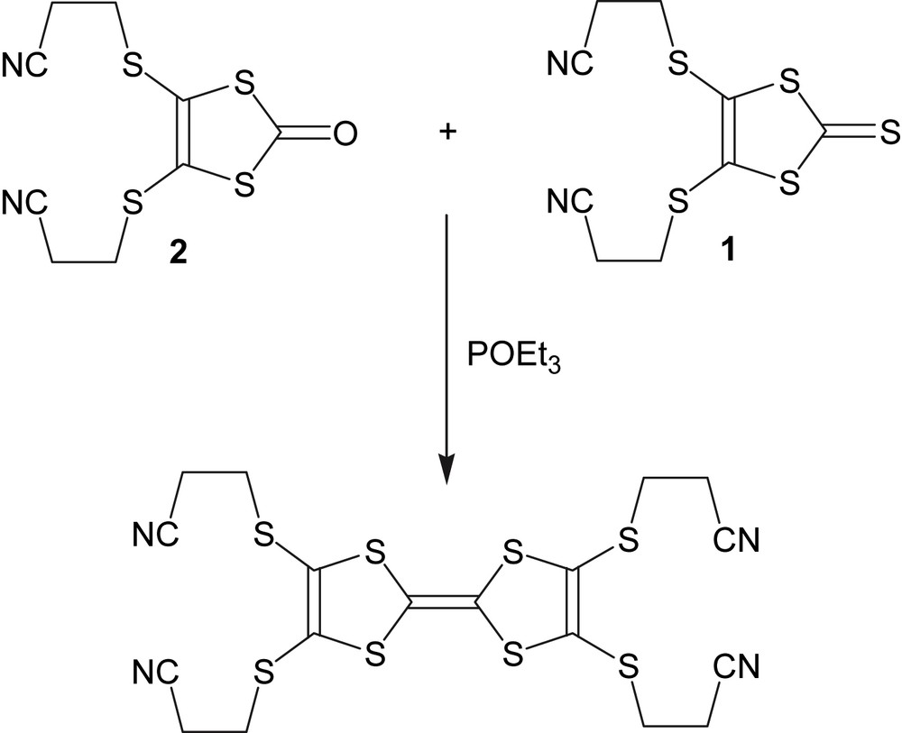
Cross-coupling scheme.
4,5-Bis(2-cyanoethylthio)-1,3-dithiole-2-thione (1, 1.6 g, 5.2 mmol) and 4,5-bis(2-cyanoethylthio)-1,3-dithiole-2-one (2, 1.0 g, 3.5 mmol) was suspended in 150 mL of toluene. After adding 10 mL of freshly distilled triethylphosphite to the mixture, the solution was refluxed at 120 °C for 2 h and left at room temperature overnight. After the addition of 100 mL of diethyl ether, the solution was filtered and the filtrate washed with diethyl ether. Large orange crystals (1.47 g, yield: 78%) were obtained.
4.3 General procedure for 2,3,6,7-tetrakis(2-cyanoethylthio)tetrathiafulvalene crystals
The title compounds were obtained by electrocrystallization on a platinum wire electrode (∅ = 1 mm) by anodic oxidation of the organic donor TCE-TTF in the presence of copper hexafluoroacetylacetonate and a tetrabutylammonium salt of the corresponding anion in a glass U-cell with two 15 mL compartments separated with a glass frit. All the solvents were distillated under argon before use.
4.4 Synthesis of BF4, CF3SO3 and PF6 salts
Copper hexafluoroacetylacetonate (30 mg, 0.06 mmol) and TCE-TTF (10 mg, 0.02 mmol) were added in the anodic compartment under argon flux. Under argon flux, 60 mg of solid tetrabutylammonium salt (BF4−, CF3SO3− and PF6−) and a mixture of 10 mL of toluene–dichloromethane (3:1) were added in both compartments. Phases b were obtained when benzene is used instead of toluene. After applying a constant current of 0.5 μA, crystals appeared and were left to grow for about one week. The colors and shapes of the materials are different. [TCE-TTF](BF4) crystallized as green thin plates for phase a and dark red plates for b-phase and dark red cubes were obtained for [TCE-TTF](CF3SO3). [TCE-TTF](PF6) crystallized as black needles and dark plates for phases a and b, respectively.
5 Conclusion
The cross-coupling of 4,5-bis(2-cyanoethylthio)-1,3-dithiole-2-thione and 4,5-bis(2-cyanoethylthio)-1,3-dithiole-2-one increased slightly the yield of the target protected TTF donor. This donor yields five new radical cation salts which were characterized by X-ray crystal structure analysis. This study shows that TCE-TTF molecule is very flexible, as it crystallizes with various conformations. Due to the complete oxidation of the donors, all compounds are insulators. Magnetic measurements performed on the phase a of [TCE-TTF](PF6) revealed an antiferromagnetic behavior. One of our goals with this molecule is to synthesize materials with electronic conductivity; we are still working to grow crystalline materials with partially oxidized TCE-TTF donors.