

1 Introduction
The renewed interest in Fischer–Tropsch (FT) synthesis is primarily due to its use in the conversion of natural gas to more valuable long-chained hydrocarbons and new strict legislation about residual sulfur and aromatics in hydrocarbon fuels [1–5]. In FT synthesis, long chain hydrocarbons are typically produced on cobalt supported catalysts which are prepared via impregnation with cobalt nitrate and promoters [5]. After different thermal treatments, the catalysts undergo activation which results in the cobalt metal phase. It has been shown that the FT reaction occurs on cobalt metal particles. Cobalt catalysts supported on alumina and promoted with noble metals (Pt, Ru, Re) are among the most efficient catalysts for FT synthesis [5–8].
In the industry, the low-temperature FT synthesis [9,10] is performed in multi-tubular fixed bed reactors and slurry bubble column reactors. The catalysts in these reactors are typically used in the form of grains and pellets, whose size can vary from 50 μm to several millimeters. Hydrocarbon yield is sensitive to the mass transfer into the reactor as well as inside the catalyst grains.
The catalytic activity in FT synthesis is a function of the number of cobalt surface sites. A higher density of cobalt metal sites usually results in a better catalytic performance [2,3]. Recently, we have shown [11–14] that cobalt particle size in FT supported catalysts prepared via aqueous impregnation is strongly affected by the catalyst pore diameter. Even in catalysts with high cobalt contents (up to 35 wt.%) the presence of narrow pores enhances cobalt dispersion [13]. Thus, in the catalysts with high cobalt content, cobalt loadings on the one hand, should not much affect cobalt dispersion and on the other hand, it should increase the absolute number of cobalt active sites. Thus, the catalysts with higher cobalt content would be generally more active for FT synthesis than their lower loaded cobalt counterparts prepared using the same impregnation procedure and support.
Though the absolute number of cobalt active sites is an important parameter of FT catalysts, the uniform repartition of active phase between the catalyst grains (intergranular repartition) is also essential in attaining the maximal and enduring hydrocarbon productivity. The non-uniform intergranular distribution of the cobalt active phase in a fixed bed reactor would lead to heat spots in the catalyst bed, affect hydrocarbon selectivity and consequently result in a more rapid deactivation. In addition to the intergranular repartition, the repartition of the active phase inside the catalyst grain (intragranular repartition) could also have an impact on the catalyst performance and, in particular, hydrocarbon selectivity. Slower diffusion of carbon monoxide relative to hydrogen would affect the H2/CO ratio inside the catalyst grains and thus would lead to a higher selectivity for lighter hydrocarbons [2,15].
The conditions of catalyst preparation would normally have influence on both intergranular and intragranular cobalt repartitions in supported FT catalysts. It can be expected that uniform intergranular and intragranular cobalt repartitions are much easier to achieve in the catalyst with lower cobalt content. Very little information is available about the repartition of active phase in cobalt supported FT catalysts with high cobalt contents prepared via conventional incipient wetness impregnation.
Scanning electron microscopy (SEM) is an efficient tool for the investigation of catalyst morphology at the range from 1 μm to 1 mm. In combination with energy-dispersive X-ray spectroscopy (EDX), SEM can provide both qualitative and quantitative information about the repartition of different chemical elements in the catalyst matrix.
The present paper focuses on the intergranular and intragranular cobalt repartitions in alumina supported Pt-promoted FT catalysts with a wide range of cobalt content (10–25 wt.%). The structure of cobalt catalysts at nano-scale and micron-scale range was investigated by several characterization techniques. The SEM–EDX was used to evaluate the distribution of cobalt between the catalyst grains and inside a catalyst grain. The performance of the catalyst with high cobalt content was evaluated in a fixed bed microreactor.
2 Experimental
Cobalt catalysts (Table 1) were synthesized via incipient wetness co-impregnation using aqueous solutions of cobalt nitrate (Co(NO3)2·6H2O) and tetramine platinum nitrate (Pt(NH3)4(NO3)2). Commercial Puralox SCCA-5/170 alumina manufactured by Sasol with SBET = 165 m2/g, pore diameter of 8.3 nm and total pore volume of 0.477 cm3/g was used as a catalytic support. The catalysts with cobalt content of 10 wt.%, 12.5 wt.% or 15 wt.% and platinum content of 0.05 wt.% were prepared in a single impregnation step. The catalysts with higher cobalt contents (20 wt.% and 25 wt.%) were prepared in two impregnation steps. The second impregnation was performed with the calcined catalysts containing 10 wt.% and 12.5 wt.% of cobalt. During the second impregnation, the platinum promoter was added to obtain 0.1 wt.% of Pt in the final catalysts. The impregnated solids were dried and calcined in a flow of air at 573 K. After calcination, the samples were sieved to remove catalyst particles smaller than 50 μm. Cobalt content in the catalysts was measured by atomic absorption at the “Service central d'analyse du CNRS” (Vernaison, France). The elementary analysis data are in good agreement with the expected or nominal values. The catalysts are labeled as xCo–yPt/Al2O3 where x and y designate, respectively, the weight content of cobalt and platinum.
Characterization of cobalt supported catalysts.
| Catalyst | Pretreatment | Total pore volume (cm3 g−1) | BET surface area (m2 g−1) | Average pore diameter (nm) | Size of Co3O4 crystallites by XRD (nm) |
| Al2O3 | As received | 0.477 | 165 | 8.3 | – |
| 10Co–0.05Pt/Al2O3 | Dried | 0.308 | 129 | 7.0 | – |
| Calcined | 0.381 | 141 | 7.9 | 8.2 | |
| 12.5Co–0.05Pt/Al2O3 | Dried | 0.283 | 119 | 6.9 | – |
| Calcined | 0.362 | 142 | 7.9 | 8.7 | |
| 15Co–0.05Pt/Al2O3 | Dried | 0.210 | 87 | 7.1 | – |
| Calcined | 0.337 | 135 | 7.7 | 9.9 | |
| 20Co–0.1Pt/Al2O3 | Dried | 0.273 | 115 | 7.5 | – |
| Calcined | 0.306 | 119 | 8.1 | 11.2 | |
| 25Co–0.1Pt/Al2O3 | Dried | 0.206 | 84 | 7.4 | – |
| Calcined | 0.281 | 115 | 8.0 | 11.4 |
Specific surface areas and porosity of the oxidized catalysts were measured by low-temperature nitrogen adsorption using the BET method (Table 1). X-ray powder diffraction measurements were conducted using a Siemens D5000 diffractometer using Cu (Kα) radiation. The temperature programmed reduction (TPR) was carried out in an AutoChem II 2920 (Micromeritics) using 0.1 g of the sample in 5 vol.% H2/Ar stream. The temperature ramping rate was 5 °C/min. The particle size distributions in the support and catalysts were measured using L230 Beckman-Coulter laser granulometer. The morphological and microchemical analyses were performed with a Philips SEM 505 scanning electron microscope equipped with an EDX Philips 505 microprobe at 5 and 20 keV. SEM images were obtained from secondary electrons. The analyses are performed on the riddled catalysts (50 μm ≤ particle sizes ≤ 250 μm). The catalytic performance was evaluated in a fixed bed microreactor at 20 bars and 220 °C.
3 Results and discussion
3.1 Catalyst structure at the nano-scale range
The BET surface area, total pore volume and average pore diameter of the support and dried and calcined catalysts are presented in Table 1. Impregnation of the catalysts with cobalt nitrate, followed by drying, results in a significant drop in both BET surface area and pore volume, while the pore diameter is not affected. Note that the impregnated and dried catalysts contain significant concentrations of undecomposed cobalt nitrate. Catalyst calcination leads to an increase in BET surface area and pore volume (Table 1). This suggests that cobalt nitrate introduced on impregnation is preferentially located inside the pores of alumina and it decomposes during the calcination.
The surface area and pore volume of the calcined catalysts were nevertheless slightly smaller than for the original support and gradually decrease with cobalt content (Table 1). This decrease can be due to the dilution of the support with cobalt and partial plugging of catalyst pores with cobalt species. Interestingly, the pore diameter of cobalt catalysts does not vary as a function of cobalt content.
The XRD patterns of calcined cobalt catalysts are shown in Fig. 1. They exhibit the peaks characteristic of γ-alumina and Co3O4. The calculations using the Scherrer equation [16] and 511 (2θ = 59.5°) Co3O4 diffraction lines yield crystallites' sizes about 8–12 nm. Note that cobalt particle size is comparable with the pore size of alumina supported catalysts. Moreover, the crystallite size of cobalt oxide does not much vary with overall cobalt loading in the range from 10 to 25 wt.%. Previously, similar results [11–13] were obtained for cobalt silica supported catalysts. This seems to indicate that cobalt dispersion in cobalt alumina supported catalysts is principally affected by the support texture.
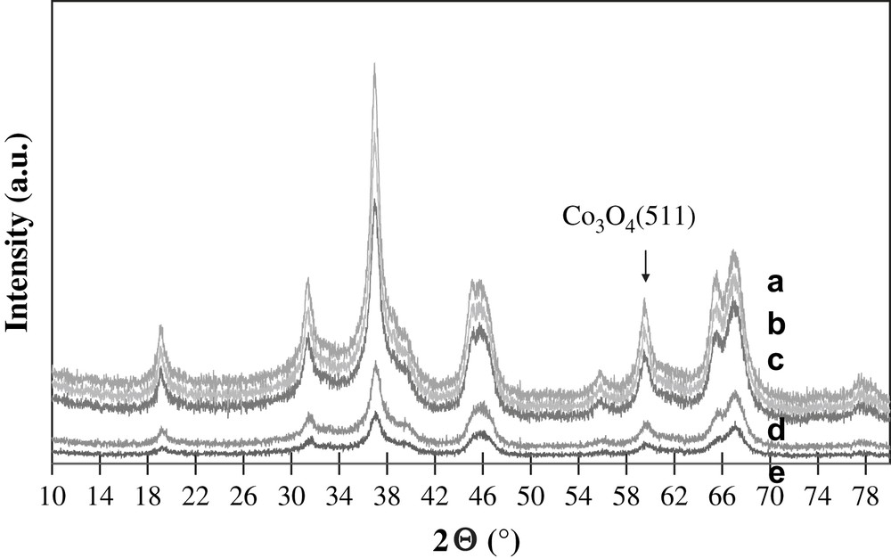
XRD patterns of a) 25Co–0.1Pt/Al2O3, b) 20Co–0.5Pt/Al2O3, c) 15Co–0.5Pt/Al2O3, d) 12.5Co–0.05Pt/Al2O3, e) 10Co–0.05Pt/Al2O3.
A large number of reports have addressed the reduction of cobalt catalysts [17–28]. Fig. 2 shows the experimental TPR profiles of the calcined catalysts with different cobalt content. The profiles are similar; they are constituted by two groups of peaks. It is known that reduction of Co3O4 proceeds via intermediate formation of CoO:
| Co3O4 → CoO → metallic Co. |
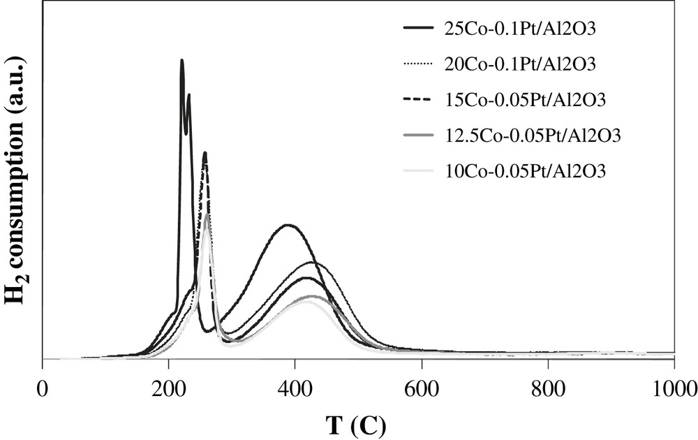
H2-TPR profiles of calcined catalysts.
According to the literature data, it is unlikely that the presence of two peaks of cobalt reduction could be assigned to bimodal particle size distribution and higher water concentration in smaller catalyst pores (d < 4 nm) [19,29]. Indeed, the BJH pore size distribution in the catalysts has a single narrow maximum at 7–8 nm.
It was shown that the position of TPR peaks for the reduction of Co3O4 into CoO and then into metallic cobalt depends on the support, size of cobalt particles and operating conditions (use of pure or diluted hydrogen, space velocity, temperature ramp…) In agreement with previous data [17–21] the low-temperature peaks at 180–300 °C seem to be attributed to a partial reduction of Co3O4 to CoO, while the peaks observed at 300–550 °C are assigned to the reduction of CoO to metallic cobalt. This attribution is consistent with the interpretation of TPR peaks of cobalt alumina supported catalysts performed using in situ magnetic method [8,30] which is selectively sensitive to the presence of cobalt metal ferromagnetic phases.
Note that the low-temperature TPR peaks exhibit doublets (25Co–0.1Pt/Al2O3) and shoulders. The presence of doublets and shoulders can be due to the presence of residual cobalt nitrate [8] or CoO(OH) species as suggested by van de Loosdrecht et al. [31,32]. TPR experiments coupled with simultaneous detection of the products by mass spectroscopy have revealed the emission of significant amounts of nitrogen. Nitrogen emission coincides with the appearance of shoulders and doublets in TPR profiles at 180–230 °C. This suggests that some of the low-temperature TPR peaks could be attributed to reductive decomposition of residual cobalt nitrate in diluted hydrogen. No TPR peaks are observed at a temperature higher than 550 °C. This indicates the high extent of cobalt reduction and suggests that barely reducible cobalt aluminate compounds have not formed in the cobalt alumina supported catalysts promoted with platinum.
Thus, the characterization data suggest that at the micron-scale level, small Co3O4 particles of 9–12 nm seem to be the dominant cobalt species in calcined Pt-promoted cobalt alumina catalysts with cobalt loading from 10 to 25 wt.%. The size of these cobalt oxide particles does not vary with cobalt loading. No cobalt aluminate species which are reducible at temperatures higher than 750 °C were detected in the catalysts from TPR data.
3.2 Morphology and cobalt repartitions in the catalysts at the micron-scale range
3.2.1 Catalyst morphology
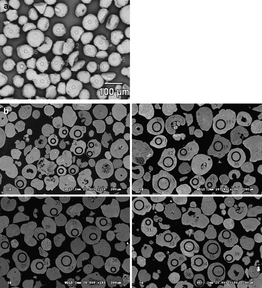
The particle size distribution curves evaluated using laser granulometry at the micron-scale range for the alumina support and 25Co–0.1Pt/Al2O3 catalyst are shown in Fig. 3. The particle size distribution curves are almost identical. They indicate that both the support and catalyst with higher cobalt content (25Co–0.1Pt/Al2O3) are constituted by the grains with the average diameter of about 90 μm. This suggests that impregnation with cobalt nitrate, drying and calcination do not modify the shape of particle distribution curves and thus, the catalyst granulometry is comparable with that of the original support. The SEM results are consistent with the granulometric data. The SEM–EDX images of the catalysts with different cobalt contents (Fig. 4) display polydispersed spherical particles with average diameter of about a 100 μm. The porous structure of several grains was analyzed using microtomy. It was found (Fig. 5) that several catalyst grains exhibited noticeable defects of porosity such as macropores and cavities.
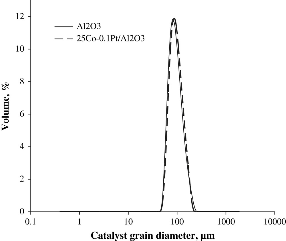
Catalyst particle size distribution in alumina and 25Co–0.1Pt/Al2O3 catalyst measured by laser granulometry.
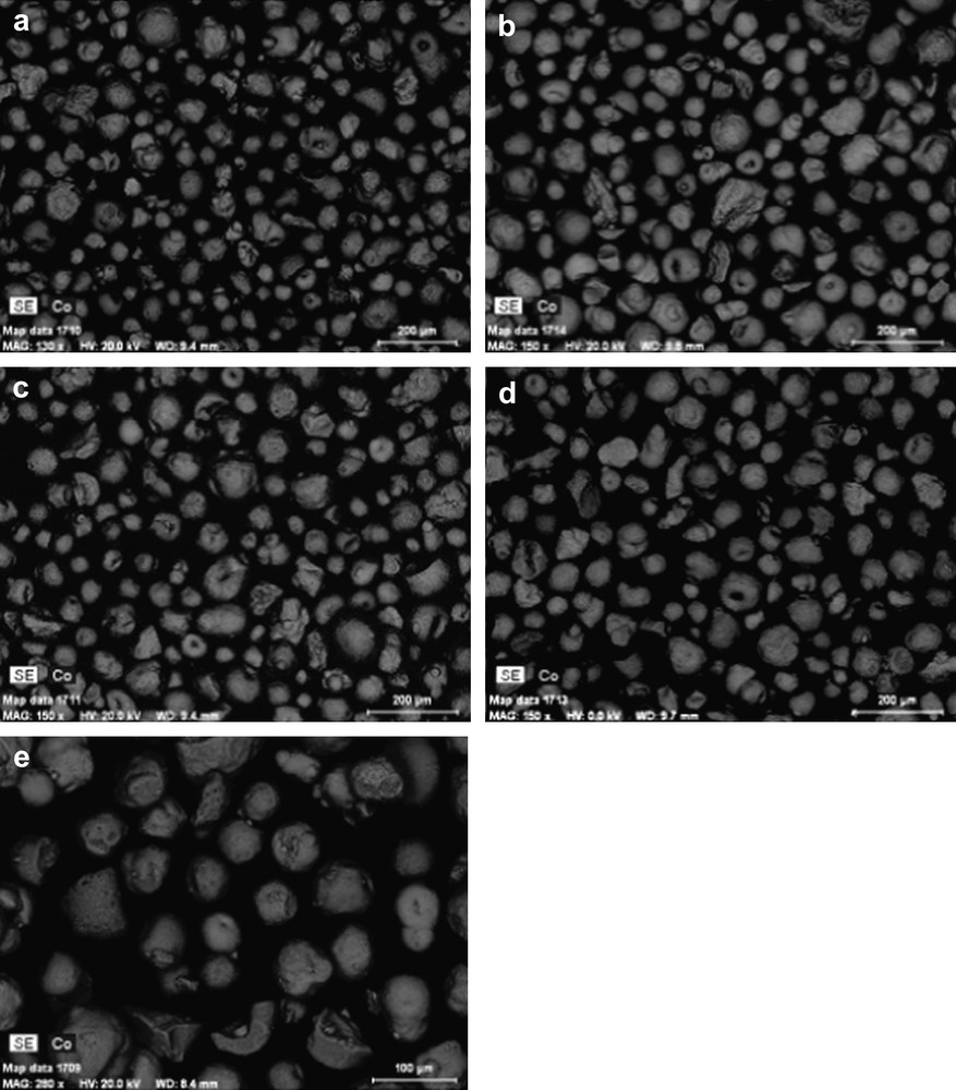
SEM micrographs: a) 10Co–0.05Pt/Al2O3, b) 12.5Co–0.05Pt/Al2O3, c) 15Co–0.5Pt/Al2O3, d) 20Co–0.5Pt/Al2O3, e) 25Co–0.1Pt/Al2O3.
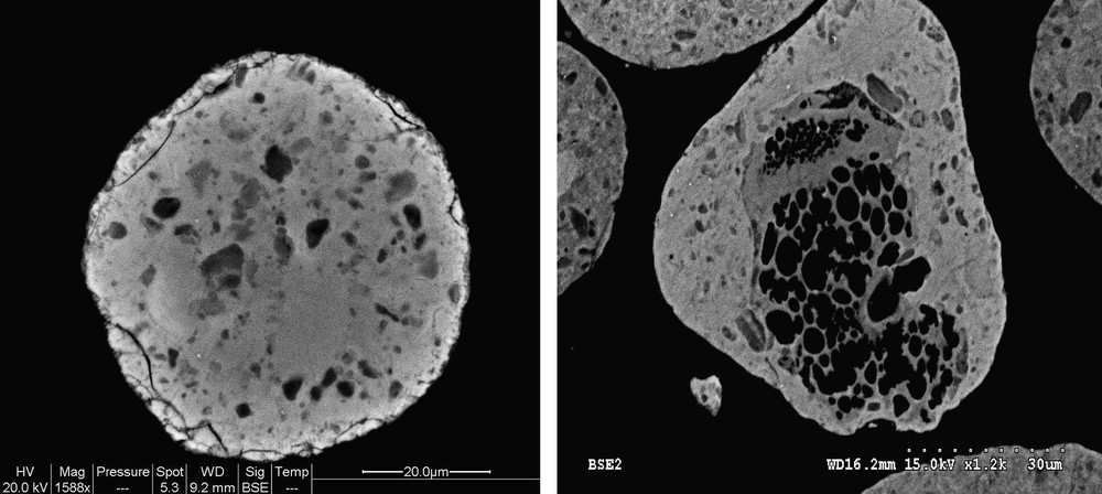
SEM images showing the defects of porosity in 25Co–0.1Pt/Al2O3 catalyst.
3.2.2 Cobalt repartitions
In addition to the information about catalyst morphology, Fig. 4 also displays cobalt mapping obtained using EDX. The cobalt is shown with grey color. Cobalt repartition appears qualitatively uniform in all the catalysts. Because of the electric charges accumulated in the particles and particle roughness, cobalt repartition could not be evaluated quantitatively from SEM–EDX images of catalyst grains without any pretreatment (Fig. 4). Thus to analyze cobalt repartition in cobalt catalysts in a more quantitative manner, the samples for SEM–EDX measurements were prepared using microtomy: the catalyst grains were included in a resin, polished and coated with gold. The relevant SEM–EDX images obtained for the catalyst with high cobalt content (25Co–0.1Pt/Al2O3) are shown in Fig. 6, while the results of EDX microanalysis are displayed in Fig. 7. The average cobalt content in the catalyst was calculated from cobalt content measured by EDX in the spots (Fig. 6) using the following formula:
SEM images of 25Co–0.1Pt/Al2O3 a) on powder, without preliminary preparation, b) on polishing slide after coating with gold.
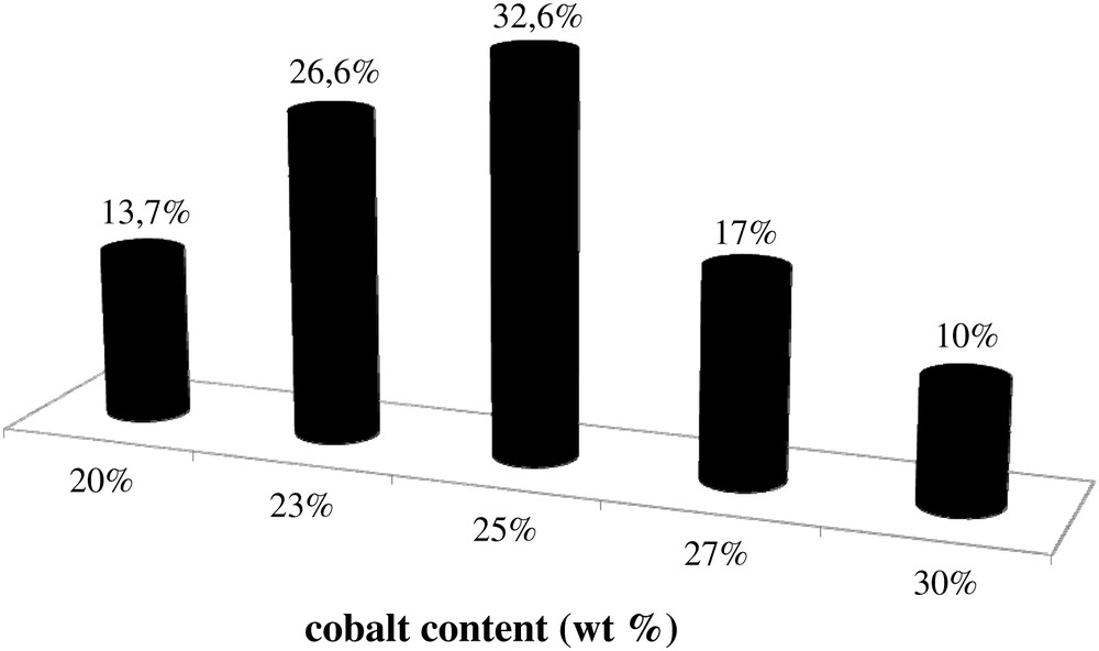
Histogram of cobalt repartition in 25Co–0.1Pt/Al2O3 catalyst.
SEM–EDX analysis was also used to evaluate cobalt repartition in a single catalyst grain in the samples with lower (12.5Co–0.05Pt/Al2O3) and higher cobalt contents (25Co–0.1Pt/Al2O3). The relevant SEM images are shown in Fig. 8. Analysis of chemical composition using EDX in several spots in a single grain of 12.5Co–0.05Pt/Al2O3 catalyst gives the average cobalt content of 13.3 wt.% with deviations smaller than 1 wt.%. With 25Co–0.1Pt/Al2O3, EDX yields the 23.8 and 22.3% cobalt weight contents for the spot shown in Fig. 8. Similar results were obtained with other grains of 12.5Co–0.05Pt/Al2O3 and 25Co–0.1Pt/Al2O3 catalysts.

SEM–EDX analysis of a single catalyst grain: a) 12.5Co–0.05Pt/Al2O3, b) 25Co–0.1Pt/Al2O3.
To complete the study, cobalt concentration was measured through a grain of 25Co–0.1Pt/Al2O3 catalyst prepared by microtomy. The results are shown in Fig. 9. The cobalt content varies only very slightly inside the grain of the catalyst. The cobalt repartition seems therefore to be also uniform.
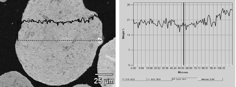
Cobalt concentration profile through a grain of 25Co–0.1Pt/Al2O3 catalyst.
The cobalt alumina supported catalysts were evaluated in FT synthesis using a fixed bed microreactor. The C5+ productivity for 25Co–0.1Pt–Al2O3 catalyst at 220 °C and 20 bars of syngas pressure (H2/CO = 2) was 0.52 g/h gcat with 6% methane selectivity. The catalytic performance of the synthesized cobalt catalysts was consistent with available literature data [7,31,33,34].
4 Conclusion
The structure of a series of cobalt alumina supported FT catalysts with a wide range of cobalt contents was investigated at the nano-scale and micron-scale levels using a combination of characterization techniques. It was shown that in a series of calcined cobalt alumina supported catalysts prepared by aqueous impregnation, cobalt oxide particles of 8–12 nm were the dominant cobalt species at the nano-scale range. The size of cobalt oxide particles was a function of support pore diameter and only slightly increased with increase in overall cobalt content from 10 to 25 wt.% Co. No barely reducible cobalt alumina compounds were identified.
SEM–EDX measurements showed that incipient wetness impregnation followed by drying and calcinations yielded cobalt alumina supported catalysts, which had both uniform intergranular and intragranular cobalt repartitions at the micron-scale range even at higher cobalt contents.
Acknowledgements
The authors would like to thank D. Balloy and P. Recourt for the SEM–EDX analyses. The financial support from TOTAL company is gratefully acknowledged.