

1 Introduction
Portable NMR has gained tremendous momentum in recent years thanks to the development of permanent magnets having excellent field uniformity [1–8]. Examples of one-sided portable Magnetic Resonance (MR) tomographs as well as of cylindrical “closed” MR systems are now common. The most convenient approach to design such highly homogeneous systems is to use a spherical harmonic expansion of the main component of the magnetic field [10]. Such an approach allows the design of permanent magnet structures [4,5] and pole pieces [6,7]. The remaining field inhomogeneity usually comes from mechanical and magnetic tolerances, as well as demagnetization that lead to magnetic field profiles that deviate from the theoretical ones. One must thus adjust the magnet (a procedure commonly named “shimming”) in order to eliminate at least the first orders in the spherical harmonics expansion of the magnetic field [9]. This may be done by performing small displacement in the magnet pieces or by adding ferromagnetic or permanent magnet material and is called passive shimming [10,11]. However, passive shimming is not enough for achieving high-resolution for spectroscopy and residual field inhomogeneity must be corrected using specially designed electromagnets [9,12]. These are usually placed inside the cylindrical bore of the permanent magnet and are most conveniently fabricated on a flexible substrate that can be rolled on a hollow mandrel. Here we present a very simple procedure to produce lithographically such coils, and we demonstrate experimental results on first-order shims for a cylindrical Halbach permanent magnet [13]. A Halbach cylinder is a special arrangement of permanent magnets that confines the magnetic field in its centre and produces very limited stray field, making it an ideal system for tabletop NMR applications. A schematic diagram of this magnet is shown in Fig. 1.
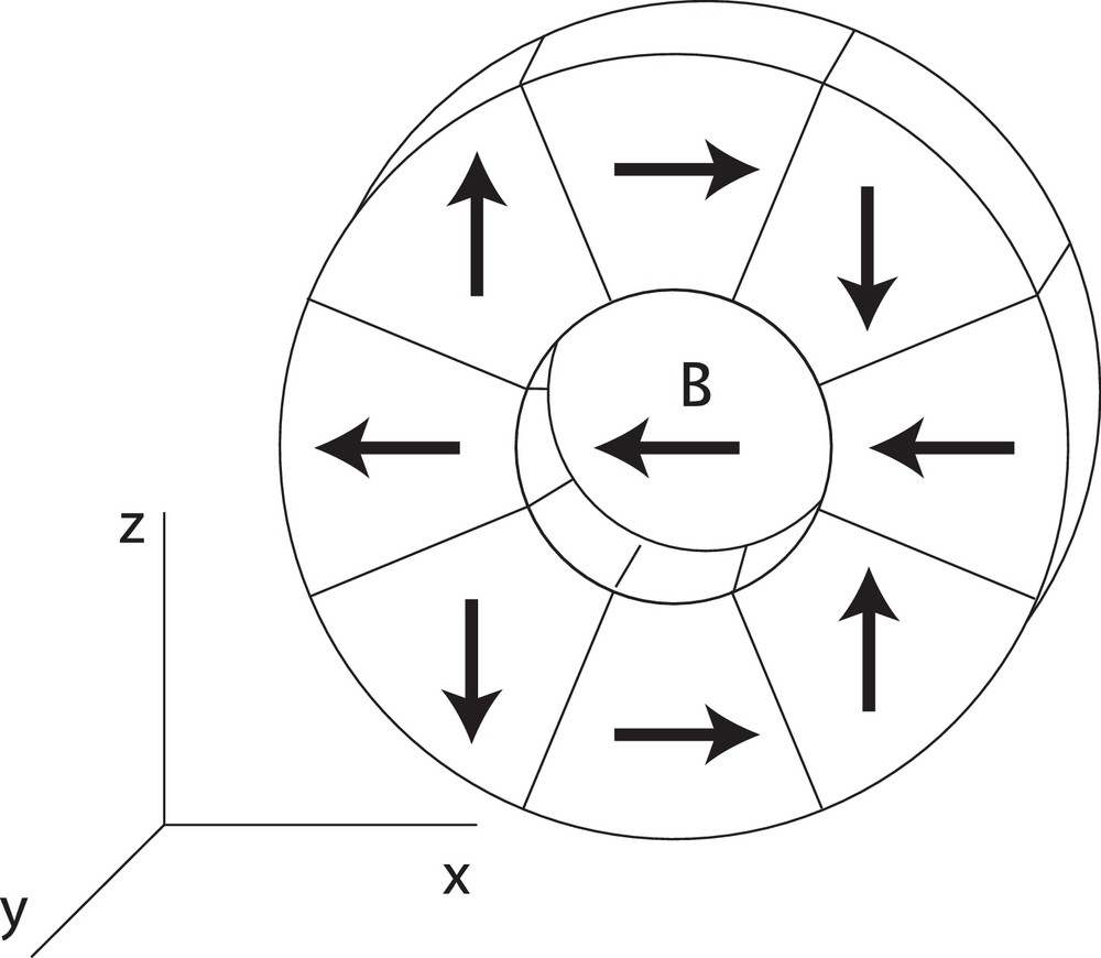
Schematic diagram of a Halbach dipole cylindrical magnet made of eight segments having a variable direction of magnetization as shown on the diagram. The produced field in the centre of the cylinder is oriented along the x axis.
2 The photolithography process
The photolithography process presented in this work aims at manufacturing flexible copper circuits featuring high spatial resolution. Laser-lathe lithography has been used to micro-fabricate coils for portable NMR [14,15], but here the dimensions of our circuits are much larger than a few millimetres. Compared to direct coil winding by hand or by a machine, it is compatible for batch production with the benefit of error reduction. The copper-clad used features copper – kapton – copper layers of respectively 35 μm – 50 μm – 35 μm of thickness (purchased from Farnell CIF AN210). Such a double-layer substrate presents two advantages. One is to double the efficiency of the coil by printing the pattern twice, while connecting the two layers in series. The second is that it allows the compensation of the necessary connections between the coil turns. The copper clad is flexible enough to wind onto a mandrel of at least 1 cm of radius by hand. This makes it ideal for making shim coils for miniature portable MR magnets. The process can be divided into eight main steps as shown in Fig. 2, where the design of negative patterns of the three shim coils is shown.
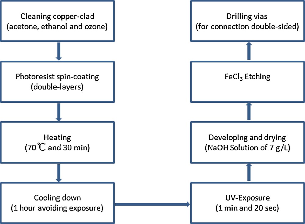
Process chart of the Shim coil fabrication by photolithography on a flexible substrate.
Each coil relates to two aligned mask patterns, one of each as shown in the Fig. 3 for upper layers. Both faces were treated at the same time during the process shown in Fig. 2. The design of the coils was performed using an analytical stream function approach [16], which will be described elsewhere [17]. This approach produces curves that define isolated tracks. In order to be able to supply current to each of the tracks, one has to design connections from one track to the next. These connections are made in a symmetric way between the upper and the lower layers of the circuit so their effects on the field homogeneity are cancelled to first order. The design of the coils produced coils that generate first order gradients for the transverse magnetic field B0 configuration, which are optimized for minimum power dissipation.
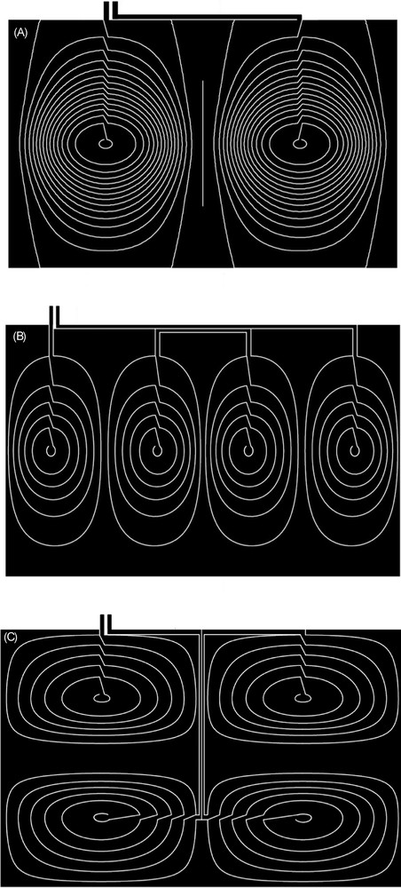
The negative mask patterns for the three first-order shimming coils of Gx (A), Gy (B) and Gz (C) for the Halbach configuration.
For the first step of the coil fabrication, the copper-clad is shaped (cut) to a proper size, leaving a 2-cm margin for easy handling and manipulation. Before processing, it is carefully cleaned by acetone, ethanol, nitrogen and UV ozone cleaning (UVO Cleaner 42 Jelight) for 20 min. The mandrel onto which we wanted to fit them has an outer diameter of 34 mm. In our case, the practical dimensions for dBx/dx, dBx/dy and dBx/dz are respectively 106.5 mm × 67.8 mm, 108 mm × 68.8 mm and 111 mm × 70 mm. The reason for the increasing surface values is the thickness of the etched clad pieces, which is 0.17 mm roughly. Then the cleaned clad is spin-coated with the photoresist (Positiv20 from KONTAKT CHEMIE) with a spinning rotation speed of 60 tr/min during 3 min to obtain a uniform coating between 6 to 8 μm of thickness. The homogeneity of the resist layer of the photoresist coating is crucial to obtain sharp edges on the final coil tracks, particularly in the case of the negative type. The sample is then ready to be heated to remove the solvents of the photoresist and to improve film quality before UV exposing. The sample, fixed onto a steel net support with 8 magnets 10 mm in diameter, should be covered by an aluminium-foil cap during and after resist coating to avoid uncontrolled exposure from the ambient light of the lab, and then immediately placed into an oven. Hence, the sample is heated at 70 °C for 30 min. Next, it is necessary to cool the substrate down to room temperature, for about 1 h.
In the meantime, one can prepare the lithography mask for the upcoming UV exposure, with a transparent foil onto which the coil patterns described in Figs. 2–4 were printed with a laser printer (HP LaserJet 5000 Series). The only requirement for the inking is that the black shading of the laser printing is as dark as possible to define opaque areas stopping UV-A light. The transparent foil used is PRCKIMOLEC of A4 standard, purchased from Bernier Electronik. To obtain a very fine coil pattern, we used a 100%-dark stripes designed on Adobe Illustrator and printed it with a high-DPI printer (1200 dpi is preferred). In these conditions of printing, minimum feature size of 40 μm are achievable. The two identical-area parts of the mask, cut on two transparent foil pieces, are then aligned precisely above a light table, ready for insertion of the sample in between. Then, this arrangement is exposed to eight UV-A light tubes (365 nm, 15 Watts) in a double-sided exposure box (DP134 from CIF during 80 s ± 10 s). It's meaningful to do some trials on small pieces of sample to find out the exposure time for best contrast. After exposure of the sample, a solution of NaOH:H2O at 7 g/l is used for developing the exposed photoresist layer onto the clad for the patterning of the final coil. The developed sample is further copper-etched using a ferric chloride solution (AR414 CIF, purchased from Farnell) at 35 °C in a etching machine (METEOR 220 from CIF) with a conveyor speed of 0.8 mm/s, for a total etching time of 12 min. After drilling and soldering centre holes, the individual layer of the coil fits with the original theoretical design. The resulting fabricated Gx, Gy and Gz coils are shown in Fig. 4. For each type of the shim coils, of Gx, Gy and Gz, at the stage of preliminary fabrication, averaging four times trials of half-finished products were performed to obtain one final one.
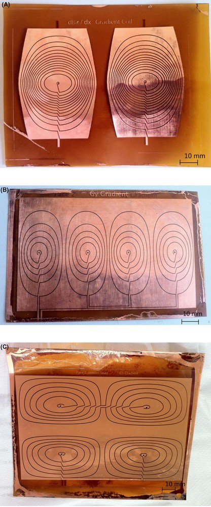
Photos of the processed shimming coils for (A) gradient X, (B) gradient Y and (C) gradient Z. A. Photograph of the planar Gx coil. B. Photograph of the planar Gy coil. C. Photograph of the planar Gz coil.
3 The coil stack and the bench platform for measurement
A test bench was built for the validation of the fabricated first-order shims. As mentioned before, their design is optimized to produce linear-gradients of a magnetic field transverse to the mandrel, along the three perpendicular directions in space. Such magnetic field orientation is present inside a Halbach dipole permanent magnet system. A digital Gaussmeter (LakeShore 460), a motion controller (Newport SMC100) and a DC suppler (TTi EX354RT) were used to build the bench. The home-made motion control software was realized by using Labview 8. The measured resistances were 0.57, 1.17 and 1.13 Ω, respectively for Gx, Gy and Gz. Under 1 A of d.c. current in all three coils, the measured gradients were 0.078, 0.032 and 0.019 mT/mm, respectively for Gx, Gy and Gz. Fig. 5 shows the measured values for the field profiling obtained, as well as the best linear fits.
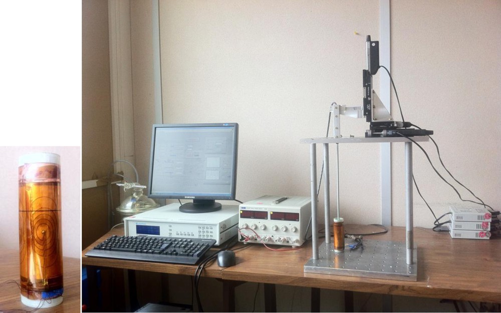
On the left is shown the coil stack of Gx, Gy and Gz shims fitted onto the mandrel, on the right, setup used for the measurement of the shim coils’ magnetic fields.
It is clear from the field profiles shown in Fig. 6 that the linearity is well achieved. The diameter and the height of the coils are 34 mm and 68 mm, respectively. The ratio should be satisfied to 1:2 to keep the linear property of the field. Cross-talking of the coils was not tested, but in stationary operation should be minimal by design and could be corrected using a gradient shimming procedure. Finally, the low resistances of the coils are beneficial to the power dissipation of the coils, which is the parameter used in their optimization.
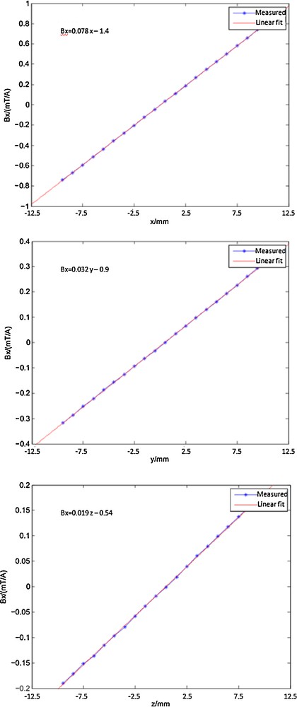
Field profiles for the three shim coils.
4 Conclusion
We have described a simple lithographic procedure for the fabrication of flexible NMR shim coils and demonstrated first experimental results of first-order shims for a transverse field orientation (“Halbach” permanent magnet cylinder). Higher-order coils can also be fabricated using the same approach. Notice however that imaging gradients of similar size would require much more current power and thus it is not recommended to use this approach for their fabrication. Producing truly homogeneous permanent magnets is very important; otherwise the corrections that the electro-shims can provide are not sufficient. In our laboratory, we build permanent magnets having a residual inhomogeneity of ∼10 ppm after passive shimming (i.e. 0.01 mT at B0 = 1 T). In this case, the shims designed here are more than enough for correcting the inhomogeneity. On the other hand, miniaturized versions of gradient sets could be manufactured [18]. This procedure can also be used for making small flexible surface coils and micro-coils for magnetic resonance. Such a production method offers many advantages such as being simple, and cost effective, offering tens of micrometers of minimal resolution, and very fast prototyping in the laboratory, without any need of clean room facilities.
Acknowledgements
The authors would like to thank Mr. Angelo Guiga for helping with machining. The research leading to these results has received funding from the European Research Council under the European Community's Seventh Framework Programme (FP7/2007-2013), ERC Grant agreement 205119.