

1 Introduction
Organoboron compounds have received significant attention in recent years as (fluoride) sensor materials [1–3], for opto-electronic applications [4–6], and for fundamental studies of charge transfer phenomena [7–9]. In the vast majority of these charge transfer studies, the boron center acted as a terminal electron acceptor, but the efficiency of organoboron compounds as molecular bridges (or “wires”) between a donor and a more potent acceptor has not been investigated until very recently. In a study published in 2015, we demonstrated that intramolecular electron transfer between the triarylamine unit and photoexcited Ru(bpy)32+ (bpy = 2,2′-bipyridine) across the organoboron bridge of the dyad in Scheme 1a can be controlled by fluoride anions [10]. Specifically, in the absence of F− intramolecular electron transfer occurred with a rate constant (kET) ≥ 108 s−1, but when two fluoride anions were bound to the organoboron bridge, kET decreased to ≤ 106 s−1. Here, we present results that we obtained on the structurally similar TAA-B-Ru2+ dyad shown in Scheme 1b. We were curious to explore whether the meta-linkage in the new dyad permits an equally efficient switching of long-range electron transfer as in our previously studied dyad.
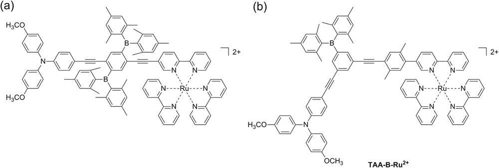
Chemical structures of two triarylamine-organoboron- compounds: (a) Previously studied system [10]; (b) new system presented herein.
The possibility to control the rates of long-range electron transfer is of interest in the greater contexts of a future molecular electronics technology and artificial photosynthesis.
2 Results and discussion
2.1 Synthesis
The synthesis of the key ligand of the TAA-B-Ru2+ compound is illustrated in Scheme 2. The triarylamine donor moiety was introduced into the TAA-B-Ru2+ dyad using the iodo-substituted triarylamine compound 4 which was prepared following previously published protocols [14,15]. The dimesitylboron-substituted bridging unit was prepared starting from 1,3,5-tribromobenzene (5) which was reacted with 2 equivalents of 2-methyl-3-butyn-2-ol (6) to afford compound 7 [16]. The latter was reacted with dimesitylfluoroborane in order to obtain compound 8. Subsequent deprotection with NaH gave the dialkynyl compound 9. The iodo-xylene substituted bpy ligand unit 14 was prepared following our own published protocols [11,15]. Ligand 15 was obtained by reacting triarylamine compound 4, dimesitylboron-substituted bridging unit 9, and bpy ligand unit 14 in 1:1:1 molar ratio using standard Sonogashira coupling conditions. Subsequent reaction with Ru(bpy)2Cl2 afforded the TAA-B-Ru2+ dyad.
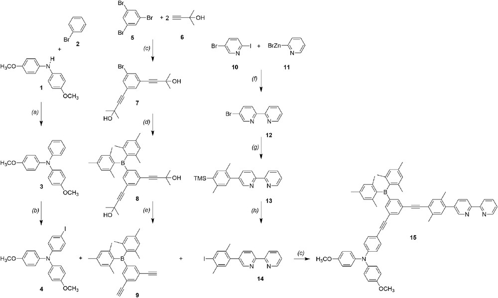
Synthesis of the key ligand for the TAA-B-Ru2+ dyad from Scheme 1b: (a) P(tBu)3H+BF4−, Pd(dba)2, tBuOK, toluene; (b) C6H5I(CF3COO)2, I2, CH2Cl2; (c) Et3N , CuI, PdCl2(PPh3)2; (d) n-BuLi, Bmes2F, Et2O; (e) NaH, toluene; (f) Pd(PPh3)4, THF [11]; (g) 2,5-dimethyl-4-trimethylsilyl-1-phenylboronic acid [12,13], Pd(PPh3)4, Na2CO3, THF/H2O; (h) ICl, CH3CN/CH2Cl2.
2.2 Electrochemistry
Cyclic voltammetry of the TAA-B-Ru2+ dyad was performed in CH3CN containing 0.1 M TBAPF6 as a supporting electrolyte. Oxidative and reductive potential sweeps with rates of 0.1 V/s were conducted separately because this gave higher quality results. Typical scans are shown in Fig. 1. Oxidation of the triarylamine unit is detected at 0.20 V vs. Fc+/0 and oxidation of Ru(II) occurs at 0.77 V vs. Fc+/0, both in line with expectations [10,17,18]. Based on previous studies, [18] we expect that the Ru(II/III) wave overlaps with the wave associated with the oxidation of the triarylamine monocation to its dicationic form. The latter is unstable and can undergo carbazole formation. This explains both the poor reversibility of the wave at 0.20 V vs. Fc+/0 and the significantly stronger current associated with the wave at 0.77 V vs. Fc+/0.
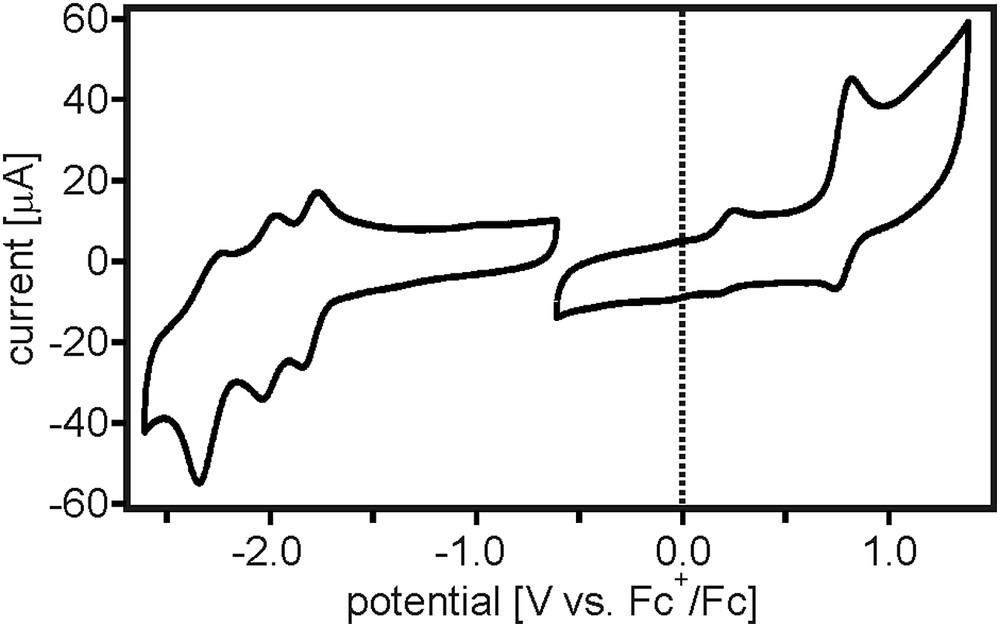
Cyclic voltammograms of the TAA-B-Ru2+ dyad in CH3CN measured in the presence of 0.1 M TBAPF6. Oxidative and reductive potential sweeps with rates of 0.1 V/s were performed separately because this gave higher quality results.
Compared to the previously investigated compound from Scheme 1a, oxidation of the ruthenium center in TAA-B-Ru2+ is approximately 0.33 V easier to perform. Presumably this is due to the fact that in the new system the Ru(bpy)32+ unit is electronically more decoupled from the electron-deficient organoboron unit by the additional p-xylene spacer.
In the reductive sweep, one recognizes three quasi-reversible reduction waves which are attributed to consecutive one-electron reduction of each of the three bpy ligands. Reduction of the boryl bridging unit would be expected to occur at ca. −2.2 V vs. Fc+/0 based previously reported values for comparable compounds [7,10,19–23], but in Fig. 1 the respective reduction cannot be observed unambiguously; we suspect that it is overlapped by one of the bpy-related reduction waves.
Given an energy (E00) of 2.1 eV for the emissive 3MLCT excited state of the Ru(bpy)32+ unit and a distance (RDA) of ∼22 Å between the triarylamine N atom and the Ru(II) center in the TAA-B-Ru2+ dyad [24], the redox potentials (E0) from Table 1 can be used to estimate the reaction free energy (ΔGET0) for intramolecular electron transfer from TAA to the photoexcited ruthenium complex [25].
| (1) |
Reduction potentials (in volts vs. Fc+/Fc) of the individual sub-components of the TAA-B-Ru2+ dyad in CH3CN.a
| E0 [V] | |
| TAA+/0 | 0.20 |
| RuIII/II | 0.77 |
| bpy0/− | −1.82 |
| bpy0/− | −2.00 |
| bpy0/− | −2.29 |
| boryl0/− | −2.20b |
Photoinduced electron transfer leads to oxidation of the triarylamine unit, hence the use of its oxidation potential in Eq. (1). The reduction product is , with the additional electron hosted by a bpy-localized orbital hence the use of the first bpy reduction potential in Eq. (1). Photoexcitation is taken into account by the E00 term which represents the 3MLCT energy of the Ru(bpy)32+ sensitizer. Eq. (1) yields ΔGET0 = −0.2 eV which leads to the expectation of photoinduced electron transfer upon excitation of the Ru(bpy)32+ unit of TAA-B-Ru2+. This driving-force is similar to that previously determined for the dyad from Scheme 1a (ΔGET0 = −0.3 eV).
Attempts to perform cyclic voltammetry in CH2Cl2 were unsuccessful, the resulting data quality was very poor.
2.3 UV–Vis absorption and F− binding
The optical absorption spectrum of a 10−5 M solution of TAA-B-Ru2+ in CH2Cl2 is shown in Fig. 2 (solid line). The 1MLCT absorption band of the Ru(bpy)32+ unit is the lowest-energy absorption feature with a maximum at 460 nm. At 350 nm there is an absorption feature that can be attributed to a N → B charge transfer band, as commonly observed in triarylamine-triarylboron compounds [4,6–8,26–30]. At 290 nm, one detects bpy-localized π-π* absorptions.
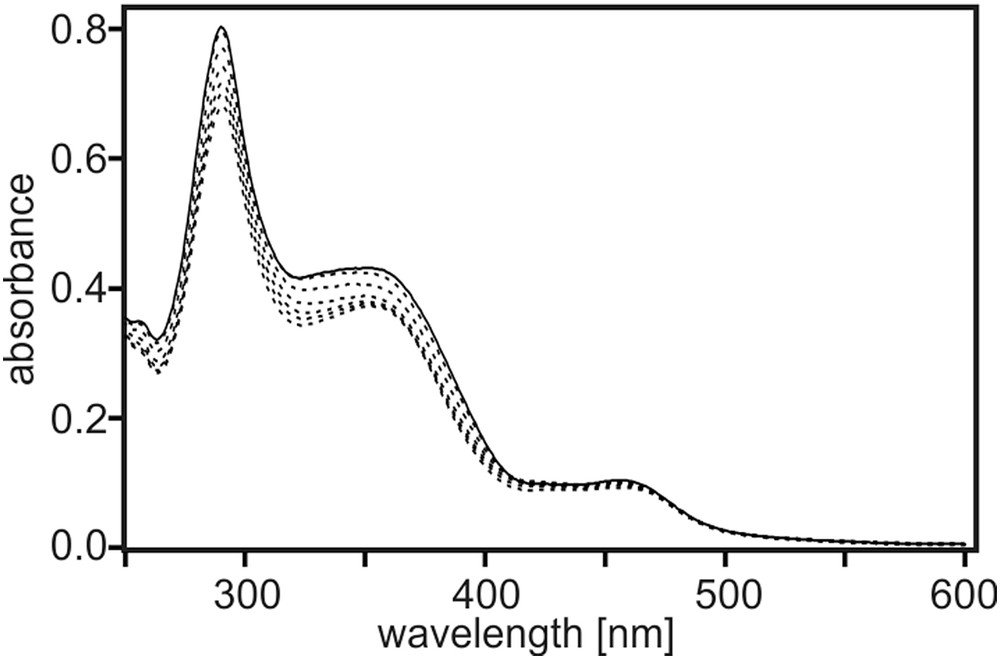
Solid trace: UV–Vis spectrum of 10−5 M TAA-B-Ru2+ in CH2Cl2 at 22 °C. Dashed traces: Spectra measured from the same solution upon addition of increasing amounts of TBAF.
Upon addition of TBAF, the N → B charge transfer absorption decreases (dotted lines), as expected when F− binding suppresses optical charge transfer [7,26]. This kind of observation forms the basis for many fluoride detectors [1,26,31]. In Fig. 3 the absorbance at 370 nm is plotted as a function of F− concentration. This titration curve is based on the solution from Fig. 2 which has a nominal TAA-B-Ru2+ concentration of 10−5 M. Given the presence of one boron atom on the bridging unit of TAA-B-Ru2+, one expects 1:1 association between F− and TAA-B-Ru2+ [1,2]. Consequently, the data in Fig. 3 was analyzed within the framework of a 1:1 binding model to extract an association constant (KA) between F− and the boron center (Eq. (2)) [32–34].
| (2) |
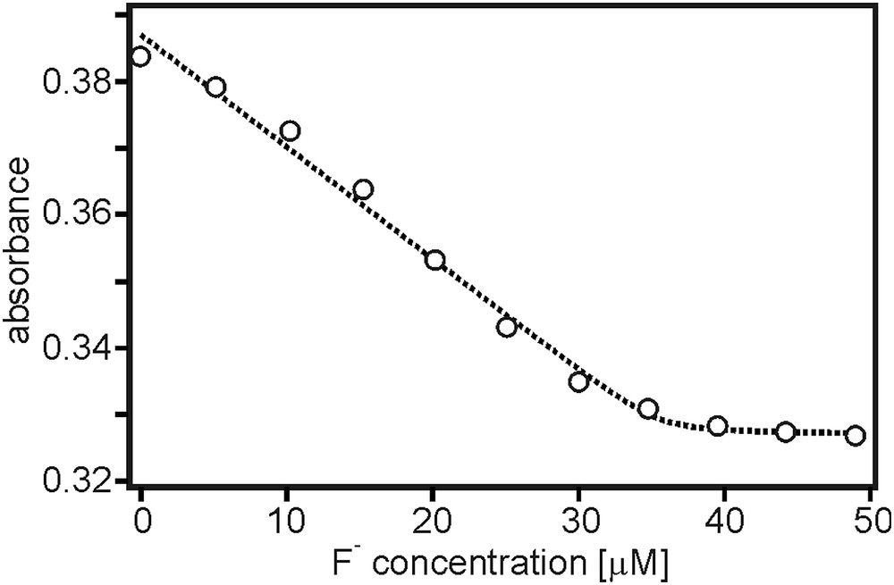
Titration curve based on the data in Fig. 2, displaying the absorbance at 370 nm as a function of fluoride concentration.
In Eq. (2), A(cF) is the absorbance of the sample as a function of F− concentration, and A0 is the absorbance of the initial analyte solution prior to addition of any titrant. Alim is the limiting absorbance value which is obtained in the presence of a large excess of titrant, c0 is the concentration of the analyte (TAA-B-Ru2+). The dotted line in Fig. 3 is the result of a fit with Eq (2) to the experimental data, yielding KA = (1.7 ± 0.5)⋅107 M−1, A0 = 0.387, Alim = 0.327, c0 = (3.5 ± 1.4)⋅10−5 M. The latter had to be a freely adjustable parameter for successful fitting with this binding model. Of key interest here is the apparent association constant, which is in reasonable agreement with fluoride binding studies of chemically related organoboron compounds in similarly apolar solutions [1,2,7,32,35,36]. It should be kept in mind that trace amounts of water can strongly affect fluoride binding due to the high hydration enthalpy of F−.
2.4 Transient absorption spectroscopy and spectro-electrochemistry
Following the excitation of the TAA-B-Ru2+ dyad in CH2Cl2 (10−4 M) with laser pulses of 532 nm wavelength and ∼10 ns duration, the transient absorption spectrum shown in Fig. 4a (black trace) was obtained by time-integrating over a period of 40 ns immediately after the pulses. This spectrum exhibits absorption bands at 420, 540, and 730 nm, in addition to the (weak) bleach at 470 nm. All four of these spectral features can be understood on the basis of the spectro-electrochemical data in Fig. 4b/c.

(a) Transient absorption spectra measured by time-integrating over a period of 40 ns following excitation at 532 nm with laser pulses of ∼10 ns duration. Black trace: 10−4 M TAA-B-Ru2+ in CH2Cl2. Grey trace: 10−4 M TAA-B-Ru2+ in CH2Cl2 containing 2 equivalents of TBAF. (b) Spectro-electrochemistry showing the UV–Vis changes upon oxidation of TAA to TAA+ in the TAA-B-Ru2+ dyad in CH3CN. (c) Spectro-electrochemistry showing the UV–Vis changes upon reduction of to in the TAA-B-Ru2+ dyad in CH3CN.
For the series of UV–Vis difference spectra in Fig. 4b, a potential sufficient for oxidation of the triarylamine unit of TAA-B-Ru2+ was applied to a Pt grid electrode (0.2 V vs. Fc+/Fc). Absorption bands at 420 and 760 nm were detected, as expected [18]. When applying a potential sufficiently negative for bpy reduction (−1.5 V vs. Fc+/Fc), the UV–Vis difference spectra shown in Fig. 4c were measured. In this case, bands at 420 and 490 nm appear along with a bleach at 455 nm, compatible with one-electron reduction of the Ru(bpy)32+ unit [37,38]. In the spectro-electrochemical experiments of Fig. 4b/c the UV–Vis spectrum of the TAA-B-Ru2+ dyad in CH3CN prior to applying any electrochemical potential was used as a baseline, and therefore the resulting difference spectra can be directly compared to the transient absorption spectrum in Fig. 4a (black trace). Based on this comparison we conclude that the photoproduct observed in the transient absorption spectrum contains oxidized triarylamine and reduced Ru(bpy)32+. This is direct evidence for intramolecular photoinduced electron transfer, as expected based on the driving-force estimation made above (ΔGET0 = −0.2 eV). In the following, the resulting photoproduct will be abbreviated as TAA+-B-Ru+.
2.5 Electron transfer kinetics
In Fig. 5 the temporal evolution of the transient absorption signal at 750 nm is shown (black traces). The rise time of the signal is instrumentally limited, indicating that the formation of TAA+-B-Ru+ occurs with a rate constant kET ≥ 108 s−1. The decay is tri-exponential with lifetimes of 20 ns, 135 ns, and >1000 ns. This rather complex decay behavior is most likely owed to the combination of reaction pathways involving intramolecular reverse electron transfer, bimolecular electron transfer, and a degradation process.
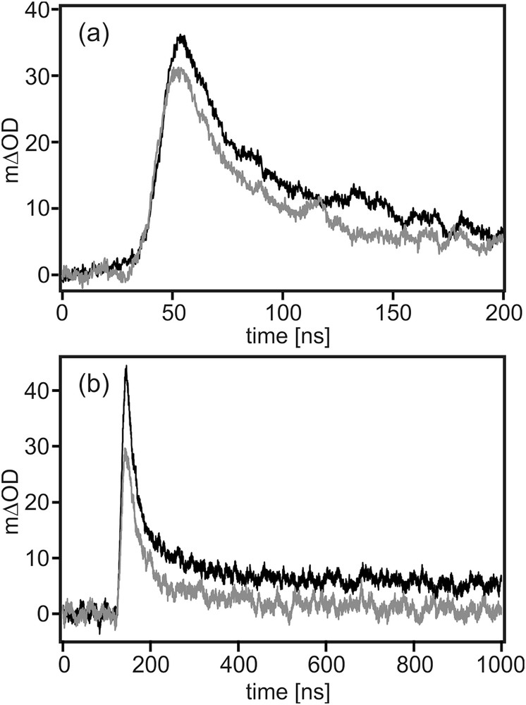
Temporal evolution of the transient absorption signals at 750 nm (from Fig. 4a) on a short (a) and a longer timescale (b). Black trace: 10−4 M TAA-B-Ru2+ in CH2Cl2. Grey trace: 10−4 M TAA-B-Ru2+ in CH2Cl2 containing 2 equivalents of TBAF.
When recording the transient absorption spectra with time delays ≥1000 ns, the typical spectroscopic signatures of TAA+ and cannot be detected any more. Consequently, the slowest time component of the tri-exponential decays is attributed to photo-degradation. The fastest time component (20 ns) is most likely the one associated with intramolecular reverse electron transfer across the covalent backbone of the TAA-B-Ru2+ dyad; for this process one expects comparatively strong electron donor–acceptor coupling, and it seems plausible that this results in rapid electron transfer. The 135 ns time component is attributed to bimolecular processes. Due to the weakness of the transient absorption signals, relatively high sample concentrations (10−4 M) were used, and this increases the probability for intermolecular electron transfer significantly. Concentration dependence studies were not possible because the signals became undetectable upon dilution, and higher concentrations resulted in optical densities which were too elevated.
Thus we find that intramolecular reverse electron transfer occurs with a rate constant of krET = 5⋅107 s−1. Consequently, kET > krET, despite a significantly lower driving-force for photoinduced (forward) electron transfer (ΔGET0 = −0.2 eV) compared to thermal (reverse) electron transfer (ΔGrET0 = −1.9 eV). The inverted driving-force effect is therefore likely at play [39], but there might also be differences in electronic coupling between forward and reverse electron transfer [40,41].
2.6 Effect of F− binding on electron transfer
The grey trace in Fig. 4a is the transient absorption spectrum obtained for 10−4 M TAA-B-Ru2+ in CH2Cl2 in the presence of 2 equivalents of TBAF. The measurement conditions were identical as for the black trace in Fig. 4a. While there are some spectral differences in the range from 400 to 620 nm between the measurements performed in the absence (black) and presence of F− (grey), the overall appearance of the spectra remains rather similar. Most importantly, the triarylamine cation band at 740 nm is clearly observed in both cases, and the spectral feature between 480 and 600 nm (attributed above to the reduced ruthenium complex) can still be detected. Thus one can conclude that photoinduced electron transfer does still occur when F− is bound to the triarylboron bridging unit. The kinetics for TAA+-B-Ru+ photoproduct formation and disappearance are largely unaffected by fluoride binding (grey traces in Fig. 5).
2.7 Comparison to a related organoboron dyad
In a recent study we investigated intramolecular electron transfer from the triarylamine unit to photoexcited Ru(bpy)32+ in the dyad shown in Scheme 1a [10]. The key finding was that F− binding to the organoboron bridging unit decreased kET from ≥108 s−1 in the absence of F− to ≤106 s−1 with two bound fluorides. Here we find that electron transfer across a similar bridge between the same donor and the same acceptor occurs with kET ≥ 108 s−1, regardless of whether F− is bound or not. If any effect of F− on the rate for photoinduced electron transfer is present at all, it has to affect the kinetics on a very rapid (<10 ns) timescale. Evidently, a deceleration of electron transfer to the microsecond time range does not occur. Aside from the presence of an additional p-xylene spacer in the dyad from Scheme 1b, the main differences between the compounds in Scheme 1a and Scheme 1b are the following: The bridging unit in the compound from Scheme 1b contains only one dimesitylboron-substituent which is in the meta-position to the donor and acceptor units, whereas in the compound from Scheme 1a there are two dimesitylboron-groups which are in the ortho- and meta-positions to the donor and acceptor units. Electronic coupling between the ortho- and para-positions of benzene rings is known to be significantly stronger than electronic coupling between meta-positions [42–44]. Consequently, it can be argued that when F− binds to the organoboron unit in the TAA-B-Ru2+ compound from Scheme 1b, this does not affect the electronic coupling pathway between the donor and the acceptor as much as in the case of the previously investigated dyad from Scheme 1a.
3 Summary and conclusions
Photoinduced electron transfer in the TAA-B-Ru2+ dyad from Scheme 1b occurs with a rate constant kET ≥ 108 s−1 regardless of whether F− is bound to the organoboron bridge or not. A deceleration of intramolecular electron transfer to rates on the microsecond timescale in the presence of bound fluoride, such as previously observed for the dyad in Scheme 1a [10], is not detected for the new TAA-B-Ru2+ compound. This contrasting behavior is attributed to the fact that the dimesitylboron unit of the TAA-B-Ru2+ dyad from Scheme 1b is electronically decoupled from the donor–acceptor electron transfer pathway due to its attachment in the meta-position. This strongly suggests that the kET switching observed for the dyad from Scheme 1a is mostly an electronic coupling effect rather than a simple electrostatic effect which arises from the binding of negative charges to the organoboron bridge.
4 Experimental section
4.1 Materials and methods
Compounds 1, 2, 5, 6, 10, and 11 are commercial chemicals which were used as received. Compounds 3, 4, 12, 13, and 14 were synthesized according to our own previously published synthetic protocols [10,15]. All other compounds were synthesized as described below.
Fluoride binding to the TAA-B-Ru2+ compound occurred by the addition of commercial 1.0 M TBAF (tetra-n-butylammonium fluoride) solution in THF. Cyclic voltammetry was performed using a three-electrode setup comprised of a platinum disk working electrode, a silver wire as a counter electrode and a second silver wire as a quasi-reference electrode. A Versastat3-200 potentiostat from Princeton Applied Research was employed. Potential scans were performed with sweep rates of 0.1 V/s, TBAPF6 (tetra-n-butylammonium hexafluorophosphate) was used as a supporting electrolyte in dry, de-aerated CH3CN. A platinum grid working electrode was used for spectro-electrochemistry. NMR spectroscopy was performed using a 400 MHz Bruker Avance III instrument. Mass spectra were recorded on a Bruker Esquire 3000 plus instrument. Elemental analysis was performed by Ms. Sylvie Mittelheisser in the Department of Chemistry at University of Basel using a Vario Micro Cube instrument from Elementar. UV–Vis absorption spectra were measured on a Cary 5000 instrument from Varian. A Fluorolog-322 spectrometer from Horiba Jobin-Yvon was used for steady-state luminescence spectroscopy. Time-resolved luminescence and transient absorption experiments were performed using an LP920-KS spectrometer from Edinburgh Instruments, using the frequency-doubled output of a Quantel Brilliant b laser as an excitation source.
4.2 Syntheses and product characterization data
4.2.1 Compound 7
Following a previously published procedure [16], 1,3,5-tribromobenzene (5.00 g, 15.9 mmol) and 2-methyl-3-butyn-2-ol (3.41 ml, 34.9 mmol) were dissolved in dry triethylamine (85 ml). After de-oxygenating, CuI (4 mol-%) and PdCl2(PPh3)2 (2 mol-%) were added, and the reaction mixture was heated to reflux under N2 for 1 h. Then the solution was cooled to room temperature, and ethyl acetate was added. The mixture was washed with saturated aqueous NH4Cl and with brine. After drying over anhydrous Na2SO4 the solvents were evaporated. Chromatography on a silica gel column occurred first with a 5:1 (v:v) and then with a 3:1 (v:v) mixture of pentane and ethyl acetate as the eluent. This afforded the product as a yellow crystalline solid (3.59 g, 11.2 mmol, 70%). 1H NMR (400 MHz, CDCl3): δ [ppm] = 7.49 (d, J = 1.4 Hz, 2H), 7.40 (t, J = 1.4 Hz, 1H), 1.98 (s, 2H), 1.60 (s, 12H).
4.2.2 Compound 8
Compound 7 (3.38 g, 10.52 mmol) was dissolved in dry diethyl ether (50 ml) and cooled to −78 °C under N2. 2.5 M n-BuLi in hexane (13.9 ml, 34.7 mmol) was added dropwise. Then the cooling bath was removed, and the solution was stirred for 2 h. Prior to adding dimesitylfluoroborane (5.64 g, 21.1 mmol) in dry diethyl ether (50 ml), the reaction mixture was cooled again to −78 °C. After stirring for 10 min at this temperature, the cooling bath was removed, and the mixture was stirred at room temperature under N2 overnight. Then, de-ionized H2O was added and the phases were separated. The organic phase was dried over anhydrous Na2SO4 and then evaporated. The resulting brown oil was purified by chromatography on a silica gel column using first pure pentane and then a 8:1 (v:v) mixture of pentane and ethyl acetate as the eluent. This afforded the product as a yellow crystalline solid (2.99 g, 6.1 mmol, 58%). 1H NMR (400 MHz, CDCl3): δ [ppm] = 7.59 (t, J = 1.7 Hz, 1H), 7.47 (d, J = 1.7H, 2H), 6.82 (s, 4H), 2.31 (s, 6H), 1.96 (s, 12H), 1.58 (s, 12H).
4.2.3 Dialkyne 9
Compound 8 (2.99 g, 6.1 mmol) was dissolved in dry toluene (50 ml), NaH (731 mg, 18.3 mmol) was added, and the mixture was heated to 100 °C under N2 until completion of the reaction (reaction progress was monitored by thin-layer chromatography). After cooling to room temperature, the precipitate was filtered off, and the solvent was evaporated. The solid residue was purified by chromatography on a silica gel column using pentane as the eluent. This afforded the product as a pale yellow crystalline solid (0.72 g, 1.9 mmol, 31%). 1H NMR (400 MHz, acetone-d6): δ [ppm] = 7.70 (t, J = 1.6 Hz, 1H), 7.59 (d, J = 1.6 Hz, 2H), 6.82 (s, 4H), 3.04 (s, 2H), 2.31 (s, 6H), and 1.97 (s, 12H).
4.2.4 Ligand 15
Dialkyne compound 9 (100 mg, 0.267 mmol), iodoxylene-bpy compound 14 (103 mg, 0.267 mmol) [15], and iodo-substituted triarylamine 4 (115 mg, 0.267 mmol) [15] were dissolved in dry triethylamine (20 ml). After de-oxygenating, CuI (4 mol-%) and PdCl2(PPh3)2 (2 mol-%) were added, and the reaction mixture was heated to reflux under N2 for 1 h. Ethyl acetate was added after cooling to room temperature. The mixture was washed with saturated aqueous NH4Cl and with brine. The organic phase was dried over anhydrous Na2SO4 and then evaporated to dryness. Column chromatography on silica gel occurred first with pure CH2Cl2 as the eluent, and then with a 100:10:1 (v:v:v) mixture of pentane, ethyl acetate and triethylamine. This afforded the pure product as a pale yellow solid (23 mg, 0.025 mmol, 9%). 1H NMR (400 MHz, acetone-d6): δ [ppm] = 8.70 (d, J = 4.1 Hz, 1H), 8.67 (d, J = 1.7 Hz, 1H), 8.55 (dd, J = 13.2, 8.1 Hz, 2H), 7.99–7.90 (m, 2H), 7.86 (s, 1H), 7.59 (s, 1H), 7.55 (s, 1H), 7.49 (s, 1H), 7.43 (dd, J = 8.0, 4.2 Hz, 1H), 7.33 (ABq, JAB = 8.9 Hz, 2H), 7.27 (s, 1H), 7.11 (ABq, JAB = 9.0 Hz, 4H), 6.94 (ABq, JAB = 9.0 Hz, 4H), 6.90 (s, 4H), 6.76 (ABq, JAB = 8.9 Hz, 2H), 3.80 (s, 6H), 2.51 (m, 4H), 2.30 (m, 8H), and 1.97 (s, 12H).
4.2.5 TAA-B-Ru2+ dyad
Ligand 15 (155 mg, 0.166 mmol) and Ru(bpy)2Cl2 (80 mg, 0.166 mmol) were heated to reflux in a mixture of CHCl3 (5 ml) and CH3OH (16 mmol) under N2 overnight. Then the solvents were removed on a rotary evaporator, and purification occurred by column chromatography on a silica gel stationary phase. At first pure acetone was used as the eluent, then a 10:1 (v:v) mixture of acetone and de-ionized H2O was employed, and finally a 100:10:1 (v:v:v) mixture of acetone, H2O and saturated aqueous KNO3 solution was used. The solvents were evaporated from the desired chromatography fractions, and the product was re-dissolved in CH3CN. Excess KNO3 was filtered off on a P4 frit. The concentrated CH3CN solution of the product was added dropwise to a saturated aqueous KPF6 solution. The resulting precipitate was washed with de-ionized H2O and with diethyl ether. The pure product was obtained after drying in a vacuum (130 mg, 0.074 mmol, 45%). 1H NMR (400 MHz, acetone-d6): δ [ppm] = 8.90 (dd, J = 12.3, 8.0 Hz, 3H), 8.85 (t, J = 8.8 Hz, 4H), 8.23–8.15 (m, 7H), 8.11–8.07 (m, 5H), 7.92 (d, J = 1.6 Hz, 1H), 7.80 (t, J = 1.6 Hz, 1H), 7.65–7.51 (m, 8H), 7.34 (s, 1H), 7.32 (ABq, JAB = 8.9 Hz, 2H), 7.11 (ABq, JAB = 9.0 Hz, 4H), 6.95 (ABq, JAB = 9.0 Hz, 4H), 6.89 (s, 4H), 6.75 (ABq, JAB = 8.9 Hz, 2H), 3.80 (s, 6H), 2.40 (s, 3H), 2.29 (s, 6H), 2.03 (s, 12H), 1.97 (s, 3H). ESI-MS (m/z): 675.1 (calc. 674.8 for C86H74N7O2BRu2+). Anal. calcd for C86H74N7O2BF12P2⋅4H2O⋅CH3CN: C, 60.31; H, 4.89; N, 6.39. Found: C, 60.56; H, 4.62; N, 6.26.
Acknowledgements
This work was supported by the Deutsche Forschungsgemeinschaft (DFG) through grant number WE4815/3-1.