

1 Introduction
Methane can be decomposed into carbon and hydrogen according to the moderately endothermic reaction:
| CH4→2 H2 + C (s) ΔH = +75.6 kJ/mol | (1) |
Due to the strong C–H bonds, non-catalytic thermal cracking of methane requires temperatures higher than 1200 °C to obtain a reasonable yield. Using a catalyst allows to reduce markedly the temperature. Commonly used catalysts are metal based and carbon based ones [1]. Ni and Fe based catalysts are widely used and exhibit very good activities in methane decomposition. The performance of a catalyst depends on the nature of the support. Common metal supports are alumina, SiO2, metal oxides and zeolites[2].
Carbonaceous catalysts have also been tested in methane decomposition. These materials are less expensive, have a higher temperature resistance and are tolerant to sulfur and other harmful impurities that cause deactivation in metal based catalysts. A wide range of carbonaceous materials for catalytic application in methane decomposition was investigated in the literature [3–5]. The focus is mainly on activated carbons (manufactured from different carbon-based sources) and carbon blacks due to their good activities and stabilities over time.
For instance, Muradov et al. [3] investigated the catalytic activity of various carbon based materials such as activated carbon, carbon black, glassy carbon, acetylene black, graphite, diamond powder, CNT and fullerene. The authors found that there is a linear correlation between the initial methane decomposition rate and the specific surface area of the carbon material. This linear relationship is only valid in the surface area range of 5–1200 m2/g. The authors stated that the catalytic activity of carbon is rather related to its level of structural ordering. The less ordered are the carbons, the most efficient they are for methane decomposition. Thus activated carbons and carbon blacks (amorphous, micro-crystalline) are more efficient for methane catalytic decomposition than graphite, diamond and carbon nanotubes (highly ordered carbons).
Commercial activated carbons (ACs) can also be used as active supports for metal catalysts such as nickel which leads to a net increase in the catalytic activity of the material [6,7]. For instance, Sarada et al. [7] studied the methane decomposition over Ni-loaded coconut shell activated carbon. AC samples were impregnated with an acetone solution containing Ni-nitrate. The authors showed that the performance of the catalyst depends on the loading amount of Ni and its particle size. Decomposition tests were performed for 4 h and showed that the optimal loading of nickel that ensures the best stability and maximum accumulated carbon along cracking (7.92 g C/g Ni) was 23% of Ni in AC.
Biomass chars can also be used as catalysts in methane cracking [8–10]. However, the raw char does not exhibit a sustained activity and is rapidly deactivated by pore blocking due to carbon deposition [11]. Klinghoffer et al. [9] reported maximum deposited carbon amounts of 0.05–0.2 g/g of char, for pine char obtained after gasification with steam and CO2 at different conversion levels, which is a quite low activity.
Biomass chars can be loaded with Nickel for an enhanced catalytic activity in methane cracking. This can be done on the char or before the pyrolysis reaction by impregnating the parent biomass. Nickel wet impregnation on woody materials leads to a very good dispersion of the metal in the wood and in the char after the pyrolysis reaction [12]. Impregnation of the parent biomass has the advantage of providing an intimate contact of the nickel with the biomass during the pyrolysis, which modifies the pyrolysis reaction mechanisms, reducing tars via cracking reactions and enhancing the production of light gases [13,14]. For instance, Blin et al. [14] reported an increase in H2 production of around 260% for a nickel-impregnated wood compared to a pyrolysis test without catalyst. The resulting char containing highly dispersed nickel particles can be used in catalytic cracking of hydrocarbons.
To the best of the knowledge of the authors, nickel-loaded activated carbons or biomass chars used for methane cracking are commonly prepared by a dry mixing or a wet impregnation of the chars. We chose, in the present study, to impregnate the parent material so as to maximize the light gas production during pyrolysis and to obtain a good dispersion of the metal in the final char as proposed by Blin et al. [12,14].
This study focuses on the final Ni-containing chars. Besides the evolution of the catalytic activity in methane cracking, we followed the nickel fate during the three reactions of pyrolysis, methane cracking and combustion. We also looked closely on the deposited carbon structural properties and reactivity.
2 Materials and methods
2.1 Parent wood sample impregnation
Biomass samples are beech wood-chips provided by SPPS Company (France). Raw samples were initially sieved. Biomass particles having sizes in the range of 4–5 mm and thickness of about 1 mm were selected to perform the pyrolysis experiments. Proximate and ultimate analyses of the biomass samples are presented in Table 1. The results are given on a dry basis. The moisture content of the wood-chips was estimated to be 10% ± 1%. Ni-loaded woodchips were prepared following a wet impregnation method [12]. A load of 20 g of wood-chips was impregnated with 200 mL of nickel nitrate aqueous solution (1 mol Ni/l) prepared with Ni (NO3)2 6H2O (Sigma Aldrich, 99% purity). At low pH values, H+ protons compete with Nickel for adsorption on the functional groups. For that reason the pH of the solution was continuously adjusted in the range of 6.5–7 with an ammonia solution (1M). Wood impregnation was carried out for 3 days at room temperature (293 K) and under magnetic stirring. The impregnated wood chips were afterward filtered, washed with 500 mL of deionized water and dried at 323 K for 24 h.
Proximate and ultimate analysis of the beech wood-chips (wt.% on dry basis).
| Proximate analysis | Ultimate analysis | |||||||
| VM | Ash | FC | C | H | O | N | Ni | |
| Raw-wood | 88.1 | 0.4 | 11.5 | 46.1 | 5.5 | 47.9 | 0.1 | 0 |
| Ni-wood | – | 3.0 | – | 42.0 | 5.4 | 51.8 | 0.8 | 2.9 |
2.2 Nickel identification and quantification
The nickel content in the dried impregnated wood sample was determined by optical emission spectrometry inductively coupled plasma (ICP-OES). We developed an analytical procedure involving calcination, mineralization and ICP analysis.
2.3 High-heating rate char preparation
The HHR-chars were prepared in a horizontal tubular reactor facility (HTR) at 850 °C under pure nitrogen. The biomass particles are introduced in the hot zone within 5 s, which allows performing high heating rate pyrolysis. The pyrolysis duration was fixed at 1 min. The char particles are afterward cooled down under nitrogen to room temperature. Details about the experimental apparatus and pyrolysis procedure can be found elsewhere [15].
2.4 Characterisation of the biomass chars
Several techniques were used to characterize the biomass chars before and after the methane cracking reaction.
2.4.1 Chemical composition
The char chemical composition in terms of C, H and N was determined with an elemental analyzer. The nickel content was determined as described above. The oxygen content is determined by difference.
Chemical composition, char reactivities as well as structural properties were investigated using various characterization techniques.
2.4.2 Structural and textural properties
The char was observed via Scanning Electron Microscopy (SEM) performed in a Philips XL30 ESEM apparatus (FEI Company). Char X-ray diffraction data were collected using a Phillips Panalytical X'pert Pro MPD diffractometer with a Cu Kα (1.543 Å) radiation source. The BET surface area of the chars was determined with a MICROMETRICS ASAP 2010 using nitrogen as the gas adsorbate with the data collection in the relative pressure (P/P0) range of 0.03–0.99. Raman spectra of the chars were recorded with a WITec Confocal Raman Microscope (WITec alpha300 R, Ulm, Germany). Raman spectroscopy allows a differentiation of the different carbon allotropes (pyrolytic carbons, graphitic carbons, carbon nanotubes (CNT), diamond etc.,) in the char sample due to their different carbon bond types and orientations.
2.4.3 Char reactivity: temperature programmed oxidation
Temperature Programmed Oxidation (TPO) tests were performed on the initial chars as well as on those containing the deposited carbon after the cracking reaction. Experiments were performed in an STA 409 Netzsch thermogravimetry apparatus. A mass of initial char or char/deposited carbon (DC) composite of about 10 mg is heated to a final temperature of 550 °C (for initial chars) or 750 °C for (for char/DC composite) at 5 °C/min in a 16% O2 containing atmosphere. The final temperature was increased for the combustion of the char/DC sample as it contained a very stable carbon form. The TPO technique allows distinguishing different forms of carbon with respect to their thermal properties and reactivity towards oxygen. These combustion tests were done to check the feasibility of nickel recovery after the cracking reaction as well as to determine the kinetic parameters related to the oxidation reaction of the deposited carbon on the biomass char-Ni support.
2.5 Temperature programmed methane cracking reaction
The catalytic properties of the raw char and Ni-char samples for methane cracking were tested in a TG device. Experiments were done in an STA 409 Netzsch thermogravimetry apparatus. A char sample of about 10 mg is used for the cracking reaction. After a complete reactor purge in a mixture of 5% of CH4 in argon, the char sample is heated – under the same atmosphere – from room temperature up to 900 °C at 10 °C/min and kept at this final temperature for 1 h. The total gas flow was 100 ml/min. The mass evolution of the char sample is recorded throughout the reaction. The methane concentration was fixed at 5% for security reasons. We checked however by a modeling procedure that there are no external mass transfer limitations to the char bed in the most severe conditions of temperature (see annex).
3 Results and discussion
3.1 Nickel impregnation on the wood-chips
Nickel impregnation led to an increase in the O and N contents. This can be explained by the ion exchange mechanism, loss of organic extractible, adsorption of nickel nitrate NiNO3+ and ammonium NH4+ cations which are sources of nitrogen. The alkali content of the impregnated wood was very low (< 0.1%), which can be explained by an exchange mechanism between nickel and alkali and alkaline earth metallic (AAEM) species. Table 1 shows the proximate (volatile matter VM, Ash and fixed carbon FC) and ultimate analysis of the raw and nickel-doped wood.
3.2 Char yields and characteristics
3.2.1 Chemical composition
The char yield, chemical composition and BET surface area of the two chars are given in Table 2. The char yield increased for the Ni-char due to the presence of nickel. The char yields are similar when considering an ash free basis. The carbon content of the Ni char is lower due to a dilution effect. The hydrogen content is also lower than that in the raw char. The nitrogen contents in the two chars are similar while the Ni-char contains more oxygen than the raw one.
Chemical composition, yields and BET surface area of the char samples.
| ychar (%) | C | H | O | N | Ash | SBET (m2/g) | |
| Raw-char | 11.7 | 87.91 | 1.97 | 6.16 | 0.96 | 3 | 69 |
| Ni-char | 15.0 | 74.26 | 0.90 | 10 | 1.06 | 22 | 465 |
The nickel content in the Ni-char was determined by a gravimetric method. The residual mass after combustion tests in the TG device would correspond to the char ash content. Assuming a total recovery of the mineral matter after the pyrolysis step, the ash content (Ni+AAEM) would be 20%. The ash content in the Ni-char was found to be 22% which is slightly higher than the theoretical value. This can be due to the residual carbon remaining in the char or sampling heterogeneity. But, regarding these results, we assume that the initial nickel remains entirely in the char after pyrolysis.
3.2.2 Structural features
SEM observations as well as Energy Dispersion X-ray analysis (EDX analysis) show a good dispersion of the nickel particles throughout the char. Nickel particles appear as bright spots on the SEM image obtained in a backscattered electron mode. An example of the Ni-char surface image is given in Fig. 1.
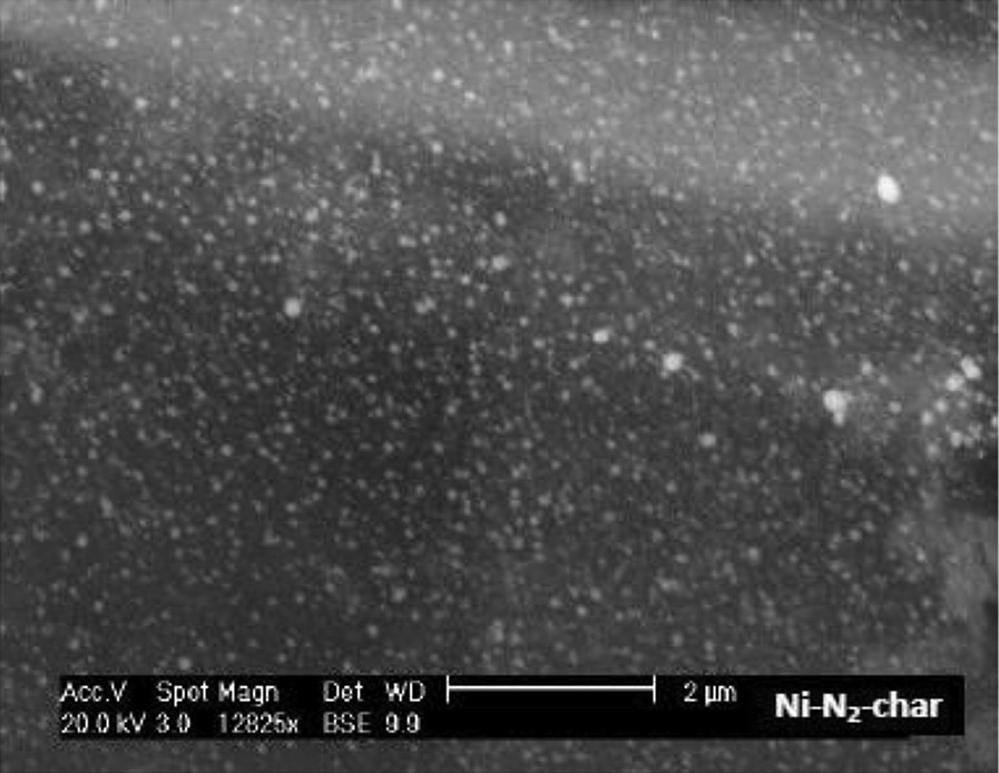
SEM image of the Ni-char.
The size of the nickel particle is quite an important parameter in the methane cracking reaction [16]. The size distribution of the nickel particles shows that 90% of the nickel particles in the Ni-char have average sizes below 100 nm. The nickel particle size is known to be temperature dependent. Kodama et al. [17] impregnated a wood with a nickel solution and heated it to final temperatures of 500 °C and 900 °C. The authors observed that the metallic fcc Ni particle size increased from about 5 nm at 500 °C to 20–200 nm 900 °C. The size distribution found in the present work is similar to that of Kodama et al. at 900 °C.
The BET surface area (Table 2) increased in the presence of nickel, from 69 m2/g in the raw char to 465 m2/g. The nickel is likely to catalyze the in-situ cracking of tars to light gases and hinder tar deposition on the pore mouths, which leads to an enhanced accessible surface area. It was also found in previous studies to catalyze the graphitization of the char at temperatures as low as 500 °C. The inside of the graphitic shells was empty which is a synonym of an ordered structure with an accessible surface [17]. XRD patterns and Raman spectra are discussed in the next sections along with those of the char/DC.
3.2.3 Methane cracking reaction
Fig. 2 shows the mass evolution of the two char samples during thermal decomposition of methane. It can be seen that for the raw char sample the mass initially decreased as a result of further heating and additional cracking. The mass decay was 6%. The nickel-loaded char showed very slight mass decay during heating. The nickel would have catalyzed the tar cracking into light gas during the pyrolysis so that no further release is observed during additional heating.
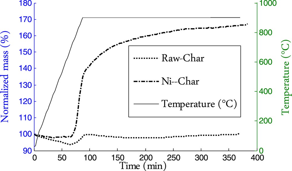
Mass evolution of the char samples during thermal decomposition of methane.
Methane decomposition reaction is assessed through the mass gain of the char sample corresponding to the amount of deposited carbon as a result of the methane decomposition into hydrogen and carbon following reaction (1). Since no other gaseous species except methane and argon are present in the reactor, it is therefore admitted that the mass gain corresponds to carbon deposition. Knowing the mass gain, we can determine the amount of deposited carbon, the amount of hydrogen produced and methane cracked by performing a straightforward mass balance.
Table 3 summarizes the TG results related to the methane cracking reaction as follows:
- • the starting temperature of the reaction: Tstart
- • the maximum reaction rate rmax (%/min)
- • the temperature at the maximum reaction rate
- • the final amount of deposited carbon YDC (g/g of char)
- • the final molar yield of H2 : (mmol/g of char)
Methane-cracking reaction characteristics.
| Char sample | Tstart (°C) | rmax (%/min) | (°C) | YDC (% of char) | (mmol/g of char) |
| Raw-char | 704 | 0.743 | 900 | 6.7 | 11.2 |
| Ni-Char | 704 | 3.0436 | 855 | 69.5 | 115.8 |
We can note that the raw char exhibits a moderate, but non-negligible, catalytic activity for methane decomposition. The amounts of deposited are 6.7 g/100 g of char. Klinghoffer et al. [9] found similar amounts in the range of 5–20 g/100 g of char for chars gasified with CO2 or H2O in a pilot fluidized bed. Diffusion limitation and pore blocking are likely behind the rapid saturation of the char pores as reported by several authors [10,11]. The carbon deposited has also a low catalytic activity for methane cracking, if not, the process would be continuous over time [18,19].
Nickel loading greatly enhances the methane decomposition reaction as shown in the TG curves. The amount of deposited carbon increased by 10 times for the Ni-char compared to the raw one. The amount of deposited carbon was 69.5 g/100 g of char. The starting temperature of the methane decomposition was 704 °C for both chars. The temperature at the maximum reaction rate decreased by near to 50 °C for the Ni-loaded char.
3.2.4 The nature of the deposited carbon
3.2.4.1 SEM observations
SEM images of the char/DC after the cracking reaction are depicted in Fig. 3. It can be seen that the carbon from methane grows on the char surface in the form of “filamentous” carbon and “carbon balls”. Both forms are growing on the nickel particles which are encapsulated inside. The deposited carbon forms a kind of shell around the nickel particles. Nickel particles can be observed either at the tip of the growing filaments or trapped along the hollow core of the nanofibers. These two forms have been reported in the literature [20,21]. Suelves et al. [21] observed the formation of similar carbon fibers on a commercial catalyst containing 65wt% of Ni supported on a mixture of silica and alumina. The amount of deposited carbon was in the range of 0.5–9.3 g of deposited carbon/g of Ni, depending on the experimental conditions. In our case, the carbon yield is around 3 g of DC/g of Ni, nickel being considered as the active phase of the catalyst.
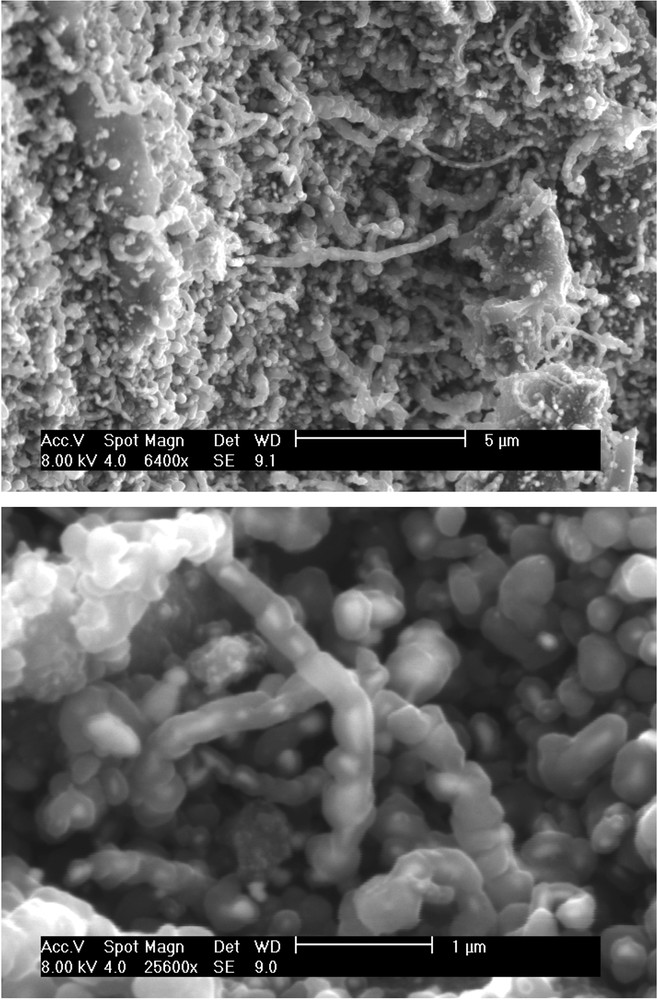
SEM images of the Ni-char surface after the cracking reaction.
The mechanism of the formation of filamentous carbon has been thoroughly investigated from kinetics and thermodynamics considerations [22]. Similar carbon filament formation has been observed over various catalysts such as Ni/activated carbon [6], activated carbons from coal or coconut shell in which the carbon filament formation has been attributed to iron and alkali species [23]. These observations indicate that the mechanisms of formation and growth of filamentous carbon on different supports are quite similar.
3.2.4.2 X-ray diffraction
The XRD pattern of the raw char does not show a crystalline structure. However, crystalline structures have been observed for the Ni-char sample before and after the methane decomposition reaction. The results are shown in Fig. 4. Before the cracking reaction, the Ni-char reveals the presence of crystalline Ni metal nano-phases with a face-centered cubic structure. This was expected regarding the results of Richardson et al. [12]. The XRD patterns of the Ni-loaded chars after the reaction are quite different from those of chars before the cracking reaction. Reflections at 44.5°, 51.7°, 76.3° and 98.4° corresponding to metallic nickel are still present, however other rays appear. We can distinguish a very intense reflection at 2θ = 26.1° corresponding to a basal (0 0 2) inter-layer spacing (d = 0.338 nm) of a graphitic carbon. The rays at 42.53° and 43.23° correspond, respectively, to the graphite (1 0 0) and (1 0 1). Reflection at 53.8° is attributed to graphite (0 0 4) while that at 77.6° is due to graphite (1 1 0). Reflections at 37.3°, 62.8° are quite ambiguous as they do not belong to metallic nickel nor to conventional graphite. Unless they belong to an unknown carbon crystal structure, they would most probably be assigned to planes (1 1 1) and (2 2 0) of NiO, however we do not know by which mechanisms NiO is formed since it was not detected in the Ni-loaded char before the methane decomposition reaction.
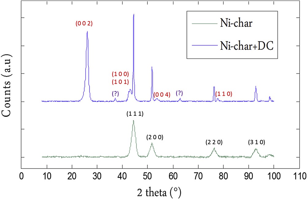
XRD patterns of the Ni-char before and after the methane decomposition reaction (Ni-char+DC). In black and red color respectively, indexes of the rays corresponding to Nickel and Graphitic carbon.
The deposited carbon is likely growing in the form of graphitic layers while the deposited carbon on the free-nickel chars was an amorphous one. No rays related to an ordered structure were observed and the XRD patterns before and after the reaction were quite similar to no crystalline phase.
3.2.4.3 Raman spectroscopy
Fig. 5 shows the Raman spectra of the free and nickel loaded chars before (Raw-char/Ni-char) and after the methane cracking reaction (Raw-char+DC/Ni-char+DC). These spectra show a common feature corresponding to 2 well-known bands related to carbon materials.
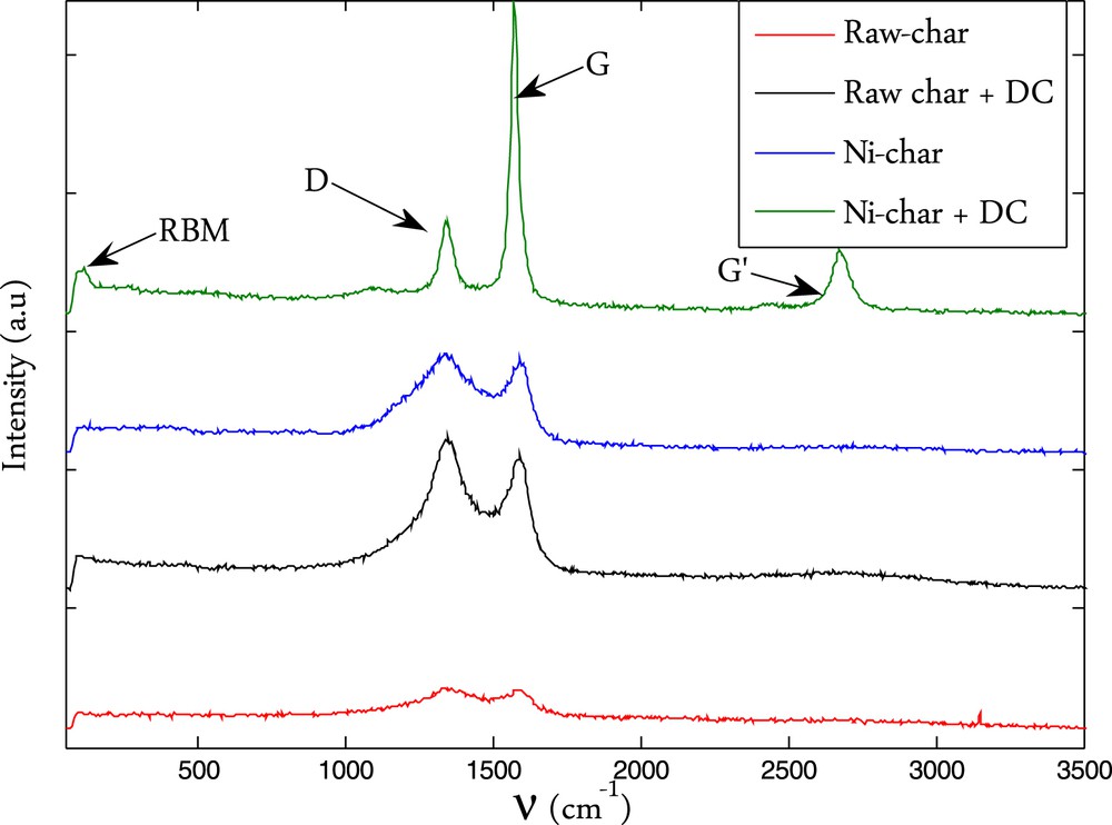
Raman spectra of the different samples.
The first band corresponds to the D-band (defect band) which appears typically in the wavenumber range of 1330–1360 cm−1. This D-peak is related to a breathing mode of A1g symmetry. This mode is forbidden in perfect graphite and only becomes active in the presence of disorder. This mode is also dispersive as it varies with the photon excitation energy. The intensity of the D-peak decreases with the extent of the presence of six fold rings corresponding to a more ordered structure [24]. The second band in the wavenumber range of 1570–1590 cm−1 corresponds to the G-band (graphite band). The vibration G mode of graphite has an E2g symmetry corresponding to an in-plane bond-stretching motion of pairs of C sp2 atoms. The G mode does not require the presence of six fold rings, and therefore takes place at all sp2 sites, including those which do not belong to a multi-ring system. It is found for example in the spectra of aromatic molecules. For disordered carbon such as in biomass char, another signal corresponding to the amorphous carbon known as the A band would appear as a broad peak at 1500 cm−1 [19]. A deconvolution process is therefore necessary to show the hidden peak. The more the char contains amorphous carbon, the more this A-band is intense, and the less the D and G peaks are separated. Moreover, the deconvolution process allows having the accurate integral intensity of the D and G bands, the ratio of which, I(D)/I(G), has been demonstrated to be a good representative of the microstructure of a heterogeneous carbon material [19]. In the deconvolution process, we considered these 3 peaks and a curve fitting method including Lorentzian and Gaussian lines. The deconvoluted signal is presented in Fig. 6.a and b for the raw char and Ni-char and in Fig. 6c and d for raw-char+DC and Ni-char+DC. We can see that the Raman signal is quite well represented by these three main peaks. We can see for the raw char that the signal corresponding to the amorphous carbon (A-band) slightly decreased after the cracking reaction in comparison with the G and D bands which become sharper and more separated. This is due to the ordered carbon deposition and continuous heating of the sample that reduces the amorphicity degree.
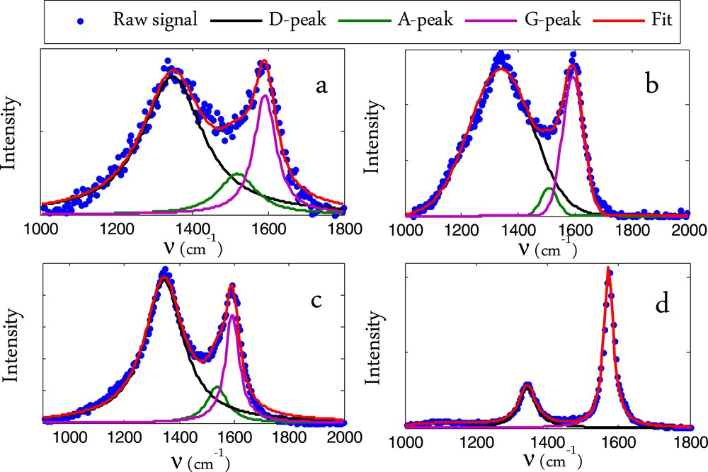
Raman signal deconvolution for the char sample before and after the cracking reaction. a: Raw char, b: Ni-char, c: Raw-char+DC, d: Ni-char+DC.
The A-band signal is relatively much lower than the D and G peaks in the Ni-char. This again confirms the role of the nickel in catalyzing the graphitization of the char. The A-band signal completely disappeared after the methane cracking reaction. Even if an amorphous carbon is still present, its signal would be quite lower than those of the inherent graphitized carbon and the well-ordered deposited one. The different peak positions as well as the ordering index IG/ID are given in Table 4.
Main peak position and IG/ID ratio for the different carbonaceous samples.
| Char | D peak | A peak | G peak | IG/ID |
| R-char | 1349 | 1520 | 1592 | 0.99 |
| Ni-char | 1344 | 1536 | 1590 | 0.97 |
| R-char+DC | 1339 | 1509 | 1592 | 0.99 |
| Ni-char+DC | 1344 | – | 1572 | 1.42 |
For the Ni-char, after the cracking reaction, another peak appears at 2674 cm−1. This one is characteristic of the graphite material which consists of stacks of sp2 bonded planar graphene sheets. Its intensity is less than the intensity of the G-band. The reverse case is observed for single graphene layers. The deposited carbon from methane likely forms a graphitic structure on the nickel loaded char. Another worth-noting fact is that a small peak appears at the very beginning of the spectra at 118 cm−1. This peak is specific to the Radial Breathing Mode or RBM bands. The RBM bands are unique to Single Walled Carbon Nano-Tubes (SWCNTs) and as their name suggests, corresponding to the expansion and contraction of the carbon nanotubes (CNT). Altogether, these data indicate that the deposited carbon is well ordered and it is mainly in the form of graphite. It can also form CNT on the small Ni particles which are scarce in the present case.
3.2.4.4 Reactivity to oxygen: temperature programmed oxidation
The reactivity to oxygen of the Ni-char was investigated before and after the cracking reaction. The TG data are given in Fig. 7. The heterogeneous carbonaceous material (Ni-char+DC) is clearly far less reactive to oxygen than the initial biomass char. The oxidation reaction started at 510 °C for the Ni-char+DC composite while it started at about 320 °C for the Ni-char. The well-ordered deposited carbon is likely behind this thermal stability. The oxidation peak temperatures were, respectively, 400 °C and 630 °C for the initial chars and the Ni-char/DC composite. Similar oxidation parameters were reported by Pham-Huu et al. for the combustion of a Ni-loaded graphite/carbon nanofibers composite [25]. The Ni content of the composite is 11.83%. The theoretical value assuming that the nickel remains in the char during the cracking reaction would be 12.9% which is quite similar. Here again, considering that the sampling before the combustion reaction does not allow to have the exact composition of the composite sample obtained after the methane decomposition, we can attribute this discrepancy to the sampling precision and consider that the nickel is recovered entirely after the combustion reaction.
- • Kinetic parameters of the deposited carbon combustion reaction:
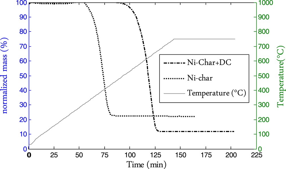
Combustion TG curve of the Ni-char and Ni-char+DC.
The thermal stability of a carbonaceous material can be assessed through evaluating its reactivity to oxygen in a defined range of temperature. The thermal stability is also an index of the carbon ordering. The more the carbon oxidation reaction starting temperature is high, the more the carbon is ordered [25,26]. These results are in accordance with those observed in the Raman analysis. The Raman spectra of the Ni-char sample after the methane cracking reaction showed the presence of a highly ordered carbon as the D and G peaks were well separated. The higher thermal stability and lower reactivity with oxygen of the deposited carbon are related to its ordered form.
Fig. 8.a shows the DTG curve of the initial Ni-char. The DTG curve of the Ni-char oxidation shows one main peak with a small shouldering in the beginning. It has been reported that the presence of nickel catalyzes the hydrocarbon (HC) cracking as well as the carbon graphitization during the pyrolysis step [12]. We assumed that the shouldering corresponds to the oxidation of a carbon (C1) formed on the nickel particle during the pyrolysis as a result of the HC cracking catalyzed by the nickel particles. The main carbon is that relative to the biomass char Cchar. The total carbon mass is given by the following equation:
| (2) |

Ni-char and Ni-char+DC reactivity modeling.
The combustion reactions are considered to be first order reactions with respect to oxygen as well as C1 and Cchar [27], the model then reads:
| (3) |
| (4) |
The best fitting parameters are given in Table 5. It can be seen in Fig. 8 that with these parameters, the model fits well to the experimental results. The Cchar mass is found to be 73 g while the C1 carbon mass is found to be 3 g. The sum is quite close to the theoretical carbon amount of 78 g. The activation energy of Cchar is found to be 139 kJ/mol which is the range of the activation energies given in Di Blasi's review for the combustion of biomass chars [28]. That of the C1 carbon is around 200 kJ/mol corresponding to a more ordered carbon form.
Modeling parameters for the Ni-char combustion reaction.
| (g) | (s−1) | (kJ/mol) | (g) | (s−1) | (kJ/mol) |
| 3 | 3.1012 | 203 | 73 | 95,000 | 139 |
Concerning the Ni-char/DC sample, we assumed that it contains two defined carbon types, namely Cchar for the biomass char and Cdep for the deposited carbon. We neglected C1 because of its low contribution in the mass of the final product Ni-char/DC.
The combustion reaction of the composite sample is considered to be the result of two parallel combustion reactions of Cchar and Cdep. The combustion reactions are considered to be first order reactions with respect to oxygen as well as to Cchar and Cdep.
According to the experimental data, in 100 g of the composite sample there would be mNi = 12 g, = 46 g, = 42 g. Moreover, the activation energy of Cchar is already defined by the first combustion experiment.
The mathematical transcription of these assumptions gives:
| (5) |
One can see in Fig. 8 that the modeling results are quite satisfactory. The kinetic parameters determined for the best fit are given in Table 6. The mass values of the two carbon forms are quite close to those given by the experiment. The activation energy of the DC oxidation is twice as high as that of the Cchar carbon. This quite high activation energy reflects the oxidative stability of the DC. These results are corroborated by the Raman analysis showing that the deposited carbon is highly ordered.
Modeling parameters for the Ni-char/DC combustion reaction.
| (g) | (s−1) | (kJ/mol) | (g) | (s−1) | (kJ/mol) |
| 47 | 120 | 139 | 43 | 35.1010 | 301 |
4 Conclusion
The nickel wood char exhibits a good catalytic activity in methane cracking compared to a free-nickel wood char. Nickel being the active catalyst, the H2 production was estimated to be 527 mmol/g of nickel. The deposited carbon forms a shell around the nickel particles. The whole is in the form of balls or filaments. The deposited carbon is highly graphitized as evidenced by XRD and Raman analysis. The end product is much more stable thermally due to the ordered nature of the deposited carbon. The activation energy in the combustion reaction of this latter was estimated to be around 300 kJ/mol, twice that of the conventional biomass char.
From a process point of view, this application is far from being complete in many aspects: economic, energetic and ecological. This study is an exploratory one aiming at testing the effectiveness of biomass char as a metal support to crack methane and explore some aspects of this reaction. Some plants accumulate metals such as Ni, Pb, Zn and Cd in non-negligible quantities (1–3%) such as A. murale. These plants are commonly used for soil depollution. After harvesting and pyrolysis, the resulting char can be valorized and used as a catalyst for methane cracking or similar reactions.
Acknowledgment
The author would gratefully thank Mr. Bernard Auduc for his technical support as well as Lauraine Haury for her help in the Raman spectroscopy analysis at the GALA platform.
Appendix Mass transfer modeling in the TG device
To check the accuracy of the thermogravimetric data, so that the reaction rate is effectively determined for a CH4 concentration of 5% at the char bed surface, we considered a monodimensional diffusion model involving the diffusion of CH4 from the top of the crucible where the concentration is ∞ = 5% to the char bed where the concentration is bed (zone 1), and a diffusion within the char bed with a volumetric reaction term (source term) corresponding to the methane consumption and hydrogen production (zone 2). Schematic representation of the TGA crucible.
Fick's second law in a steady state regime gives:
| (A1) |
- • Di-Ar is the diffusion coefficient of species i in argon [m2/s]
- • Ri is the source term [kg/m3.s].
We considered in the present case the maximum reaction rate observed = 3%/min at T = 900 °C.
In the char bed (zone 2) an effective diffusion coefficient is calculated using the following relation:
| (A2) |
- • ɛ: porosity ɛ = 0.9
- • τ: tortuosity τ = 3.
The effective diffusion coefficients in the char bed are corrected by the ratio ɛ/τ.
CH4 consumption in the bed was calculated to be 0.134 kg/m3.s for char bed dimensions of l = 5 mm, L = 5 mm and h1 = 1 mm.
The results of the model are shown in the figure below. The methane concentration at the bed surface is 4.5%. The thermogravimetric data are hence valid for our operating conditions. Methane concentration profile for the maximum reaction rate at 900 °C.