

1 Introduction
Olefin metathesis reactions represent a powerful catalytic tool for the formation of carbon–carbon double bonds allowing the preparation of various chemical intermediates useful for the synthesis of fine chemicals, pharmaceuticals, and polymers [1,2]. The three major contributors to olefin metathesis development and achievements shared the Nobel Prize in Chemistry in 2005 [3–5]. For examples of industrial applications of olefin metathesis technology, the reader is directed to a review by Fogg et al. [6]. The successful progress in olefin metathesis stems from the transformation of unsaturated renewable resources such as fat and oils [7], terpenes [8], and Z-selective transformations [9]. Such reactions are catalyzed by organometallic soluble catalysts of ruthenium, tungsten or molybdenum, which are all quite expensive compounds [10,11]. Among olefin metathesis catalysts, commercially available ruthenium-based Grubbs and Hoveyda–Grubbs precatalysts (Fig. 1) have received a lot of attention at a laboratory scale as they combine high stability and activity with an excellent tolerance toward polar functional groups, hence allowing reactions with various substrates/reactants. It is important to note that the actual catalytic species is generated from precursors such as Grubbs and Hoveyda–Grubbs complexes (herein called precatalysts) by in situ activation in the presence of the substrate. Despite the broad range of applications accessible by olefin metathesis, only few industrial processes use metathesis reactions because of the cost of homogeneous catalysts together with difficulties for the final separation of the reaction products from the various metal-containing species at the end of the reaction. Depending on the target application the residual amount of metal must be very low in the final product. Therefore, several procedures have been developed to reduce this metal content of which precatalyst immobilization has to be considered as a preferred strategy if the productivity of the reaction can be ensured [12–14]. Furthermore, precatalyst immobilization is also a very valuable strategy to increase the catalyst productivity quantified through its turnover number (TON=moles of reactant converted per mole of catalyst) obtained for a single load of the precatalyst and a sufficient load (continuous or discontinuous) of the substrate. Precatalyst recovery and subsequent reuse, a process quoted as “catalyst recycling” has been addressed via heterogenization of the Hoveyda–Grubbs precatalysts by immobilization in nonconventional solvents [15–18] or on an insoluble porous solid material, generally silica, the particles of which are being easily separated by classical filtration of the reaction medium. This immobilization can be achieved either by a covalent grafting [19–23], by adsorption owing to electrostatic attractive interactions leading to an ionic bond [24,25] or by simple adsorption [26,27].
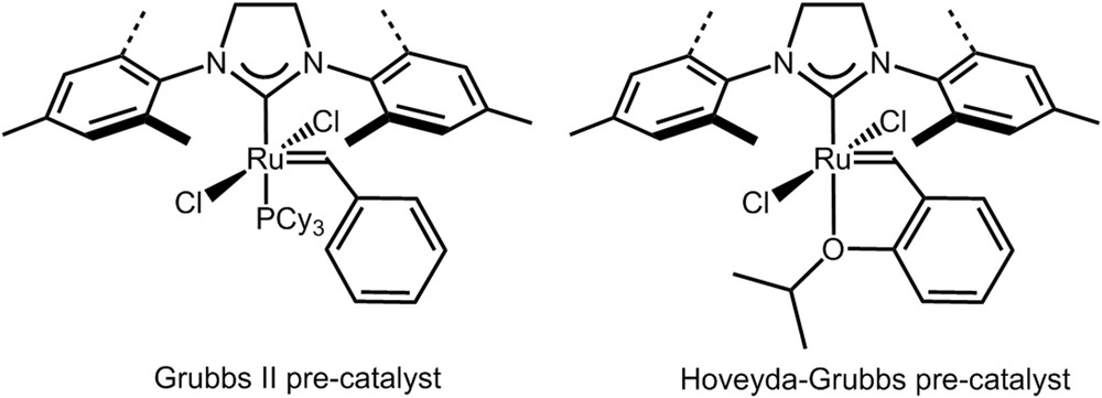
Example of Grubbs II and Hoveyda–Grubbs precatalysts (Cy = cyclohexyl).
Among these different immobilization routes, grafting through covalent bonding seems advantageous for the design of stable and recoverable immobilized Hoveyda–Grubbs precatalysts. This route should prevent leaching problems allowing for the possible adaptation to scalable industrial processes. Grafting through covalent bonding is generally carried out by a reaction of hydroxyl groups (−OH) of porous oxide particles with an organosilane linker of the general formula (R′O)3SiR.
Using such approach, the global catalytic process can be run in a semicontinuous mode with oxide particles in suspension in a batch reactor and sequential filtration to separate beads from the solution. It can also be achieved in a continuous mode by packing the particles in a more or less fluidized bed, avoiding the subsequent separation step by filtration. However, such process suffers from pressure drop, which must be carefully controlled and managed.
Another possible strategy is based on the mastering of the separation itself without any modification of the precatalyst. Following this idea, in the recent years, membrane technology has appeared as a promising and environmentally friendly alternative approach for process intensification in organic (fine) chemistry as it allows, in principle, the separation and reuse of homogeneous catalysts [28,29]. This idea has been developed especially with organic solvent nanofiltration (OSN) after the development of suitable polymeric membranes such as Koch (PDMS), Starmem (PI), and DuraMem [30]. Many research groups have investigated OSN for separation and reuse of homogeneous catalysts using such “inert” membranes [31–33]. In the case of olefin metathesis reactions, previous works from our group [34–36] and others [37–41] implemented OSN for the recovery of Hoveyda–Grubbs precatalysts as the starting point to increase the apparent turnover number in selected model reactions. Nevertheless, to the best of our knowledge the transfer from laboratory to industrial scale has not been achieved as technical improvements are still required. We previously proposed a comparison of several systems applied to olefin metathesis based either on simple separations by OSN or on the use of a synthesis membrane reactor running in continuous or discontinuous mode [35].
What about the coupling of the two strategies described just above? In others words, what about the immobilization of the catalyst on a porous membrane support, integrating synthesis, and separation in a single operation? Such a strategy would increase the process intensification by proposing a real continuous process in a catalytic membrane reactor reducing problems related to pressure drop management encountered with more or less packed bed.
In this respect, modified polymeric membranes have been used as catalytic membranes [28,42]. The heterogenization of a homogeneous catalyst in polymeric membranes can be achieved by occlusion, entrapment or encapsulation of the homogeneous catalyst inside or on the membrane surface [28,43].
For instance, Vankelecom et al. [44] studied the encapsulation of the Ru-MeDuPhos (MeDuPhos = (−)-1,2-Bis[(2R,5R)-2,5-dimethylphospholano]benzene) catalyst on a PDMS-based membrane (PDMS = PolyDiMethylSiloxane) for the hydrogenation of methyl acetamidoacrylate. Mac Leod et al. [45] studied the encapsulation of the Jacobsen catalyst in a PDMS-based membrane and used it for oxidation of alkanes and alkenes. Our group studied the elaboration of a metathesis catalytic membrane by immobilization of an ionically tagged Hoveyda–Grubbs precatalyst on a polyimide membrane previously modified by adsorption of an ionic liquid [46]. Drioli et al. [47] embedded Salen-Co(II) complexes into polymeric membranes and used them for the cyclopropanation reaction in a catalytic reactor.
However, such catalytic membranes suffer from catalyst leaching issues resulting from the noncovalent linkage between the organometallic catalyst and the polymer membrane. To overcome the leaching problem and design a stable catalytic membrane, a similar approach as the grafting on silica particles [48], that is, by a covalent link between an organometallic catalyst and a ceramic membrane, seems advantageous. Furthermore, higher chemical and mechanical stabilities will be brought by these inorganic membranes as compared to organic ones.
In the literature, heterogeneous catalysts (metal, catalyst particles) have been widely used to elaborate catalytic membranes [49,50]. Generally, immobilization of heterogeneous catalysts in the active layer of a ceramic membrane was realized by an impregnation process or by incorporation of catalyst particles during the preparation of the active layer. The presence of hydroxyl groups on the surface of inorganic membranes allows modification and compatibilization of the membrane for a wide variety of applications in diverse fields such as OSN [51,52], separation of gas [53], and membrane distillation [54].
Among the different techniques for the modification of inorganic membrane surfaces, chemical grafting with organosilanes is the most frequently used method [52]. The chemical grafting of zirconia membranes has been reported by many researchers for different applications [55]. For instance, in 2004 Picard et al. [56,57] reduced the hydrophilicity of the surface of zirconia ultrafiltration (UF) membranes by grafting of perfluoroalkylsilanes.
In 1999, our group [58] patented the modification of a zirconia membrane by grafting of organotitanate-bearing pyrophosphate, alkyl-substituted pyrophosphate, or amine groups to improve protein rejection and prevent fouling in UF and also to prepare membranes for the chelation of metal cations. Using the same modification methodology, our group studied the modification of a zirconia membrane aiming at recovering the commercial Hoveyda–Grubbs precatalyst by nanofiltration [59].
To the best of our knowledge only one study has reported the elaboration of a catalytic membrane by grafting a homogeneous catalyst on the surface of a ceramic membrane [60]. In this article, Liu et al. reported the grafting of Salen-Mn(III) onto an APTES-modified ceramic membrane (APTES = aminopropyltriethoxysilane) and its performances in epoxidation of styrene.
The main objective of the present study was to develop an innovative strategy bridging the concepts of (1) heterogenization of homogeneous catalysts by grafting on a porous material and (2) chemical grafting modification of ceramic membranes to elaborate catalytic membranes. For the development of metathesis catalytic membrane reactors, we studied three fields of research: catalysis, modification of ceramic membrane, and reactor engineering. This work reports the results of the chemical grafting of tailor-made Hoveyda–Grubbs precatalysts onto the surface of a zirconia UF membrane with the aim of elaborating olefin metathesis catalytic membrane reactors.
2 Strategy for membrane grafting
2.1 General approach
To graft a Hoveyda–Grubbs precatalyst onto the surface of a zirconia UF membrane, we have adapted the procedure that we have already used to graft silica and zirconia powders [61]. This procedure consisted in the direct grafting of the silylated styrene linker 3 onto a zirconia powder (Fig. 2a) allowing the creation of a covalent bond between the linker 3 and zirconia through a Si–O–Zr bond. Here, we performed the grafting directly on the zirconia active layer of a membrane (Fig. 2b) such as the M5-Carbosep membrane (Fig. 2c). Subsequent grafting of the organometallic species was achieved by a reaction of the grafted linker 3 and Grubbs II precatalyst (Fig. 3a) leading to the final catalytic membrane (Fig. 3b).
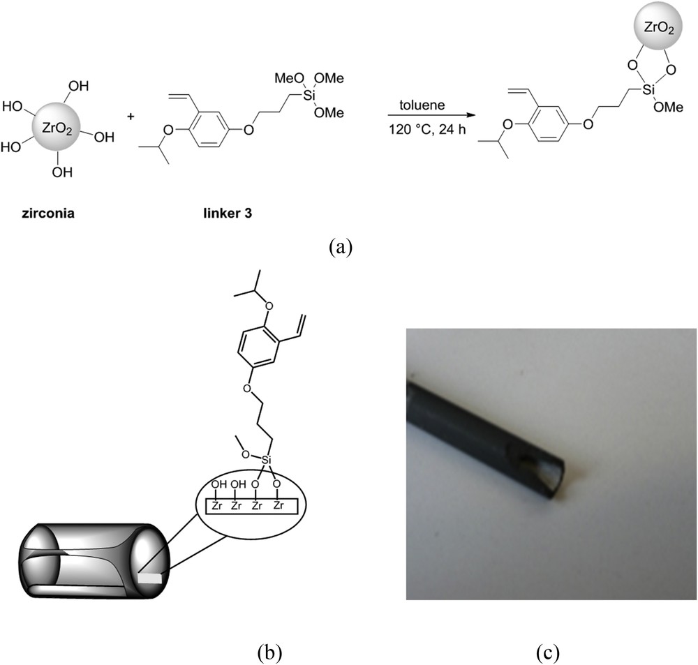
(a) Grafting procedure of zirconia surface, (b) grafting on the active layer of a tubular membrane, and (c) picture of a zirconia M5-Carbosep pristine membrane.

(a) Grafting procedure of the Grubbs II catalyst on the silylated zirconia surface and (b) obtained catalytic tubular membrane.
2.2 Two approaches to graft linker 3
From a practical point of view, the linker 3 was synthesized from 1 and the silane 2 as depicted in Fig. 4. Consequently, two different procedures can be proposed for the membrane preparation depending on the way chosen to graft the linker 3, either in one or two steps.
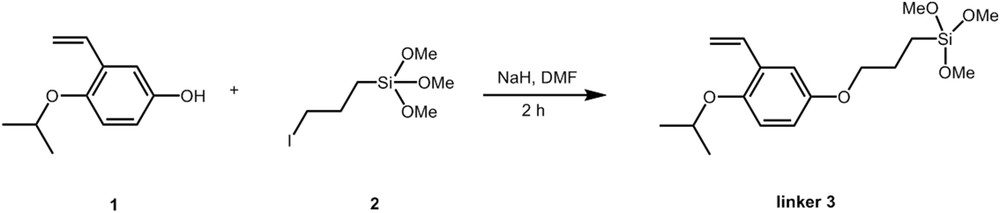
Preparation of silylated styrene linker 3.
In the one-step procedure, the direct grafting of linker 3 is achieved on the membrane according to the same protocol as those already used to graft silica or zirconia powder [61].
In the two-step procedure, grafting of linker 3 was obtained by first grafting the silane 2 as shown in Fig. 5. The modified surface was then treated with 1 in the presence of sodium hydride (NaH) (Fig. 6).
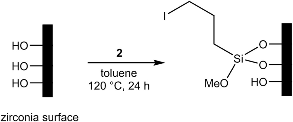
Grafting procedure of silane 2 on the zirconia membrane.
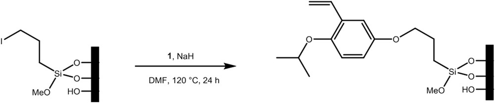
Grafting of 1 onto the silylated grafted membrane.
3 Experimental section
3.1 Reactants
All reactions were carried out under a dry argon atmosphere using standard Schlenk tube techniques. Toluene was freshly distilled over Na and THF over Na/benzophenone before use. DMF and dichloromethane were freshly distilled over CaH2 before use. Grubbs second-generation catalyst (further denoted Grubbs II, Fig. 1) was purchased from Sigma–Aldrich and stored under argon. 2,5-Dihydroxybenzaldehyde was purchased from Sigma–Aldrich and was used as received. (3-Iodopropyl)trimethoxysilane 2 was purchased from Sigma–Aldrich and was used as received. All other reagents were purchased from commercial sources and were used as received. Diallyltosylamide (DATA) was prepared according to a reported procedure [62].
3.2 Synthesis of intermediate compounds
3.2.1 Synthesis of 1
The synthesis of 1 was achieved according to the scheme depicted in Fig. 7. Compound 1 was obtained in four steps starting from commercially available 2,5-dihydroxybenzaldehyde. Compound 1 was isolated in 85% yield and was easily purified as determined from 1H NMR analysis (data not shown).

Synthesis of 1 and linker 3 according to Ref. [61].
3.2.2 Synthesis of linker 3
The synthesis of the silylated styrene linker 3 from Compound 1 was achieved as already reported in Ref. [61] (Fig. 7). Linker 3 was obtained in a 53% yield and a purity of 90% as determined by 1H NMR analysis. 1H NMR (200.12 MHz, CDCl3, 25 °C, TMS, δ (ppm)): 0.85 (t, 8.1 Hz, 2H, CH2); 1.31 (d, 6.0 Hz, 6H, CH3); 1.92 (m, 2H, CH2); 3.65 (s, 9H, CH3); 3.90 (m, 2H, CH2); 4.40 (sept, 6.1 Hz, 1H, CH); 5.20 (d, 10.1 Hz, 1H, CH); 5.71(d, 17.3 Hz, 1H, CH); 6.71–6.85 (m, 2H, CH); 6.90–7.15 (m, 2H, CH).
The main impurity was identified as remaining silane 2. Because of purification difficulty, the grafting solution was used as obtained and did not correspond to pure linker 3 even if the presence of silane 2 is not mentioned in the following for the preparation of the CM1 membrane (vide infra). This difficulty in the purification of linker 3 was one of the main reasons for developing an alternative two-step grafting procedure.
3.3 Zirconia powder and membranes
3.3.1 Zirconia powder
ZrO2 powder (P354, ca. 1 μm average size) was prepared from the same reactants as those used for the preparation of the active layer of the tubular membrane. This membrane, which is no longer produced, was kindly provided by Tech-Sep (now CTI Salindres, Saint-Maurice-de-Beynost, France) and used as received. The zirconia crystallographic lattice was cubic owing to stabilization provided by additives (confidential provider's data). The specific surface area of this powder was 64 m2 g−1.
Nevertheless, the specific surface area of the active layer of the UF membrane was certainly a little lower than that of the powder because of some differences in their respective thermal treatments (confidential provider's data).
3.3.2 Tubular inorganic membranes
Tubular zirconia membranes, M5-Carbosep, were kindly provided by Tech-Sep (now CTI) but are no longer commercialized. These UF membranes have an active layer made of zirconia on a carbon support and an Molecular Weight Cut-Off (MWCO) of 10 kg mol−1 corresponding to a pore diameter of ca. 6 nm (Fig. 2c). The external and internal diameters of this tubular membrane were 10 and 6 mm, respectively. The membranes used for the catalytic membrane preparation according to the dynamic protocol (vide infra) were of 200 mm length, whereas those for the immersion procedure were close to 25 mm length.
3.4 Membrane grafting
Grafting was performed according to two different procedures depending on the linker 3 grafting, either in one or two steps. In both cases, the final step consisted in the reaction of the Grubbs II precatalyst with immobilized linker 3 regardless of its immobilization procedure.
Preliminary tests aimed at checking that linker 3 grafting onto zirconia powder and the tubular membrane was obtained, regardless of its grafting route.
The direct grafting on zirconia powder was achieved by immersion in a solution of linker 3 followed by Grubbs II immobilization. Such protocol was checked step by step, and this material was used as reference (vide infra).
A second set of preliminary tests was performed to check that silane grafting (either linker 3 for the one-step protocol or silane 2 for the two-step protocol) can occur on the active layer of the tubular membrane in the same manner as for ZrO2 powder. The main difference between these two materials was attributed to the carbon support of the tubular membrane that could play the role of an adsorbent toward all organic compounds involved in the synthesis and could consequently lower the grafting ratio. This was checked by immersion of small membranes of 25 mm length in silane solutions followed by reaction of the immobilized silane either by 1 in the case of silane 2 grafting or by Grubbs II precatalysts in the case of linker 3 direct grafting.
A second procedure implemented under dynamic conditions was performed in a similar manner to filtration conditions. This procedure is aimed at proposing a scalable procedure for further possible industrial applications.
3.4.1 Direct grafting of linker 3 on zirconia powder by immersion
Grafting on zirconia powder was performed to have a reference powder material. Therefore, only one grafting procedure was implemented in that case. The pristine zirconia powder was dried for 24 h at 70 °C under vacuum. The modification was then carried out via direct grafting of linker 3 in a Schlenk tube maintained under an argon atmosphere. A total of 351 mg of dry zirconia powder was added at room temperature to a solution of 260 mg of linker 3 in 15 mL of dry toluene and refluxed for 24 h. The resulting white powder, further called P2, was then washed successively with dichloromethane, diethylether, and pentane. A portion of P2 powder was used for analyses and the other part was used for the next modification step. The final modification step was achieved in a Schlenk tube maintained under an argon atmosphere by a reaction of 20.9 mg Grubbs II precatalyst with 293 mg of P2-modified powder in refluxing CH2Cl2 (15 mL) for 12 h. After washing and drying, a final pale green powder was obtained, further denoted as CP3. Such color indicated the formation of the desired Hoveyda–Grubbs supported precatalyst.
3.4.2 Grafting of linker 3 in two steps on 25 mm membranes by immersion followed by Grubbs II immobilization
Four similar samples of about 25 mm length of the zirconia virgin membranes were used. The grafting of linker 3 on these membrane samples was obtained in two steps by grafting first silane 2 (Fig. 5) followed by reaction with 1 (Fig. 6).
A preliminary activation of the hydroxyl groups (−OH) of the zirconia surface was achieved with an alkaline solution. This alkaline pretreatment creates a strongly nucleophilic O−, which can then react with the silane 2. Alkaline pretreatment was performed by immersing the zirconia membranes in a NaOH solution (0.1 mol L−1) for 16 h. The four membrane samples were rinsed with water and dried in an oven at 120 °C for 8 h. One membrane (further considered as the pristine membrane) was kept as a reference, and the three other membranes were subjected to further modification steps (F1, F2, and CMF3).
The first step consisted in the reaction between the activated hydroxyl groups of the pristine zirconia and the methoxy groups of silane 2. The three membranes F1, F2, and CMF3 were soaked separately in 10 mL of dry toluene with 95.15 μL of silane 2 at 120 °C overnight. They were then washed successively with dichloromethane and diethylether. The F1 membrane was kept for analyses to check the grafting efficiency and only F2 and CMF3 membranes were subjected to the second modification step.
The second step consisted in an etherification reaction of the silylated grafted sample membrane with 1 in the presence of NaH. The F2 and CMF3 membranes were soaked separately in 1.5 mL of dry THF with 41 mg of 1 and 5.8 mg of NaH at room temperature for 16 h and were then washed successively with dichloromethane and diethylether. The F2 membrane was kept for analyses to check the second reaction occurrence.
The final Grubbs II immobilization was achieved on the CMF3 membrane in a Schlenk tube maintained under an argon atmosphere by soaking CMF3 in 20 mg of the Grubbs II precatalyst in CH2Cl2 (15 mL) at 40 °C for 12 h. The membrane was then washed with dichloromethane and diethylether and finally dried.
The direct grafting of linker 3 was not achieved on 25 mm membranes and was directly performed according to the dynamic procedure (see subsequently, CM1 membrane).
3.4.3 Grafting of tubular membranes in dynamic conditions
This dynamic procedure was implemented as a scalable protocol for further possible industrial purposes. Accordingly, we have considered that grafting in conditions close to cross-flow filtration could be achieved leading to a possible homogeneous modification of the active layer, thanks to the circulation of the grafting solution. According to such protocols grafting could occur on the membrane surface but also in the pores.
An original setup was developed by our laboratory for this dynamic grafting (Fig. 8). Two grafting procedures, detailed subsequently, were used for the elaboration of the tubular catalytic membranes.
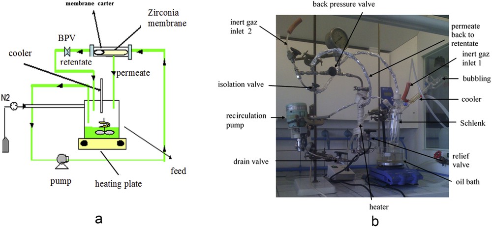
Experimental setup for dynamic grafting of the tubular membrane: (a) scheme; (b) picture.
3.4.3.1 Membrane conditioning common to the two dynamic grafting procedures
The first step of membrane conditioning was the same regardless of the following grafted ligand, either linker 3 or silane 2.
The 200 mm tubular membrane was first dried for 24 h in a desiccator under dynamic vacuum at room temperature to remove the molecular water adsorbed at the membrane surface. Alternatively, the membrane was dried in an oven at 80 °C or 100 °C for one night and cooled down to room temperature under vacuum in a desiccator.
The membrane was then mounted in the inox carter and installed on the pilot (Fig. 8). Dried toluene was then circulated in the membrane under a nitrogen atmosphere. During this membrane conditioning, nitrogen at 1 bar was continuously bubbled in toluene, and the transmembrane pressure (TMP) was close to 1 bar to have permeate and to carefully rinse the whole membrane structure.
The two routes for linker 3 grafting were implemented.
3.4.3.2 Dynamic direct grafting of linker 3
After the first conditioning step exposed previously, toluene was replaced by 100 mL of a 5.5 g L−1 toluene solution of silylated styrene linker 3. The grafting solution was circulated in the membrane tube at a low cross-flow velocity and a TMP of 1 bar for 13 h at 120 °C. The solution was allowed to naturally cool down to 30–40 °C while maintaining the circulation and the nitrogen atmosphere at 1 bar. The membrane maintained under a nitrogen pressure was successively rinsed with toluene, dichloromethane, and diethylether to remove the excess of linker 3 that could be adsorbed (and not grafted) on the membrane surface.
The final rinsing solvent (diethylether) was then replaced by dry dichloromethane that was circulated in the membrane under 1 bar nitrogen atmosphere for conditioning. The solvent was then replaced by 100 mL of the Grubbs II precatalyst dissolved in dry CH2Cl2 (400 mg L−1). The solution was circulated in the membrane tube for 10 h at 40 °C with a low cross-flow velocity and a TMP of 1 bar. The membrane maintained under nitrogen pressure was successively rinsed with CH2Cl2 and diethylether to remove the ungrafted precatalyst.
The catalytic membrane obtained according to this procedure was further called CM1. This membrane was stored in dry toluene before catalytic tests. After the olefin metathesis test, the membrane active layer was scrapped for analytical purposes (see subsequently).
3.4.3.3 Dynamic grafting of linker 3 in two steps
After the first conditioning step exposed previously, toluene was replaced by 100 mL of the grafting solution made of silane 2 at 5.5 g L−1 in 100 mL toluene. The grafting solution, in which nitrogen bubbling was maintained, was circulated in the membrane tube at a low cross-flow velocity and a TMP of 1 bar for 9 h at 114 °C. The solution was allowed to naturally cool down to 30–40 °C while maintaining the circulation and the nitrogen atmosphere at 1 bar.
The membrane was rinsed with toluene to remove the excess of silane 2 that could be adsorbed (and not grafted) on the membrane surface. The membrane was maintained in toluene overnight, then toluene was replaced by 200 mL of the grafting solution of 1. This solution was previously freshly prepared by pouring 535 mg of 1 dissolved in the minimum volume of diethylether in a 20 mL DMF suspension of 0.0781 g of NaH at 0 °C for 1 h before mixing with 180 mL of toluene. The solution was circulated in the membrane tube at a low cross-flow velocity and a TMP of 1 bar for 5 h at 120 °C. The membrane was then carefully rinsed with DMF.
DMF was then replaced by 180 mL of a solution made of 150 mg of the Grubbs II precatalyst in dry CH2Cl2 in the presence of 36 mg CuCl as phosphine scavenger. The solution was circulated in the membrane tube for 15 h at 40 °C with a low cross-flow velocity and a TMP of 1 bar. The membrane was then rinsed with CH2Cl2 to remove the ungrafted precatalyst.
The Grubbs II grafting step in DMF was repeated according to the same protocol to increase, if necessary, the grafting ratio. The catalytic membrane obtained according to this procedure was further called CM2. This membrane was then rinsed with toluene and stored in dried toluene before catalytic tests.
3.5 Olefin metathesis test
A model reaction of ring-closing metathesis of N,N-diallyltosylamide in toluene at 30 °C was used to evaluate the catalytic activities of the catalytic membranes and for sake of comparison of the free catalyst in solution (Fig. 9) [62].
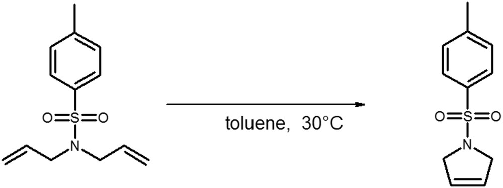
Model ring-closing metathesis reaction of diallyltosylamide (DATA).
From a practical point of view, catalytic tests were performed in the cross-flow loop of the same pilot as that used for the membrane grafting after a careful cleaning of the pilot and a first conditioning of the membrane in toluene. During the metathesis reactions the TMP was 1 bar and both retentate and permeate were collected over time.
The activity of the catalytic membranes was monitored according to two criteria: the final conversion of the substrate (Eq. 1) and the time to reach this conversion.
| (1) |
3.6 Analysis
3.6.1 Attenuated Total Reflection–Fourier transform infrared
Infrared (Fourier transform infrared [FTIR]) analyses allow us to evidence functional groups made of elements belonging to polar/polarizable bounds. FTIR analyses were performed using the attenuated total reflection (ATR) mode directly on powder obtained by scrapping of the active layer of the inorganic membrane, either initial or grafted one.
The spectra were recorded between 4000 and 600 cm−1 with a spectrometer provided by Perkin–Elmer (Spectrum 100, spectrum for windows software) equipped with a diamond crystal with an incidence angle of 45° allowing one reflection. The background spectrum was recorded in the air. Each spectrum was the result of 20 scans with a 2 cm−1 resolution.
3.6.2 Diffuse reflectance infrared Fourier transform
Diffuse reflectance infrared Fourier transform (DRIFT) is another infrared analysis allowing similar characterization as ATR-FTIR with a diamond crystal. Obtained spectra were close to those obtained with ATR-FTIR techniques, except some absorbance intensities more dependent on grinding with DRIFT than with ATR. Slight variations in the wavenumber location can also be observed between the two techniques.
DRIFT spectra were recorded directly on powders (that must be carefully grinded) slightly dispersed in KBr.
The spectra were recorded between 4000 and 600 cm−1 with a spectrometer provided by Perkin–Elmer (Spectrum 1000, spectrum for windows software) equipped with a DRIFT accessory. The background spectrum was recorded in the air with KBr powder. Each spectrum was the result of 20 scans with a 2 cm−1 resolution.
3.6.3 Liquid-state NMR
Liquid 1H NMR data were recorded on a Bruker DPX 200 spectrometer. Chemical shifts (δ) are given in ppm related to TMS and calibrated with residual nondeuterated solvent. Coupling constants are reported in Hertz (Hz); multiplicity of signals is indicated by using the following abbreviations: s = singlet, d = doublet, t = triplet, q = quartet, and b = broad.
3.6.4 Solid-state NMR
Solid-state NMR was used to evidence the grafting on a zirconia active layer of modified membranes. The modified zirconia powder was obtained by scrapping the internal part of the tubular (catalytic) membranes.
To evidence the grafting of organic compounds on zirconia, solid-state NMR spectra were registered with two different techniques. The magic angle spinning (MAS) was used for 1H solid-state NMR. MAS was coupled with cross polarization (CP) for 13C, 29Si solid-state NMR.
In both case, MAS-NMR and CP-MAS NMR spectra were recorded on a Bruker 300 spectrometer using acquisition parameters provided in Table 1.
Conditions for solid-state NMR according to the element.
| Nucleus | |||
| 1H | 13C | 29Si | |
| Technique | MAS | CP-MAS | CP-MAS |
| NMR frequency | 300 | 75 | 59.64 |
| Spinning rate (kHz) | 14 | 8 | 12 |
| Rotor size (mm) | 4 | 4 | 4 |
| Contact time (s) | – | 2 | 3.5 |
3.6.5 Inductively coupled plasma–optical emission spectrometry
The content of ruthenium in grafted powder was determined at the UMR-CNRS “Institut des sciences chimiques de Rennes” of the University of Rennes-1 by inductively coupled plasma–optical emission spectrometry (ICP-OES) analysis.
About 10 mg of modified zirconia powder was obtained by scrapping of the internal part of the tubular catalytic membranes. The scrapped powder was dissolved in 2% nitric acid. The Ru content was measured with a precision better than 0.02%.
3.6.6 Scanning electron microscopy–energy dispersive X-ray spectrometery
Scanning electron microscopy–energy dispersive X-ray spectrometery (SEM-EDX; microanalysis coupled with SEM) was used to evidence the different chemical elements present on the zirconia active layer of modified membranes, especially looking for Si and Ru each one being characteristics of a particular grafting step contrary to C that can be either because of 1, silane 2, linker 3, or Grubbs II, whereas Zr only imaged the zirconia. The modified zirconia material was obtained by scrapping the internal part of the tubular (catalytic) membranes.
Measurements were performed on a scanning electron microscope (JEOL JSM 6400, Japan) equipped with an ultrathin window energy dispersive X-ray spectrometer and a microanalysis system (LINK INCA Oxford Instruments, UK) allowing quantitative determination of elements. Results are expressed as atomic percentages with a precision better than 5 atom %.
3.6.7 Gas chromatography
DATA and c-DATA concentrations were determined from gas chromatography (GC) quantification with a Shimadzu GC gas chromatograph (GC-2014). The semicapillary column used was purchased from Supelco (Equity-5, 30 m × 0.53 mm × 1.5 μm film thickness). This column is mainly apolar, thanks to the stationary phase made of PDMS-PDPS (95-5). Injection achieved at 250 °C was followed by an analysis at a constant temperature set at 230 °C. The detection was obtained by an Flame Ionization Detector (FID) detector set at 250 °C. The carrier gas was nitrogen at 18 kPa. Quantification by the internal standard method was obtained with a precision of 1%. Consequently conversion ratio during metathesis was ±2%.
4 Results and discussion
4.1 Zirconia powder modification
Zirconia powder was only modified according to the first procedure starting by direct linker 3 grafting and followed by Grubbs II immobilization.
4.1.1 Direct linker 3 grafting
To evidence the effective grafting of linker 3, modified zirconia powder (P2) was analyzed by SEM-EDX and DRIFT. The presence of the linker 3 on this modified powder was confirmed by the detection of both C and Si. Confirmation of grafting was also provided by IR measurements. Indeed, comparison of DRIFT spectra of pristine and P2-modified zirconia powder highlighted the appearance of new bands located in three regions: 2900–3100, 1350–1750, and 800–1700 cm−1 (Fig. 10). Assignments of some of the new bands were proposed as follows: wavenumber (cm−1): 2974: ν(CH3, CH2) symmetric, 2937: ν(CH3, CH2) asymmetric, 1652: ν(C]C) styrene, 1452: ν(C]C) aromatic, 1387: δ (CH3), 1312: δ (CH2). Finally, the broad signal observed between −45 and −55 ppm in the solid-state 29Si CP-MAS NMR spectra also evidenced the grafting of linker 3 (Fig. 11). This broad signal results from the contribution of three different microstructures noted as T1, T2, and T3 corresponding to [–OSiR(OR′)2], [–O2Si(OR′)], and [O3SiR], respectively, with R = linker and R′ = OMe, OH [63].

DRIFT spectra of pristine and linker 3–modified (P2) zirconia powders.
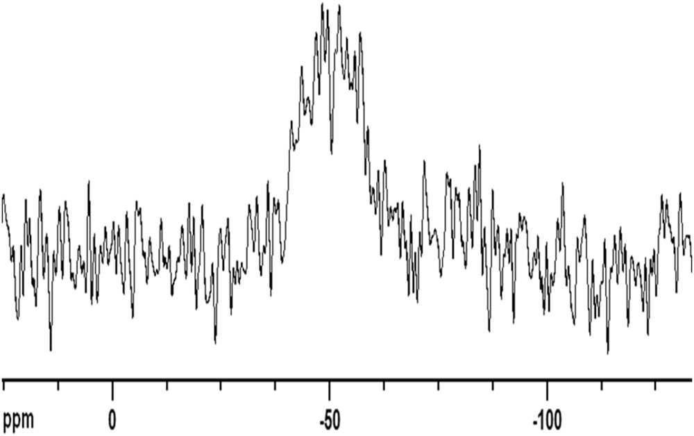
CP-MAS 29Si NMR of P2.
Fig. 12 shows the CP-MAS NMR 13C spectra on which the following assignments were proposed. 13C CP-MAS NMR: δ (ppm): 7 (CH2), 20 (CH3), 49 (O–CH3), 73 (CH, CH2), 110–119 (3CH aromatic, CH2 styrene), 126 (C aromatic, CH styrene), 135 (C aromatic), 137 (C aromatic).
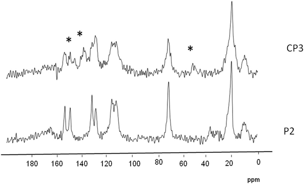
Solid-state 13C CP-MAS NMR spectra of the zirconia powder before (P2) and after (CP3) reaction with Grubbs II–∗new signals.
4.1.2 Grubbs II precatalyst immobilization
To evidence the effective immobilization of Grubbs II precatalyst on grafted linker 3, CP3-modified zirconia powder was analyzed.
SEM-EDX confirmed the presence of C and Si evidencing that a silane remained grafted to zirconia. However, it was not possible to detect ruthenium on CP3 powder probably because of the very small amount of Ru grafted and the detection limit close to 5 atom % for each element. However, ICP-OES analysis proved the effective presence of ruthenium on CP3-modified zirconia powder (Table 2).
Ruthenium content as determined by ICP-OES.
| Material | Ru (wt %) | Ru (mmol g−1) |
| CP3 (powder) | 0.209 | 2.07 × 10⁻² |
| CM1 (membrane) | 0.005 | 4.9 × 10⁻⁴ |
4.1.3 Catalytic test: ring-closing metathesis of DATA
The CP3 powder was evaluated in the catalytic test for sake of comparison with the catalytic membranes. A total of 106 mg of CP3 was used with a first single load of 80 mg DATA corresponding to 0.7 mol % of Ru to substrate ratio. A maximum conversion ratio of DATA into c-DATA was reached after 211 min at 30 °C (Table 3). A second cycle was achieved with a second load of the same amount of DATA highlighting a little decrease in the activity that was confirmed by a third cycle performed with a third load of the same amount of DATA.
Catalytic activity and multiple-use of modified zirconia in powder (CP3) and membrane form (CM1 and CM2).
| Cycle | Material | |||||
| CP3 | CM1 | CM2 | ||||
| Time (min) | Conversion (%) | Time (min) | Conversion (%) | Time (min) | Conversion (%) | |
| 1 | 211 | 97 | 92 | 5 | 90 | 12 |
| 2 | 240 | 88 | 210 | 15 | ||
| 3 | 392 | 54 |
4.2 Membrane modified by immersion: grafting of linker 3 in two steps followed by Grubbs II immobilization
This protocol was established by using four membranes of 25 mm length and was validated step by step to check that chemical reactions occurred as expected on the zirconia active layer of the membrane and that the porous carbon support was not a limitation (for instance massive adsorption of reactants not free to diffuse toward the active layer).
After alkaline activation, one pristine membrane was kept as a reference and the other membranes were subjected to further modification steps.
4.2.1 First step: grafting of silane 2
Three membranes (F1, F2, and CMF3) were grafted with silane 2 according to the experimental protocol explained previously. Among them, one membrane was kept for intermediate analyses and the two others were used for the next modification step.
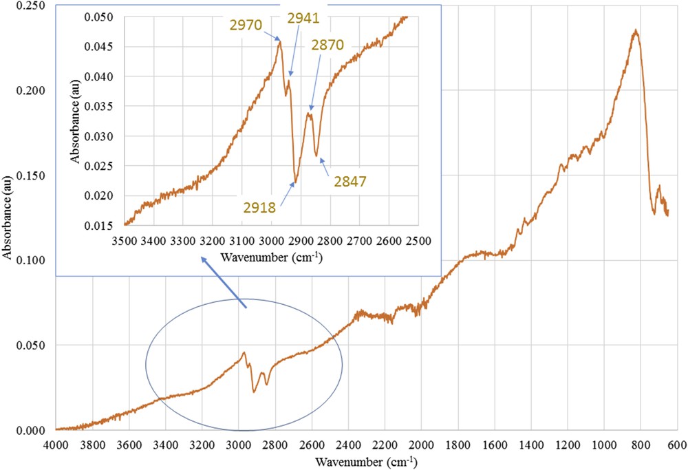
Fig. 13 compares the ATR-FTIR spectra of the unmodified and the silane 2-modified (F1) active layer scrapped on membranes. The ATR-FTIR spectra evidenced the presence of silane 2 onto a zirconia sample membrane through the alkyl groups bore by silicon as the modified membrane exhibited new bands located in two regions: 2800–2950 and 1200–1550 cm−1.
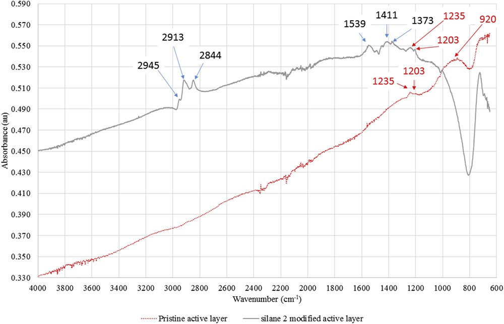
ATR-FTIR spectra of the active layers scrapped from the pristine zirconia membrane and the silane 2–grafted membrane (F1 membrane).
Two new adsorption bands around 2844 and 2913 cm−1 were assigned to ν(CH3, CH2) asymmetric and ν(CH3, CH2) symmetric of the alkyl groups of the silane, respectively.
An enlargement of the 1200–1550 cm−1 region showed the presence of four new absorption bands at 1203, 1373, 1411, and 1539 cm−1 corresponding to δ(CH2) and δ(CH3) of the silane alkyl groups, respectively.
4.2.2 Second step: grafting of 1
The two remaining membrane samples (F2 and CMF3) were subjected to another modification step by grafting 1 aiming at linker 3 final grafting.
Fig. 14 shows the ATR-FTIR spectra of the active layer of the F2 membrane successively modified by silane 2 and then 1. The 2800–2950 cm−1 region showed a modified absorption profile when compared to the F1 membrane that could be assigned to new ν(CH3, CH2) asymmetric and ν(CH3, CH2) symmetric. Moreover, modification of the absorption in the 1200–1550 cm−1 region showed the presence of three new absorption bands at 1238, 1477, and 1430 cm−1 corresponding to ν(COC), ν(CC) styrene, and ν(CC) aromatic, respectively.
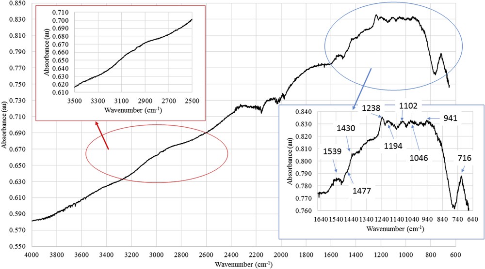
ATR-FTIR spectra of the active layers scrapped from the (silane 2 + 1)-grafted membrane (F2 membrane).
As such modification on the ATR-FTIR spectra before (F1) and after (F2) modification by 1 are quite subtle, the effective grafting of 1 (leading finally to linker 3 grafting) on the zirconia was more clearly evidenced by differences between raw spectra calculated according to Eqs. 2 and 3:
| (2) |
| (3) |
Fig. 15 shows the difference spectrum 1 determined from Eq. 2 allowing to evidence the presence of alkyl groups on the membrane.
Difference ATR-FTIR spectrum 1 between spectra of the active layers scrapped from the F2-grafted membrane (silane 2 + 1) and from the pristine zirconia active layer.
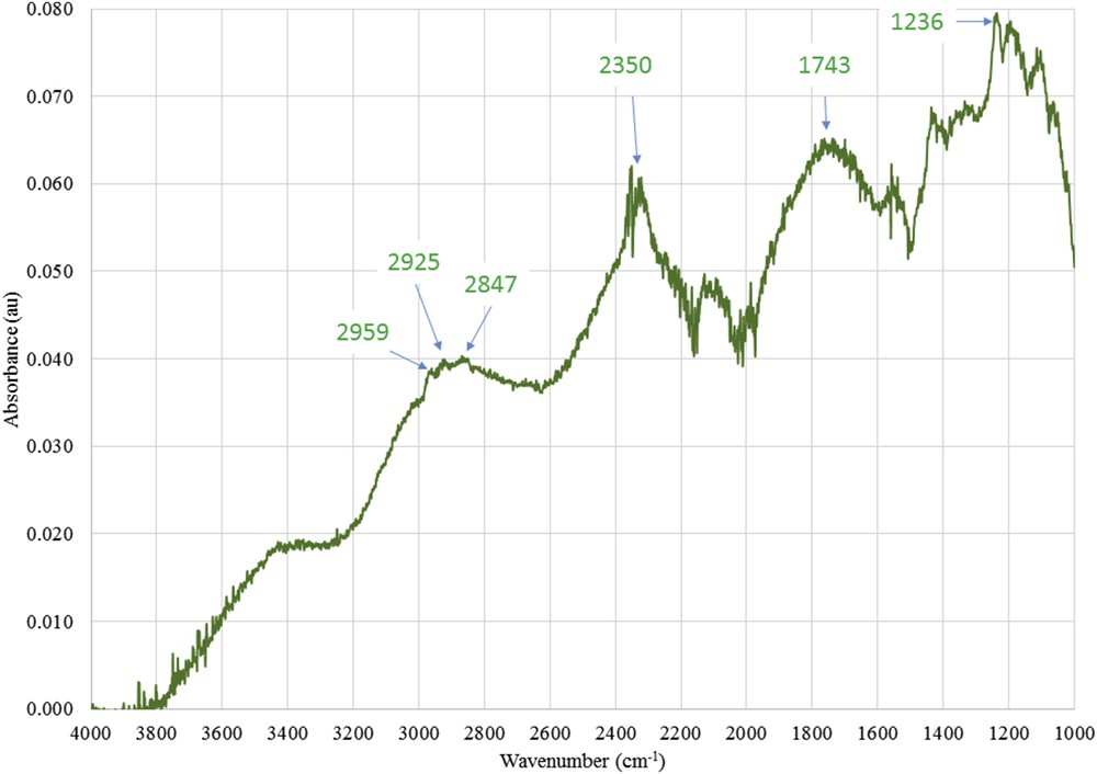
Fig. 16 shows the difference spectrum 2 determined from Eq. 3 allowing to evidence that alkyl groups on the F2 membrane were different from those grafted on the F1 membrane.
Difference ATR-FTIR spectrum 2 between spectra of the active layers scrapped from the F2-grafted membrane (silane 2 + 1) and the F1-grafted membrane (silane 2).
4.2.3 Final step: grafting of Grubbs II precatalyst
The remaining F2 membrane sample was subjected to the final modification step by grafting Grubbs II precatalyst leading to the expected catalytic membrane (CMF3).
ATR-FTIR failed at evidencing the grafting of the precatalyst probably because of the very small amount of the Grubbs II precatalyst grafted on the membrane. Nevertheless, the presence of ruthenium was detected by ICP-OES analysis of a scrapped active layer of the CMF3 membrane (quantification was not possible with sufficient accuracy).
4.3 Membranes modified according to the dynamic protocol
Two different grafting procedures were used to immobilize linker 3 onto the active layer of two 200 mm length zirconia tubular UF membranes either in one or two steps before the final immobilization of the Grubbs II precatalyst leading to a final catalytic membrane bearing a tailor-made prototype Hoveyda–Grubbs precatalyst of second generation.
4.3.1 Direct linker 3 grafting followed by Grubbs II precatalyst immobilization
Few analyses were achieved to prove the grafting on the tubular CM1 membrane as these analyses are destructive except the measurement of the catalytic activity.
Ruthenium quantification by ICP-OES proved the effective presence of the Grubbs–Hoveyda precatalyst and consequently the efficiency of the whole grafting scheme (Table 2), whereas SEM-EDX failed at showing the presence of Si (linker 3 grafting) and Ru (Grubbs II immobilization) because of the effective low grafting ratio. For the same reason, the CP-MAS 29Si solid-state NMR of the active layer of CM1 did not allow us to detect the signal of the covalent ZreOeSi, whereas the 1H NMR solid-state CP-MAS of active layer of CM1 could not really draw unambiguous information.
Despite the evidence for low grafting, the catalytic activity of the membrane was tested on the Ring Closing Metathesis (RCM) of DATA with an entire 200 mm membrane. Five percent conversion of DATA was reached in 92 min (Table 3). This result proves that a catalytic membrane was prepared even if performances were disappointing but in agreement with the low catalyst grafting suggested by analysis of the catalytic membrane.
4.4 Grafting of linker 3 in two steps followed by Grubbs II catalyst immobilization
Because of lengthy synthesis and membrane consumption by analysis procedures, we considered that the conversion of DATA in the ring-closing metathesis reaction was sufficient to prove the grafting of a metathesis catalyst. The catalytic activity of the CM2 membrane was thus tested on the entire 200 mm membrane and a load of 500 mg of DATA in 110 mL toluene. Under these conditions, 12% of DATA conversion was reached in 90 min (Table 3). The membrane was rinsed with toluene and a second cycle was initiated with a new load of 500 mg of DATA. A similar conversion of 15% was reached after prolonged reaction time, hence proving that the catalytic membrane was not deactivated after the first cycle. These results showed, for the first time, that such a sophisticated catalytic membrane can be prepared for olefin metathesis catalysis although the grafting ratio needs to be improved in the future.
4.4.1 Discussion
The CM2 membrane appeared better than the CM1 one but it is not possible to definitively draw that the two-step procedure applied for linker 3 grafting was better than the one-step procedure. Up to now, it appeared very difficult to identify the origin of such differences.
Performances of the catalytic membranes were less than that of the similarly modified powder certainly because of a low grafting ratio of the precatalyst on the membrane. This could be because of a greater specific area of the P354 pristine powder compared to that of the active layer of the UF M5-Carbosep membrane. Consequently, further modification improvements could be done on a nanofiltration membrane to increase this rate as its active layer might have a greater specific area because of thermal treatments at lower temperature during the active layer synthesis.
Moreover, the UF membrane flux to toluene was not significantly modified by the grafting when compared to the pristine zirconia membrane (and consequently probably the pore diameter remained constant), and no retention of DATA and c-DATA was observed and thus no selectivity between the substrate and the product of the olefin metathesis reaction. Using a nanofiltration membrane would allow us to induce a better selectivity between some substrate and associated products allowing a continuous extraction of the product from the reaction medium and not only a use of the catalytic membrane as a membrane reactive contactor.
5 Conclusion
The design and the grafting of the Hoveyda–Grubbs II precatalyst was developed according to two different grafting procedures depending on the silylated ligand grafted during the first modification step but leading, theoretically, to the same overall modified membrane. To the best of our knowledge, the catalytic membranes reported in this manuscript are the first examples of a Hoveyda–Grubbs II precatalyst type grafted onto the surface of a zirconia membrane. The catalytic activity of the “best” membrane was tested in two consecutive cycles of a model olefin metathesis reaction with no significant decrease in the substrate conversion. Although the overall protocol including the catalytic activity and the grafting ratio as well as the process setup and efficiency must be improved, the results obtained in the present study are innovative and promising as the concept of a catalytic membrane based on organometallic complexes was proved.
Acknowledgments
This study was financially supported by the French Ministry for Research (A.K., PhD), the ANR (ANR-09-CP2D-11-01, program NanoRemCat2), and “Rennes Métropole” (project UB453. 10ST422-01).
The authors acknowledge Francis Gouttefangeas from CMEBA of University Rennes-1 (http://www.cmeba.univ-rennes1.fr) for SEM-EDX analysis and Yann Le Gall and Maxence Moine for ICP-OES measurements.
Solid-state NMR spectra were acquired at the CRMPO (Centre régional de mesure physique de l'Ouest de l'université de Rennes-1, http://www.crmpo.univ-rennes1.fr), and the authors thank Dr. Marie Le Floch for her contribution and helpful discussions about solid-state NMR.
The authors thank Tech Sep/CTI for providing zirconia tubular membrane and zirconia powder. The authors also thank Frederic Bon (IUT Rennes–Université de Rennes-1) for discussions.