

1 Introduction
Isomorphous substitution of aluminium by iron is well known to occur both in natural and in synthetic microporous molecular sieves (zeolites) [1]. Incorporation of Fe into zeolite frameworks has been investigated both for better understanding the status of the trace amounts of ferric ions always present in natural zeolites and for synthesising the materials potentially useful for novel catalytic applications. Iron containing micro- and mesoporous molecular sieves show redox properties, which are responsible for their potential application in many oxidation processes (e.g. [2,3]) and in the selective catalytic reduction of NOx with hydrocarbons (e.g. [4–6]). It is a general agreement that the reducibility of iron active species plays a key role in the oxidation processes. It is influenced by various factors depending on the preparation methods as well as the atmosphere and pre-treatment temperature of the materials before the catalytic reaction. Based on ionic radii, one should predict the incorporation of Fe3+ (r = 0.063 nm) being favoured with respect to Fe2+ (r = 0.077 nm).
The preparation of Fe-containing molecular sieves was attempted adopting the classical hydrothermal procedure, with successful results achieved for a large number of medium and large-pore frameworks [1,7]. Most of the literature in this topic deals with MFI structure (e.g. [8–15]). However, the incorporation of Fe3+ into Beta [15–17], MOR [18], FAU [19], LTL [20], MTW [7], and other structures of zeolites [1] has been also reported.
The isomorphous substitution of Al3+ by Fe3+ has been proved for several zeolite framework types using various characterisation techniques (among others: EXAFS, ESR, Mössbauer, diffuse reflectance IR and luminescence spectroscopies, as well as theoretical studies) [1]. Fe3+ located in the zeolite skeleton is stable to reduction (easy reducibility is important in many catalytic oxidation processes). However, iron tends to be partially removed from the framework by thermal treatment especially under steaming conditions. This behaviour can be explained with the low tendency of this ion to attain the tetrahedral coordination. Framework Fe3+ confers mainly acidic properties whereas iron located in the extra framework positions reveals also redox character. Therefore, to obtain the oxidation properties of ferrisilicate molecular sieves the location of iron in the zeolite channels outside the skeleton is favourable.
Generally one can consider four locations of iron species in the molecular sieves (i) in the skeleton, (ii) outside the skeleton in the extra framework cationic positions, (iii) outside the skeleton in the channels as iron oxide species, (iv) outside the skeleton in the channels as organometallic complex.
The location of iron species in the extra framework positions of microporous molecular sieves (zeolites) can cause the diffusion limitation in the catalytic processes. Taking that into account one should look for more opened structures, like mesoporous molecular sieves, as supports for iron species. Since the discovery of mesoporous silicates at 1992 by Mobil Oil researchers [21] M41S family (MCM-41 and MCM-48) materials have been most often studied as supports for various transition metals [22]. The narrow controlled pore size distribution (PSD) in the ordered hexagonal MCM-41 and cubic MCM-48 materials (Mobil codes) and the large pore openings have added a new dimension to intrapore chemistry that had previously focused on microporous zeolitic materials [23].
However, one should stress significant structural differences between zeolitic and mesoporous molecular sieves of M41S family. First of all microporous zeolites are strictly crystalline with three dimensional translation symmetry, whereas mesoporous MCM-41 in fact are amorphous (they are built from amorphous walls located around mesoporous tubes). Crystallinity of MCM materials is related to the well hexagonally ordered mesopores giving rise to the appearance of XRD peaks at 2Θ < 7 deg region. The thickness of amorphous walls in MCM-41 varies depending on the preparation methods and metal element introduced during the synthesis together with silicon. In a consequence, metals introduced via cation exchange procedure can be relatively easy incorporated into the walls of MCM-41 and therefore can occupy both framework and extra framework positions. The distinction between both locations is not clear for MCM-41 contrary to ZSM-5 zeolites. The different localisation of iron in MCM-41 and ZSM-5 leads to various microenvironment of metal species which determines surface behaviour. Therefore, one can expect that the structural differences between ZSM-5 and MCM-41 materials will result in various surface and catalytic properties of iron-modified micro- and mesoporous molecular sieves. This behaviour is well illustrated by Stockenhuber et al. [24–26]. The authors stated that the main difference between FeZSM-5 and FeMCM-41 materials is the presence of Fe–O nanoclusters in FeZSM-5 which seem to be more active in the oxidation reaction than isolated irons entities in mesoporous materials [26]. It is worthy of notice that both types of materials, MCM-41 and ZSM-5, exhibit various amount of silanolic groups. The first one contains far more Si–OH species which participates in redox processes. All the mentioned differences between Fe-modified ZSM-5 and MCM-41 molecular sieves have to be taken into account in the consideration of surface and catalytic properties of iron species.
This paper reviews our studies concerning the incorporation of iron species in various positions of MCM-41 materials having various compositions (silicate – denoted MCM-41, aluminosilicate – AlMCM-41, and niobosilicate – NbMCM-41). Before we have started our investigations in this field there were some reports concerning the doping of MCM-41 with iron [27–29]. The aim of our study was the incorporation of iron to MCM-41 materials by various methods as well as the evaluation of iron states in various MCM-41 matrices and its catalytic behaviour [30–34]. The results will be compared with those obtained for iron-doped silica [30] and ZSM-5 [5,6]. The following procedures have been applied for location of iron species in MCM-41 samples: (i) incorporation of metal during the template synthesis [32,33], (ii) ion exchange (IE) [5,31], (iii) template ion exchange (TIE) [5,31], (iv) solid state (SS) IE (only for ZSM-5) [5,31], (v) wetness impregnation (imp. A) [30,32], (vi) wet impregnation (imp. B) [30], (vii) chemical vapour deposition (CVD) [6,30,32], and (viii) immobilisation of organometallic complex (ferroceneacetic acid (FAA)) [34]. The focus was on the following aspects: location and coordination of iron species (skeletal vs. extra framework), structure/texture changes after Fe-modification, reducibility of metal, strength of Fe-support interaction, oxidative and acidic properties of Fe species tested in the catalytic reactions and spectroscopic measurements.
2 Experimental
2.1 Catalysts preparation
2.1.1 Synthesis
For the preparation of MCM-41, AlMCM-41 and NbMCM-41 materials the classical hydrothermal synthesis in the polypropylene (PP) bottles has been applied [21,35] in case of the matrices used for FAA immobilisation and when iron was introduced during the synthesis. For all other cases the synthesis was performed at room temperature (adapted from paper of Schumacher et al. [36]). Both types of syntheses were carried out in the presence of cetyltrimethylammonium cations (CTA+) (Aldrich) from mixtures containing salts of aluminium or niobium and silica source.
In the hydrothermal synthesis the reactant mixture consisted of sodium silicate (27% SiO2 in 14% NaOH) (Aldrich) for MCM-41 material, and appropriate amount of aluminium sulphate (Polskie Oczynniki Chemiczne-Gliwice) and niobium(V) oxalate (CBMM, Brazil) for AlMCM-41 and NbMCM-41 materials, respectively. The ratios of Si/Al or Si/Nb in the gel were assumed as 32 or 64 or 128. The formed gel from these components was stirred for 0.5 h. Next, the pH was adjusted to 11, and distillate water was added. The gel was moved into a PP bottle and heated without stirring at 373 K for 24 h. The reactants were cooled down to RT in order to adjust pH again to 11. After this, the mixture was heated ones more to 373 K and left for another 24 h. The product was filtrated and washed with distilled water. After drying, the template was removed by calcination at 823 K (temperature ramp 5 K min–1), 1 h in helium flow and 15 h in air under static conditions.
Iron was incorporated into the mesoporous molecular sieves of MCM-41 type, containing or silicon, or both silicon and aluminium, or silicon and niobium, during the hydrothermal synthesis carried out according to the method described above. Iron(III) nitrate (Aldrich) was used as Fe source. The assumed Si/Fe ratio was 64 (e.g., FeMCM-41-64), 128 (FeMCM-41-128) or 256 (e.g., FeNbMCM-41-256).
Synthesis at room temperature of MCM-41, AlMCM-41, and NbMCM-41 was done in the following way: ethanol and aqueous ammonia were added to the surfactant solution – cetyltrimethylammonium chloride in water. The solution was stirred for 10 min and tetraethoxysilane – TEOS was added followed by aluminium sulphate or niobium(V) oxalate (depending on the desired product) solutions. After stirring for 2 h at room temperature the resulting precipitate was recovered by filtration, washed with distilled water and dried in air at room temperature. The template was removed by calcination at 823 K for 8 h.
The metal contents in the calcined samples were determined by inductively coupled plasma (ICP) emission spectroscopy after solubilisation of the samples in H2SO4/HNO3/HCl solutions.
2.1.2 Ion exchange (IE) [5,31]
The Fe IE was performed by stirring of the solid in aqua solution of Fe(NO3)3 (Aldrich) at 308 K for ZSM-5 (Degussa, Si/Al = 31) (6 h) and at 323 K for MCM-41, AlMCM-41, and NbMCM-41 (1 h). After stirring, the samples were filtrated, washed before drying at 393 K, and calcined at 773 K.
2.1.3 Template ion exchange (TIE) [5,31]
TIE was performed in the same manner as IE but the starting mesoporous material contained template (i.e. it was before calcination). The template was next removed via calcination at 823 K.
2.1.4 Solid state (SS) ion exchange [5,31]
The SS IE (applied only for ZSM-5 zeolite) was performed in the following way. The appropriate amount of FeCl2·4H2O (Aldrich) was mixed with 3 g of NH4ZSM-5 (prepared by NH4 cation exchange procedure) and heated in oven 3 h with the increase of the temperature to 823 K and next 6 h at 823 K.
2.1.5 Wetness impregnation (imp. A) [30,32]
The outgased silica or mesoporous material (673 K, 3 h in oven) was filled in with the appropriate amount (a volume of the solution ideally equal to the pore volume of the support) of an aqueous solution of iron(III) nitrate (Aldrich) and located in an evaporator flask where the catalyst was rotated and heated at 353 K for 1 h. The impregnated powder was dried at 393 K for 12 h and then calcined at 823 K for 4 h in oven.
2.1.6 Wet impregnation (imp. B) [30]
The outgased silica (673 K, 3 h in oven) was flooded with the appropriate amount (a large volume of the initial solution which was reduced on drying) of an aqueous solution of iron(III) nitrate (Aldrich) and shortly mixed. After that the mixture was heated at ~353 K, without stirring, for 8 h. Next water was evaporated during rotation at ~353 K for 1 h. The obtained powder was dried at 333 K for 8 h and then calcined at 823 K for 4 h in oven.
2.1.7 Chemical vapour deposition (CVD) [30,32]
In the CVD method FeCl3 (Merck) was used as a precursor of Fe species. FeCl3 was sublimed onto SiO2 or mesoporous molecular sieves under anaerobic conditions at 603 K for 3 h. Then the material based on SiO2 was washed with distilled water for reducing the amount of chloride ions. Finally, the catalyst was dried and calcined at 823 K in air flow for 4 h.
2.1.8 Immobilisation of FAA [34]
The simple method for immobilisation of FAA (Aldrich) has been applied. The introduction of FAA was carried out by immersing the solid material (1 g of silica or hydrogen form of mesoporous material) into 100 cm3 of toluene solution of FAA. The content of FAA molecules in the solution corresponded to the number of niobium (in NbMCM-41) or aluminium (in AlMCM-41) atoms in the material (Si/Al or Nb = 32). In the case of silicate MCM-41 or amorphous silica the concentration of the solution was the same as when AlMCM-41 was modified. The mixture was stirred at room temperature for 6 h. Next the solid was separated from the solution by filtration and washed with 200 cm3 of toluene. At the end the catalyst was dried at 353 K for 10 h.
2.2 Characterisation techniques
2.2.1 X-ray diffraction (XRD)
X-ray diffraction patterns were recorded on a TUR-62 diffractometer using Ni-filtered Cu Kα radiation (1.5418 nm). The XRD data were collected in the 2Θ-region of 1.4–10° with a step size 0.02°. They were also collected in the 2Θ-region of 10–60, in order to monitor the formation of new phases, if any.
2.2.2 Nitrogen adsorption/desorption
The surface area and pore volume of the materials were measured by nitrogen adsorption/desorption at 77 K using the conventional technique on a Micromeretics 2010 apparatus. Prior to the adsorption measurements, the samples were degassed in vacuum at 573 K for 2 h. Surface area was calculated by the BET method. The PSD, the pore size (the maximum of PSD) and the mesopore volume were determined from the adsorption isotherms using the corrected algorithm (KJS-BJH) based on the Barred–Joyner–Helenda (BJH) procedure [37].
2.2.3 Infrared spectroscopy (FTIR)
Two FTIR equipments have been used: Bruker Vector 22- and Nicolet Magna 550 spectrometers. The standard self-supported pellets of the materials (~5 mg cm–2) were placed in the vacuum cell and activated in two ways: (i) evacuation at 293 K for 6 h (Procedure I) and (ii) calcination under pure O2 at 723 K for 1 h, cooling to RT, evacuation of oxygen at RT, evacuation at 723 K for 7 h (Procedure II). Nitrogen(II) oxide was adsorbed at room temperature as probe molecule. Moreover, the adsorbed species was evacuated at various temperatures. All spectra were recorded at room temperature. The IR spectra of activated samples were subtracted from those registered after NO adsorption at RT followed by various treatments. The reported spectra are the results of this subtraction.
2.2.4 Electron spin resonance (ESR) spectroscopy
The ESR investigations were carried out using RADIOPAN SE/X 2547 spectrometer. A cavity operating at a frequency of 8.9 GHz (X-band) was used. The ESR measurements were performed at 77 K and RT. Before the registration of spectra, the catalyst was activated under vacuum in the temperature range of RT–973 K depending on the desired sample.
2.2.5 Temperature-programmed reduction (H2-TPR)
The temperature-programmed reduction of the samples was carried out using H2/Ar (10 vol.%) as reducing agent (flow rate = 32 cm3 min–1). The sample (0.03 g) was filled in a quartz tube, treated in a flow of helium at 723 K for 1 h and cooled to room temperature. Then it was heated at a rate of 10 K min–1 to 1300 K under the reducing mixture. Hydrogen consumption was measured by a thermal conductivity detector in the PulseChemiSorb 2705 (Micromeretics) apparatus.
2.2.6 Thermogravimetry
Thermogravimetry measurements were carried out in air atmosphere using SETARAM SETSYS-12 apparatus with temperature ramp 5 K min–1.
2.2.7 Transmission electron microscopy (TEM)
For TEM measurements powders were deposited on a gird with a holey carbon film and transferred to JEOL 2000 electron microscope operating at 80 kV.
2.3 Catalytic tests
2.3.1 Isopropanol decomposition [30,34]
Isopropanol decomposition was performed using a pulse micro-reactor and a helium flow of 40 cm3 min–1. The catalyst bed (0.05 g with a size fraction of 0.5 < ∅ < 1 mm) was first activated at 423 K (in case of FAA/mesoporous materials) and at 673 K (for all other samples) for 2 h under helium flow (40 cm3 min–1). The isopropanol conversion was studied at 473, 523, and 573 K using 5 μl pulses of isopropanol. The reactant and reaction products were analysed using CHROM-5 gas chromatograph on-line with micro-reactor. The reaction mixture was separated on 2 m column filled with Carbowax 400 (80–100 mesh) at 338 K in helium flow (40 cm3 min–1) and detected by TCD.
2.3.2 Methanol oxidation [30]
The reaction was carried out in a fixed-bed flow reactor. 0.02 g of the catalyst, with a size fraction of 0.5 < ∅ < 1 mm was placed in the reactor. The samples were activated in helium flow (40 cm3 min–1) at 723 K for 2 h, and next pretreated in a stream of O2/He gas mixture at 723 K for 0.5 h before each run. Some experiments were carried out without O2/He pretreatment. The reactant gas mixture of CH3OH/O2/He, molar ratio of ~3/6/31, was used with a total flow rate of 40 cm3 min–1. The reactor effluent was analysed using an on-line gas chromatograph (SRI 8610 GAS) with FID and TCD detectors.
2.3.3 NO decomposition and the reduction of NO with hydrocarbons [5]
The decomposition of nitric oxide was carried out in a glass flow-through reactor working at atmospheric pressure. The reaction conditions were as follows: 5 vol.% of NO in He was passed downward at a total flow rate of 10 cm3 min–1 through the reactor containing 0.1 g of ZSM-5 based catalysts, and 0.03 g of mesoporous molecular sieves – grain size 0.5 < ∅ < 1.0 mm. Various catalyst weights were used in order to keep the same volume of the samples. The catalysts were activated mainly at 673 and 723 K (and sometimes at other temperatures) in a helium flow (70 cm3 min–1) for 2 h before the reaction. A GC with a 13X molecular sieve + Porapak Q column working at 333 K was used for analysing of NO and the reaction products.
The reduction of NO with propene was conducted in the following conditions. The reacting mixture (0.4% of NO in He, 0.4% of propene in He and 1.2% of O2 in He) was passed through a quartz reactor filled with 0.1 g of Fe-ZSM-5 and 0.03 g of mesoporous catalysts. The total flow of gas was 26 cm3 min–1, GHSV = 7000 h–1. The reduction of NO was conducted at three temperatures: 623, 673, and 723 K. An on-line GC equipped with a 2 m column filled with 13X molecular sieves registered the reagents and products.
2.3.4 Hydroxylation and polymerisation of phenol [34]
The phenol polymerisation and hydroxylation with hydrogen peroxide was carried out in a glass flask equipped with a magnetic stirrer, a thermocouple, a reflux condenser, and a membrane for sampling. The process was performed in the liquid phase using distillate water as a reaction medium. The reaction conditions were as follows: the reaction temperature –333 K; the reaction mixture consisted of 13 g of phenol +8 g of water +0.2 g of the catalyst + ~30% aqueous solution of H2O2 (25 mol% in relation to phenol, dropwise addition for 1 h 40 min). The process was continued 1 h at 333 K after the admission of hydrogen peroxide. HPLC (Waters) was applied for analyses of the reaction mixtures at the following conditions: column – MACHEREY-NAGEL, Nucleosil 100-5; Protect-1.5 μm; L = 250 nm; diameter 4.6 mm; loop size –5 μl; temperature of the column – ~298 K (room temperature); UV detector.
3 Results and discussion
3.1 Catalysts – texture/structure characterisation
The catalysts used and summary of their preparation are presented in Table 1. The composition and the texture parameters of the catalysts used are given in Tables 2–5.
The catalysts used in this work and summary of the preparation procedures
| Catalysts | Preparation procedure | |
| Hydrothermal synthesis; assumed ratio of Si/Fe = 64, 128 or 256 (the last number in the symbols denotes this ratio); Fe/Al or Fe/Nb = 1 | Synthesis |
| Wetness impregnation from aqueous solution of Fe(NO3)3; impregnated powder was dried at 393 K for 12 h and calcined at 823 K for 4 h | Post synthesis modifications |
| Wet impregnation from aqueous solution of Fe(NO3)3; impregnated powder was dried at 333 K for 8 h and calcined at 823 K for 4 h | |
| CVD – FeCl3 was sublimed at 603 K for 3 h; next the sample was calcined at 823 K for 4 h | |
| IE from aqueous solution of Fe(NO3)3, after filtration and washing the solid was dried at 393 K and calcined at 773 K | |
| Template IE was done like IE, but without template removal before the procedure | |
| Fe-ZSM-5 (SS) | SS IE was done by mixing of the solid with FeCl2·4 H2O and heating at 823 K | |
| Immobilisation of FAA was performed by immersing and mixing the solid in toluene solution for 3 h and drying at 353 K for 10 h |
Characterisation of the catalysts in which iron was introduced during the synthesis or via impregnation and CVD [32,33]
| Catalysta | Si/Fe atomic ratio (assumed) | Si/Fe real atomic ratio (Fe wt.%) | Si/Al or Nb atomic ratio (assumed) | Surface area (BET) (m2 g–1) | Mesopore pore volume (KJS)b (cm3 g–1) | Pore diameter (KJS)b (nm) |
| Fe/MCM-41 imp. A | 30 | 30 (3.00) | – | 1160 | 0.78 | 3.33 |
| FeMCM-41-64 | 64 | 67 (1.34) | – | 1060 | 1.02 | 3.96 |
| FeMCM-41-128 | 128 | 128 (0.76) | – | 1090 | 1.08 | 3.94 |
| Fe/AlMCM-41 imp. A | 29 | 29 (3.00) | 32 | 1090 | 0.86 | 3.33 |
| Fe/AlMCM-41 CVD | – | 32 (4.20) | 32 | 970 | 0.66 | 3.09 |
| FeAlMCM-41-128 | 128 | 124 (0.72) | 128 | 1060 | 1.09 | 4.03 |
| FeAlMCM-41-256 | 256 | –(~0.5) | 256 | 1100 | 1.07 | 4.14 |
| Fe/NbMCM-41 imp.A | 28 | 28 (3.00) | 32 | 1060 | 0.88 | 3.33 |
| Fe/NbMCM-41 CVD | – | 29 (2.90) | 32 | 990 | 0.62 | 3.07 |
| FeNbMCM-41-128 | 128 | –(0.75) | 128 | 1040 | 0.99 | 3.95 |
| FeNbMCM-41-256 | 256 | –(~0.5) | 256 | 1040 | 0.98 | 3.98 |
a Fe with slash (example: Fe/MCM-41) denotes the post synthesis modification; Fe without slash stands for iron introduced during the synthesis.
b Calculated according to Kruk et al.'s [37] method.
Characterisation of the parent materials hydrothermally prepared and modified with FAA [34]
| Catalyst | Fe content (wt.%) | BET surf. area (m2 g–1) | Wall thickness (t) (nm)c | Mesopore pore volume (KJS)b (cm3 g–1) | Pore diameter (KJS)b (nm) |
| MCM-41 | – | 1130 | 0.77 | 1.04 | 4.15 |
| AlMCM-41 | – | 1050 | 0.69 | 1.14 | 3.95 |
| NbMCM-41 | – | 1080 | 0.77 | 0.95 | 3.63 |
| FAA/MCM-41 | 1.81 | 920 | 0.94 | 0.74 | 3.36 |
| FAA/AlMCM-41 | 1.96 | 990 | 0.86 | 0.81 | 3.35 |
| FAA/NbMCM-41 | 1.89 | 930 | 0.96 | 0.67 | 3.07 |
| FAA/SiO2 (573)a | 1.20 | 320 | – | – | – |
| FAA/SiO2 (673)a | 0.37 | 320 | – | – | – |
a Activation temperature of SiO2 before FAA immobilisation.
b Calculated according to Kruk et al.'s [37] method.
c ; ;
Characterisation of zeolites and mesoporous materials modified via cation exchange procedures [5,31]
| Catalyst | IE procedure | Si/Ta | Fe/Ta | Fe (wt.%) |
| Fe-ZSM-5 (IE) | IE | 31 | 0.30 | 1.0 |
| Fe-ZSM-5 (SS) | SS | 31 | 0.75 | 2.4 |
| Fe-MCM-41 (IE) | IE | – | – | 1.1 |
| Fe-MCM-41 (TIE) | TIE | – | – | 2.9 |
| Fe-AlMCM-41 (IE) | IE | 32 | 0.33 | 1.0 |
| Fe-AlMCM-41 (TIE) | TIE | 32 | 0.33 | 1.0 |
| Fe-NbMCM-41 (IE) | IE | 32 | 0.23 | 0.6 |
| Fe-NbMCM-41 (TIE) | TIE | 32 | 0.70 | 2.1 |
a T = Al or Nb in the framework.
Characterisation of silica modified via impregnation with iron (III) nitrate [30]
| Catalyst | Procedure of modification | Fe (wt.%) | BET surface area (m2 g–1) |
| SiO2 | 0 | 362 | |
| Fe/SiO2 (imp. A) 1.6 | Impregnation A | 1.6 | 342 |
| Fe/SiO2 (imp. A) 2.9 | Impregnation A | 2.9 | 345 |
| Fe/SiO2 (imp. B) 1.6 | Impregnation B | 1.6 | 347 |
| Fe/SiO2 (imp. B) 2.9 | Impregnation B | 2.9 | 331 |
| Fe/SiO2 (CVD) | CVD | 1.0 | 324 |
3.1.1 Iron introduced during the synthesis of mesoporous materials [32,33]
Iron is easily introduced into MCM-41 structure during the synthesis as evidenced from almost the same Si/Fe ratios in the gels (assumed values) and in the final materials (Table 2), independent of the nature of the T-elements (Si, or Si + Al, or Si + Nb).
All materials prepared with iron source added during the synthesis depict the nitrogen sorption isotherms of type IV in the IUPAC classification and show a distinct feature: a sharp capillary condensation step at a relative pressure of ~0.3–0.4. The examples are given in Fig. 1C. The absence of the hysteresis below p/p0 = 0.4 for all materials is an indication of uniform mesopores. The hysteresis loop is observed in the p/p0 range close to the saturation pressure (p/p0 = 0.9–1.0) and it is usually ascribed to the presence of macropores. However, it is overlapped by the additional uncommon type-H4 hysteresis in the range 0.5–1.0 p/p0 (Fig. 1C). The size of this hysteresis loop decreases in the following order: FeAlMCM-41-128 (100 cm3 g–1 STP) > FeMCM-41-64 (60 cm3 g–1 STP) > FeAlMCM-41-256 (55 cm3 g–1 STP—not shown in the figure) > FeNbMCM-41-128 > FeMCM-41-128 (10 cm3 g–1 STP—not shown in the figure). Lin et al. [38], on the basis of the analysis of TEM micrographs, assigned this hysteresis loop at p/p0 = 0.5–1 to extensive structural defect holes amid the nanochannels. These holes are irregular in shape and their size distributes between 5 and 30 nm. The incorporation of iron besides aluminium leads to a larger hysteresis loop than that formed in FeMCM-41 and FeNbMCM-41. This kind of the hysteresis loop is also indicated in Nb-containing samples without Fe (Fig. 1Ac) and this effect increases with Nb loading. However, the hysteresis loops in Fe-containing samples are higher than that in NbMCM-41.
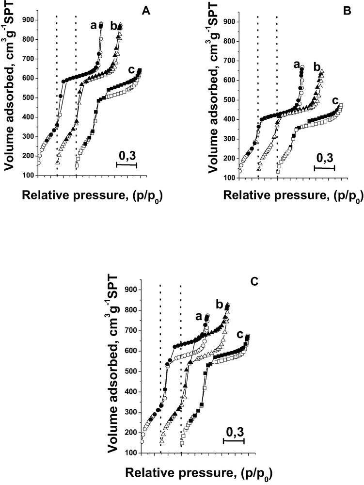
N2 adsorption/desorption isotherms at 77 K before (A) and after (B) immobilisation of FAA species on (a) MCM-41; (b) AlMCM-41; (c) NbMCM-41; and after incorporation of iron during the synthesis (C): (a) FeMCM-41-64; (b) FeAlMCM-41-128; (c) FeNbMCM-41-128.
The existence of defect holes does not interfere with the well ordering of the materials. The XRD low-angle patterns (Fig. 2C) show diffraction lines characteristic of mesoporous materials with well hexagonal ordered mesoporous structure of MCM-41 type in spite of defects determined by nitrogen adsorption/desorption isotherms. The XRD patterns are characterised by a narrow single peak (100) centred at 2Θ ≈ 2° and three well-resolved peaks in the range of 3–8°. The latter are due to the ordered hexagonal array of parallel mesoporous tubes and they are the best resolved for FeNbMCM-41-256. The shape of XRD patterns depends to some extent on the composition of the material. The content of iron and the nature of other T-elements (Si, or Al + Si, or Nb + Si) slightly influence the surface area and mesopore pore volume (Table 2). Pore diameter is also a little affected by the composition of the sample—the highest is when aluminium is present in the material.
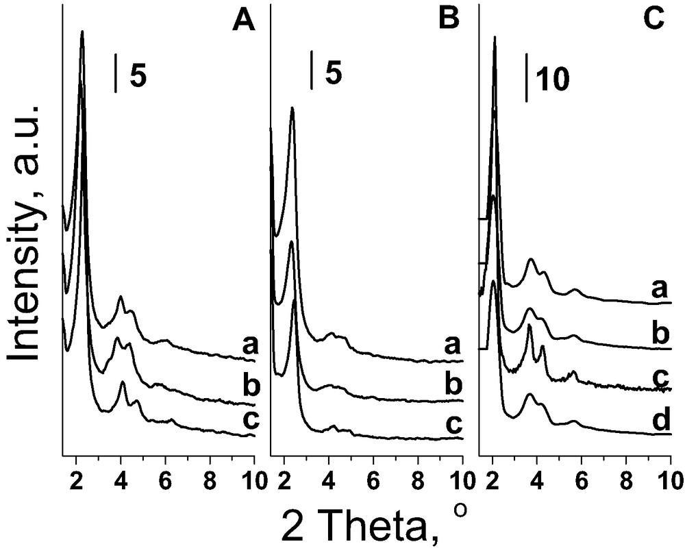
XRD patterns before (A) and after (B) introduction of FAA on: (a) AlMCM-41; (b) MCM-41; (c) NbMCM-41; and after incorporation of iron during the synthesis (C): (a) FeAlMCM-41-256; (b) FeAlMCM-41-128; (c) FeNbMCM-41-256; (d) FeNbMCM-41-128.
To conclude, the incorporation of Fe together with Al into silicate MCM-41 during the synthesis gives rise to the highest defected material, whereas the presence of Nb instead of Al in the gel used for the synthesis leads to the formation of very well ordered final materials.
3.1.2 Iron immobilised in mesoporous materials as organometallic complex [34]
The immobilisation of FAA on MCM-41 surfaces slightly influences the structure/texture parameters of these materials. XRD patterns are presented in Fig. 2A, B and are consistent with the X-ray powder diffraction patterns of silicate MCM-41 reported in the literature. After FAA immobilisation in all MCM-41 materials the XRD reflexes in the 2Θ = 3–8° region are less resolved than those in the parent samples suggesting or a partial loss in a long range order (Fig. 2B) [39] or rather a partial filling of mesopores with FAA. The latter case is confirmed by the broadening of reflexes at 2Θ ≈ 2° after FAA immobilisation.
The nitrogen adsorption/desorption isotherms shown in Fig. 1A, B are also of type IV in the IUPAC classification and exhibit a sharp capillary condensation step at a relative pressure of ~0.35. The sharpness of the steep rise is diminished as a result of FAA immobilisation. The hysteresis loop in the p/p0 range close to the saturation pressure (p/p0 = 0.9–1.0) is untouched after FAA modification. Contrary, the size of the other hysteresis loop in p/p0 = 0.5–0.9 range, characteristic of NbMCM-41 support, decreases after FAA incorporation. As discussed above this hysteresis loop is caused by the presence of the defect holes in the mesoporous material [33,38]. Recently [40], it has been found that niobium species are located in these defect holes. The change in the size of this hysteresis loop demonstrated in Fig. 1A, B suggests that FAA interacts with niobium species located in the holes.
The data calculated from N2 adsorption isotherms are shown in Table 3, also for modified silica. One can notice that in the case of mesoporous materials all textural parameters, excepting wall thickness, decrease after FAA incorporation. The BET surface area is still relatively high (920–990 m2 g–1) in FAA modified samples. The increase of the wall thickness indicates the immobilisation of FAA into the matrix. Based on these data one can conclude that FAA species are partially located in the mesoporous walls.
3.1.3 Iron located outside the skeleton of mesoporous materials as Fe-oxide species [30,32]
Wetness impregnation (imp. A) and CVD procedures were used in order to localise iron outside the skeleton of the mesoporous matrices (prepared at RT) in the form of Fe-oxide species. Prior to the impregnation SiO2 was outgased and next wetness and wet methods were used for the modification [30]. Transmission electron micrographs of silica impregnated by both techniques clearly indicated that wet impregnation (procedure B) leads to a better iron distribution than that obtained after wetness one (A) for low (1.6 wt.%) and higher (2.9 wt.%) Fe loading. However, besides that, only wetness impregnation has been applied in case of all mesoporous materials because wet method could lead to the partial IE process.
The XRD patterns of iron impregnated and CV deposited MCM-41 samples, presented in Fig. 3, are of pure quality in comparison with those shown in Fig. 2. However, it is worthy of notice that the broadening of XRD signals results from the filling of mesopores [41]. Fe-oxide species located outside the skeleton fills to some extent mesopores, which results in the changes in XRD patterns. The intensity of XRD lines is especially low for the materials prepared via CVD. It could be due to the formation of extra framework phase detected in the high angle XRD pattern at 2Θ about 33° and 36° (Fig. 3Bd). This phase was not detected on the other Fe modified MCM-41 samples and silica [30] prepared via CVD method.
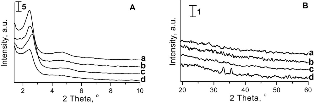
XRD patterns of (a) Fe/MCM-41 imp.A; (b) Fe/AlMCM-41 imp. A; (c) FeNbMCM-41 imp. A; (d) Fe/AlMCM-41 CVD in low (A) and high (B) angle-range.
CVD of iron species on MCM-41 materials (Table 2) [32] and silica (Table 5) [30] causes the decrease of surface area in comparison with the materials prepared via impregnation. Moreover, it diminishes the mesopore pore volume and pore diameter in MCM-41 materials. The latter parameters are also lower for the impregnated materials in comparison with those exhibited in case of the samples prepared with Fe-source (Table 2). The higher textural changes during CVD than those after impregnation are partially due to the higher temperature used in the first method.
3.1.4 Iron located outside the skeleton of mesoporous materials and zeolites in extra-framework cationic positions [5,31]
Four various matrices for iron cationic exchange have been used: microporous ZSM-5, mesoporous MCM-41, AlMCM-41, and NbMCM-41. Table 4 shows the composition of the materials obtained.
The TIE procedure leads to the higher level of Fe loading in mesoporous materials (with the exception of AlMCM-41) than the traditional IE technique. The SS IE applied in microporous ZSM-5 gives rise to the higher Fe content than that obtained after IE.
The hexagonal arrangement of mesopores is preserved after modification with iron as shown from N2 adsorption/desorption isotherms and XRD patterns. Only NbMCM-41 modified by the traditional IE procedure is characterised by low intensity XRD reflexes. It is most probably caused by the interaction of iron salt with niobium extra framework species which are formed during calcination used for the template removal.
Interestingly, the structure parameter of Fe-MCM-41 prepared by both methods (IE and TIE) (a0 = 47.227) is lower than that of parent silicate MCM-41 sample (a0 =51.004). Taking into account this fact and the ionic radius of Fe3+ (0.065 nm) and Si4+ (0.026 nm) one can assumed that the isomorphous substitution of Si4+ by Fe3+ does not occur during the cation exchange procedures and calcination because it should increase a0 parameter. The observed decrease of a0 is caused by the exchange of three sodium cations by one iron(III) cation.
3.2 Estimation of iron state in the catalysts
3.2.1 Iron introduced during the synthesis of mesoporous materials [33]
The reducibility of metal species has been a useful means for detecting the interactions between the metal and the support (skeleton). Temperature-programmed reduction with hydrogen was performed after activation of the calcined samples in helium flow at 673 K. Thus, it allows the characterisation of the materials pretreated in the mild reducing conditions.
The studies of Fe/SiO2 samples [30] indicated that for a high Fe loading (2.9 wt.%) three TPR peaks are well resolved (at 669, 759 and 842 K for the imp. B material and 668, 734, 842 K for the imp. A sample—symbols described in Table 1). The other catalysts exhibit only one TPR peak at 671 K–1.6 wt.% (imp. A) sample, 708 K–1.6 wt.% (imp. B) one, and 778 K–1 wt.% CV-deposited material. It has been postulated that the species on low iron loaded samples, which is generated after activation, is a form of iron oxide partially reduced (for instance Fe3O4). This species is further reduced with hydrogen only to Fe2+ even at temperatures as high as 1100 K. The difference in the reduction temperature of iron species in various samples allows the conclusion about the strength of its interaction with the surroundings. The fact that iron is reduced only to ferrous cations (not to metallic form) can be explained by the stabilisation of ferrous cations due to their strong interaction with the support. The same phenomenon has been described in the literature earlier for iron supported on alumina when the loading was very low (0.05%) [41,42].
In contrast, Fe/SiO2 materials with a higher Fe loading (2.9 wt.% of iron) prepared by both impregnation methods show three peaks on H2-TPR profiles as mentioned above. They were assigned to the three steps of iron oxide reduction: Fe2O3 → Fe3O4 → FeO → Fe. Such assignment is in agreement with the literature data, for instance for Fe-zeolite-beta catalyst [43]. The fact that the higher loading of iron causes easier the further reduction of ferrous cations by hydrogen to metal can be understood taking into account that unsupported iron oxide can be reduced to the zero-valence state at 673 K [44]. Generally, a higher concentration of cationic species makes their reduction easier.
The TPR profiles of mesoporous materials in which Fe was introduced during the synthesis are shown in Fig. 4 [33]. Only one TPR peak for all samples was registered. It is worthy of note that the amount of iron in these samples is between 1.34 and 0.5 wt.% (Table 2), i.e. lower than that for low iron loaded Fe/SiO2 described above. For siliceous MCM-41 material containing iron the maximum temperature of iron reduction is 737 K, not depending on the Fe content, whereas in aluminosilicate material the reduction temperature of Fe is only slightly higher. It is characteristic that the impregnated sample, denoted Fe/AlMCM-41, indicates the much easier reduction of iron (at the temperature of 50 K lower than that for FeAlMCM-41-128). Basing on this behaviour one can postulate the higher strength of Fe interaction with the other elements of matrices when iron is introduced during the templated synthesis. This can be treated as non-direct evidence for the incorporation of Fe into the skeleton of the mesoporous matrix because the discussed TPR peak was assigned above to the reduction of Fe3O4 tetrahedrally coordinated. So it can be also due to Fe tetrahedrally coordinated with oxygens in the mesoporous skeleton. This species is further reduced with hydrogen only to Fe2+ like in low loaded Fe/SiO2 [30].
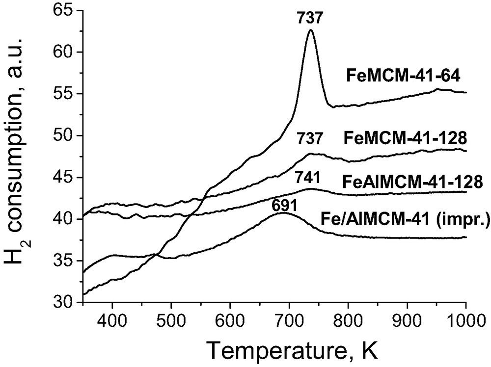
H2-TPR profiles of Fe containing MCM-41.
The ESR spectra of FeAlMCM-41 provided additional evidence for the Fe location in the skeleton [33]. They indicated the presence of a signal characterised by g = 4.26 typical of isolated Fe3+ paramagnetic cations in a strong rhombic distorted tetrahedral sites. Tetrahedral coordination of iron is also present in oxides (like Fe3O4 or gamma Fe2O3). However, iron in these oxides is not isolated and therefore gives another ESR signal than that registered for FeAlMCM-41.
3.2.2 Organometallic iron species immobilised in mesoporous MCM-41 samples [34]
The partially incorporation of iron species into the mesoporous walls has been postulated when immobilisation of FAA in mesoporous matrices was performed [34]. That was stated on the basis of FTIR and TG studies as well as the increase of wall thickness shown in Table 3.
FTIR spectra (Procedure I) allow us to conclude that hydroxyl groups participate in the immobilisation of FAA. It is demonstrated in Fig. 5 for FAA immobilised on silica. The spectrum of pure silica before FAA immobilisation presents one sharp band at 3747 cm–1, assigned to isolated terminal silanols, and two broad bands in the range of 3650–3400 cm–1 from hydrogen bonded silanol groups. The intensity of the latter bands depends on the activation temperature (Fig. 5Aa and Ba). The intensity of the hydroxyl band at 3747 cm–1 considerably decreases after modification of the support with FAA. This phenomenon can by explained by the chemical interaction of surface OH groups with FAA. It results in the growth of hydrophobic properties of the catalyst, important in many liquid phase oxidation processes. Similar results were obtained for mesoporous matrices. The participation of silanol groups in FAA immobilisation process is also supported by the impact of activation temperature of the matrix before FAA addition on the amount of iron in the final samples. The higher activation temperature of the support the lower amount of FAA is located in the final material (the example for silica is given in Table 3). The immobilisation of FAA on mesoporous MCM-41 type materials exhibiting very high surface areas is much higher than on silica. In the presence of Al or Nb in the support the hydroxyl groups bounded to these metal species or metallic cations take also part in the FAA immobilisation. This behaviour is considered below on the basis of FTIR study in the 1400–1800 cm–1 range.
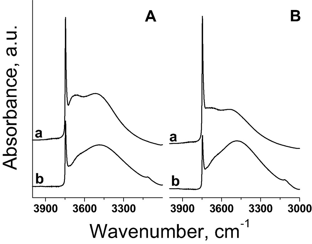
FTIR spectra recorded after evacuation for 6 h at RT before (a) and after (b) FAA incorporation on A) SiO2 (573); B) SiO2 (673) [34].
Besides the activation temperature, the nature of heteroatoms in mesoporous molecular sieves influences FAA immobilisation. The presence of Al or Nb in the mesoporous matrix favours the higher FAA coverage (AlMCM-41 > NbMCM-41 > MCM-41 from Table 3). Infrared spectra of the samples (pressed with KBr) allow the assumption the state of FAA adsorbed on MCM-41 materials. It has been evidenced that the free FAA complex shows, among others, two absorption bands at 1713 and 1434 cm–1 due to the asymmetric and symmetric ν(COO) stretching modes, respectively. They were not visible at the same positions in the IR spectrum of FAA/AlMCM-41. However, the spectrum of FAA immobilised on AlMCM-41 (not shown here) reveals two new, not well-resolved, bands in the 1450–1500 cm–1 region. They represent ν(COO) shifted to the other wavenumbers. Compared to the free FAA, a decrease of the energy between asymmetric and symmetric ν(COO) stretching modes is observed. This usually occurs in the case when the carboxylate groups are coordinated to a metal as a bidentate ligand.
The interaction of FAA with metal in the skeleton is also supported by the change in the size of hysteresis loop (Fig. 1A, B) in nitrogen adsorption/desorption isotherm of NbMCM-41 resulted from FAA immobilisation. This phenomenon is caused by the interaction of niobium species located in the defect holes [40] and FAA as described above.
3.2.3 Iron incorporated via impregnation and CVD [32]
Infrared spectroscopy combined with the adsorption of probe molecules (Procedure II) was applied in order to estimate iron species in impregnated mesoporous samples. It allows the differentiation between various iron species, located in the structure of mesoporous molecular sieves, which interact with NO molecules. We focus on the study of the spectra range characteristic for NO adsorption on transition metals [45].
Some of the obtained results are shown in Figs. 6 and 7 (more details are given in [32]). After NO adsorption on Fe-doped silicate MCM-41 prepared via different methods, spectra do not vary too much. The dominant band is located between 1822 and 1825 cm–1 and its wavenumber depends on the preparation procedure. The intensity of this band slightly increases with NO doses. According to [46], one can assign this band to Fe2+NO complex. Adsorption of a small amount of NO leads to the formation of 1905 cm–1 band (Fig. 6Aa). It is visible only for the sample prepared via impregnation. With the growth of NO amount adsorbed, that is covering this band from NO in the gas phase. The 1905 cm–1 band is probably due to the dinitrosyl complex formed on iron Fe2+ species [47]. One can expect the second band from this dinitrosyl at ~1840 cm–1. The intensive band at 1825 cm–1 (Fe2+NO) can cover that one at 1840 cm–1. In fact a shoulder on the left side of 1825 cm–1 band is visible. However, this shoulder is more pronounced when the sample is evacuated after NO adsorption (Fig. 6 spectrum e). Such evacuation causes the decomposition of dinitrosyl species and therefore, the shoulder in evacuated sample has to be assigned to some kind of mononitrosyl. One can propose the origin of this shoulder from Fe3+NO [48,49]. Thus the band (shoulder) at ~1840 cm–1 can be assigned to two kinds of species, dinitrosyl – Fe2+(NO)2 and mononitrosyl – Fe3+NO, and the interpretation depends on the presence of other bands in IR spectra.
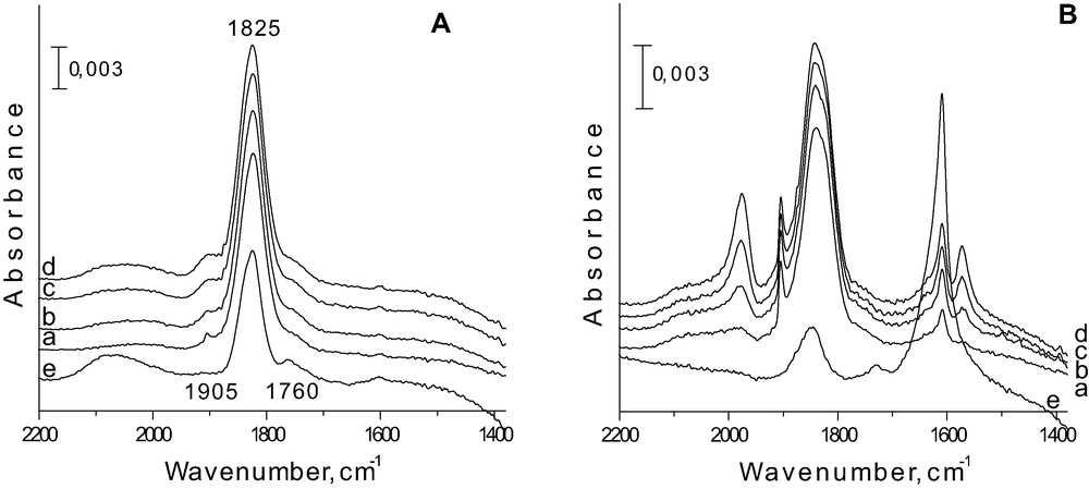
FTIR spectra after adsorption of NO on Fe/MCM-41 imp. A (A) and Fe/AlMCM-41 imp. A (B) (a) 10 Torr; (b) 20 Torr; (c) 30 Torr; (d) 40 Torr; and (e) after evacuation at RT [32].
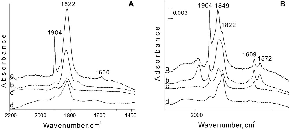
FTIR spectra after adsorption of 40 Torr NO on FeNbMCM-41 prepared by (a) CVD; (b) imp. A; (c) synthesis Si/Fe = 128; (d) synthesis Si/Fe = 256 (A) and on FeAlMCM-41 prepared by (a) CVD; (b) imp. A; (c) synthesis Si/Fe = 128; (d) synthesis Si/Fe = 256 (B) [32].
For aluminium containing samples the assignment of IR bands in this region is more clear (Fig. 6B). The IR bands at 1904 and 1849 cm–1 related to dinitrosyl formed on Fe2+ are well resolved. The best resolution of the discussed bands is noted on the material prepared via CVD of iron species (Fig. 7Ba), but is also well registered on Fe-impregnated AlMCM-41 (Fig. 7Bb). The formation of dinitrosyl requires isolation of iron species on which it is created. Thus one can conclude that the best isolation of Fe2+ is reached in AlMCM-41 matrix. Isolated Fe2+ ions can be obtained when they are stabilised on the surface and do not migrate during heating and evacuation. One can state that aluminosilicate AlMCM-41 matrix, showing negative charge of the skeleton, stabilises iron cations (Fe3+ in the calcined material, and Fe2+ after activation under vacuum).
Evacuation at room temperature leads to the appearance of the another mononitrosyl species (Fe2+NO) characterised by a band at 1760 cm–1. It appears after dinitrosyl decomposition because it is observed only when 1905 cm–1 band disappears and, therefore, one can conclude that it is formed on the same Fe2+ site, on which dinitrosyl was generated. It is worthy of notice that dinitrosyl is formed on the other Fe2+ species than that forming Fe2+NO characterised by the band at 1825 cm–1. Therefore, after dinitrosyl decomposition, new mononitrosyl, Fe2+NO, complex is formed (1760 cm–1) with participation of Fe2+ located in another environment than that forming 1825 cm–1 band.
Adsorption of NO on AlMCM-41 leads to the formation of mononitrosyl species on Al3+ cations, probably located in the extra framework positions (a band at 1973 cm–1). This band is accompanied by another one at 1575 cm–1, since their intensity changes simultaneously. Two other bands at 1609 and 1575 cm–1, are due to two different kinds of nitrates, bridging and bidenate, respectively [32].
IR spectra recorded after NO adsorption on Fe-doped niobium containing materials are similar to those observed for silicate ones (Fig. 7A). There is an exception for NO adsorbed on the sample prepared via CVD, which gives rise to the different IR spectra. For this sample the intensity of dinitrosyl band at 1904 cm–1 is much higher than for the other materials. However, the shoulder due to the second dinitrosyl band is not proportionally higher, indicating that 1904 cm–1 band does not origin only from dinitrosyl species. CVD can lead to the formation of iron oxide clusters, in which Fe2+–O–Fe3+ species are present.
The additional experiments performed on the reduced samples and described in [32] allow the suggestion that the origin of the 1840 cm–1 band is mainly from Fe3+, less from Fe2+(NO)2 (lack of 1840 cm–1 band after reduction in hydrogen).
Taking into account the above consideration and the fact that dinitrosyl species requires isolated iron cations, one can conclude a better dispersion (isolation) of iron species on AlMCM-41 matrix than on the others. Thus the discussed results indicate the role of the chemical composition of MCM-41 materials in the dispersion of iron cations. Moreover, the modification in the ratio of the intensities of bands at 1849 and 1822 cm–1 (Fig. 7B) stress the influence of Fe content on the species formed. The increasing amount of iron introduced by various methods to AlMCM-41 results in the increase of the band intensity at 1849 cm–1. It means that the higher Fe loading causes the localisation of iron species in the different coordination environment. This observation is in line with the results of ESR study described below.
All the Fe-doped samples prepared via impregnation or CVD depict cationic iron species isolated in the extra framework sites, Fe species in tetrahedron in the extra framework, and Fe2+–O–Fe3+ clusters. The relationship between their content depends on the chemical composition of MCM-41 samples, the Fe-doping procedure, and Fe content.
3.2.4 Iron located in the extra-framework cationic positions – prepared via Fe cationic exchange procedures [31]
Iron states in cation exchanged ZSM-5 zeolite and the mesoporous materials was determined on the basis of NO adsorption followed by infrared measurements and ESR study. The infrared studies were detailed described for impregnated and CV deposited Fe/mesoporous materials in the previous paragraph and therefore in this place the main focus is on ESR results.
The ESR experiments were conducted for the identification of the paramagnetic species on the surface of the catalysts used. The ESR spectra of Fe-ZSM-5 (IE) evacuated at 773 and 973 K and scanned at 77 K are shown in Fig. 8Aa, b. The results on zeolites are treated as reference for those obtained on mesoporous materials. The activation of Fe-ZSM-5 (IE) at 773 K leads to the appearance of two ESR signals (g = 4.26 and g = 2.003). The first signal (g = 4.26) is typical of Fe3+ paramagnetic cations in a strong rhombic distortion of the tetrahedral sites [50,51]. A narrow ESR signal (g = 2.003) can origin from coke formed from the residual template but also it can be due to Fe3+ in octahedral coordination as isolated ions at cationic positions [52]. Moreover, Chen et al. [50] attributed a sharp line at g = 2.0 to superoxide ions (O2–) which are associated with iron ions. The increase of the evacuation temperature to 973 K causes the appearance of a small signal at g = 6.23 assigned in the Refs. [50,53] to Fe3+ in the coordination of the less distorted tetrahedron. Moreover, a broad signal described by g ≈ 2.0 appears. It can be attributed to the Fe–O–Fe species with ferri-, ferro-, and/or antiferromagnetic behaviour [54]. This signal is better visible when the spectrum is scanned at RT (not shown here).
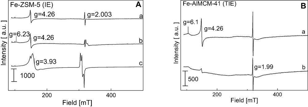
A. ESR spectra (registered at 77 K) of (A)—Fe-ZSM-5 (IE) after (a) evacuation at 773 K, 2 h, (b) evacuation at 973 K, 2 h, (c) adsorption 1 mbar of NO and evacuation at RT for 10 min; and (B)—Fe-AlMCM-41(TIE) after (a) evacuation at 873 K, 2 h, (b) evacuation at 973 K, 2 h [31].
The ESR spectra of Fe-AlMCM-41 (Fig. 8Ba, b) are similar to that of Fe-ZSM-5. The same signals are registered in the low field region (g > 3) which are attributed to isolated Fe3+ ions in different coordination environments, as well as lines at g < 3 originating from Fe-oxo species. However, the increase of the evacuation temperature to 973 K causes the decrease of the intensity of all the ESR signals showing that Fe3+ species in aluminosilicate mesoporous matrix are less stable than when they are located in microporous ZSM-5 zeolite.
Fig. 9A shows the ESR spectra of Fe-MCM-41 (TIE) material. They differ from those described above showing the domination of the signal at g = 2.2 and a very weak one from Fe3+ (g = 4.27) not visible in the scale used in this figure. These signals are visible after evacuation at 573 K but completely disappear when a higher evacuation temperature is applied (773 K). The above results allow us to propose that iron is not grafted to the silicate framework as Bourlinos et al. [55] observed in Fe-planted MCM-41 samples. A broad signal (g = ~2.2) can be assigned to some kind of iron-oxide species. Hagen et al. [52] observed a similar signal in H–[Fe–Al]–MFI samples and stated that they are due to aggregated hydroxide/oxide species, whereas Chen et al. [50] found a similar ESR line over Fe2O3/HMFI and attributed it to iron in small Fe2O3 particles. It is worthy of notice that all paramagnetic Fe3+ species disappear upon evacuation of the sample at 773 K, suggesting either the reduction of Fe3+ to Fe2+ or the formation of other iron ESR silent species.
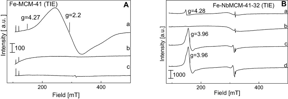
A. ESR spectra (registered at 77 K) of (A) – Fe-MCM-41 (TIE) after (a) evacuation at 573 K, 2 h, (b) evacuation at 773 K, 2 h, (c) adsorption of 1 mbar of NO and 12 h at RT and (B) – Fe-NbMCM-41-32(TIE) after (a) evacuation at 773 K, 2 h, (b) evacuation at 973 K, 2 h, (c) adsorption of 1 mbar of NO, (d) without any treatment after 12 h at RT.
Iron located in the mesoporous matrix containing niobium (Fe-NbMCM-41 (TIE)) gives rise also to a broad ESR signal at g = 2.10, due to a kind of Fe-hydroxide/oxide species (Fig. 9Ba, b). The participation of that Fe-oxo species in the whole paramagnetic Fe species is higher on Nb-containing matrix than on aluminosilicate one. However, two other species (g = 4.27 and g = 2.002), the same as registered on Fe-ZSM-5, are more pronounced. The evacuation at 973 K does not lead to the appearance of Fe coordinated in a less distorted tetrahedron (g = ~6) like on Fe-ZSM-5 and Fe-AlMCM-41.
Nitrogen oxide is a good probe molecule for the identification of Fe2+ isolated species if its adsorption is combined with the ESR measurements. The adsorption of NO on all the samples studied leads to the appearance of ESR signals in the range between 300 and 350 mT and another one in the low field (g = 3.93) – Fig. 8A, Fig. 9B. The latter origins from (NO)2 biradicals. The lines in the 300–350 mT region are not typical of mono or biradical of nitrogen oxide, i.e. a triplet from the hyperfine structure of N from NO or (NO)2. Most probably the superposition of ESR signals from mono, biradicals of nitrogen oxide and Fe-oxo species occurs. However, the fact that nitrogen oxide radicals appear after the adsorption on all the materials indicate the presence of Fe2+ isolated cations, but on Fe-MCM-41 their amount is negligible.
Taking into consideration the described above ESR results and the FTIR study reported in [31] one can estimate iron species in Fe-mesoporous materials in which iron was introduced via cation exchange procedure. The presence of Fe2+ isolated cations (ESR – mono- and biradicals of NO adsorbed on Fe2+, and FTIR – mononitrosyls Fe2+NO) was found in all materials studied, but their amount is negligible on Fe-MCM-41. The latter material exhibit the highest concentration of Fe oxide species and the lowest amount of tetrahedral coordinated Fe3+, both detected in all samples studied in [31].
3.3 Catalytic activity
3.3.1 Isopropanol decomposition
The isopropanol decomposition is a test reaction for the characterisation of acidic (Brønsted or Lewis) and/or basic/redox properties of the solids [56,57]. Dehydration of alcohol to propene and/or diisopropyl ether requires acidic centres, whereas the dehydrogenation to acetone occurs on basic or redox sites.
All the catalysts described in this paper were tested in the decomposition of isopropanol. The activity of the catalysts described in this paper depends on the reaction temperature and to some extent on the amount of iron in the samples and the composition of matrix. The highest conversion of isopropanol was reached on all Fe-doped AlMCM-41 samples indicating the role of matrix in the catalytic activity of Fe-containing materials. For the same type of matrix the activity is not simply related to the amount of iron. For example on AlMCM-41 support the following order of isopropanol conversion depending on the Fe-modification techniques can be drawn (in the whole 473–573 K temperature range):
CVD (2.9 wt.% Fe) > TIE (1.0 wt.% Fe) > IE (1.0 wt.% Fe) > imp. A (3.0 wt.% Fe) > synth. 128 (0.72 wt.% Fe) > synth. 256 (~0.5 wt.% Fe).
The selectivity of this reaction allows us to predict the nature of active sites in the materials studied. Independently of the nature of matrix the significant amount of acetone (>50% selectivity) in the reaction products was detected only on the samples prepared via immobilisation of FAA. All other materials showed the domination of isopropanol dehydration to propene, which occurs on acidic centres (Brønsted, or Lewis, or pairs Lewis acid–base). The FTIR measurements did not indicate the presence of acidic OH groups and therefore one can state the presence of Lewis acid sites on the catalysts studied, which can be active in the redox processes.
3.3.2 Oxidation of methanol
The redox versus acidic activity can be more precise studied in the oxidation of methanol. This reaction allows the discrimination between surface acid sites, formation of dimethyl ether (CH3OCH3), surface redox sites, formation of formaldehyde (HCHO) and methyl formate (HCOOCH3), and surface basic sites, formation of CO + CO2. Oxidation of methanol has been already applied for instance in the characterisation of niobium oxide catalysts modified with various components [58,59].
The same catalysts, which were used in the isopropanol test, were also studied in the oxidation of methanol. The samples in which iron was introduced during the synthesis with exception of FeMCM-41-64 were inactive under the reaction conditions applied in this work. FeMCM-41-64 indicated very low activity at the beginning of the process and then the activity diminished very fast with time on stream. On the materials prepared via CVD, impregnation, and cation-exchange procedure dimethyl ether and formaldehyde were observed in the reaction products with the domination of the latter. The amount of CO + CO2 was negligible. Taking into consideration these results one can conclude the overwhelming redox activity of these catalysts.
Contrary to the results obtained in the isopropanol decomposition, the higher Fe loading the higher methanol conversion was registered like it was observed in the case of Fe doped silica [30].
The results of methanol oxidation compared with those of isopropanol decomposition clearly shows that in the absence of oxygen in the reagent flow (i-PrOH decomposition) Lewis acid centres determine the reaction route, whereas redox route is catalysed by the same samples in the presence of oxygen (methanol oxidation).
3.3.3 NO decomposition and selective catalytic reduction of NO [5]
The results of NO decomposition are presented in Table 6. The microporous materials were activated before the reaction at 673 K and mesoporous one at 723 K. The activation temperature was chosen on the basis of the preliminary experiments which allow us to find the optimum activation conditions.
The activity of Fe cation-exchanged samples in the decomposition of NO
| Catalyst | Fe (wt.%) | Temperature of maximum activity (K) | NO conversion (%) | TOFa × 10–3 s–1 |
| Fe-ZSM-5 (IE)b | 1.0 | 673 | 10.0 | 2.00 |
| Fe-ZSM-5 (SS)b | 2.4 | 723 | 12.6 | 1.07 |
| Fe-MCM-41 (IE)c | 1.1 | 623 | 3.4 | 2.08 |
| Fe-MCM-41 (TIE)c | 2.9 | 623 | 2.3 | 0.55 |
| Fe-NbMCM-41 (IE)c | 0.6 | 523 | 3.4 | 3.84 |
| Fe-NbMCM-41 (TIE)c | 2.1 | 573 | 3.6 | 0.93 |
a TOF: number of NO molecules converted per Fe ion per second.
b The samples activated at 673 K.
c The samples activated at 723 K.
The mesoporous materials containing iron (prepared via cation exchange) reveal lower conversion of NO than that on both Fe-ZSM-5 catalysts. However, the TOF number for many mesoporous catalysts is comparable and even higher than that for both zeolites. Among mesoporous samples the materials containing niobium in the framework reveal the highest activity, and the temperature in which this activity is reached is the lowest (523 and 573 K).
The results of the NO selective catalytic reduction with propene (HC-SCR) carried out at 623, 673 and 723 K are shown in [5]. Fe-MCM-41 (TIE) material is completely inactive in the reduction of NO and only the oxidation of propene on this sample was registered. The activity of Fe-ZSM-5 (IE) and Fe-NbMCM-41 (TIE) in the NO conversion to N2 was the highest at 673 K. It is worthy of notice a great difference between the conversion of NO to N2 and the conversion of propene on Fe-ZSM-5 (the first being much higher). This difference is much lower on Fe-NbMCM-41(TIE) but at a higher temperature the unwanted formation of N2O takes place. It has been postulated that the reaction occurs via the oxidation of NO to NO2 and Nb (in NbMCM-41 matrix) can play a significant role in this process.
Iron impregnated mesoporous materials as well as the catalysts in which iron was introduced during the synthesis were inactive in the SCR of NO with propene. This behaviour supports the significant role of cationic iron species in this process.
3.3.4 Hydroxylation/polymerisation of phenol [34]
This process was performed in the liquid phase (water as the reaction medium) and hydrogen peroxide was applied as an oxidant. The results are reported in [34]. FAA/mesoporous materials reveal a very high phenol conversion (>96 wt.%) but the selectivity to hydroxylated products is negligible. It is caused by too fast decomposition of H2O2 by iron active species. This species indicates very high polymerisation activity. It has been indicated that the types of polymers formed are determined by the nature of the mesoporous support applied for FAA immobilisation.
4 Summary
Three fundamental features of Fe doped mesoporous MCM-41 materials have been considered in this paper: i) structure, ii) iron state (coordination, oxidation level, reducibility), and iii) catalytic activity. Their dependence on the nature of matrix (silicate MCM-41, aluminosilicate AlMCM-41, and niobosilicate NbMCM-41) and the methods of iron introduction (during the synthesis, immobilisation of FAA, CVD, impregnation, TIE, IE) are shown.
Hydrothermal synthesis in the presence of iron source creates defect holes in the final material, however, it does not influence the hexagonal order of the samples. The highest quality of the samples is reached when iron is introduced together with niobium and silicon into mesoporous materials. The distortion in the hexagonal order can be postulated for the samples in which iron is incorporated by the impregnation and CVD. However, one cannot exclude that the filling of pores with iron species does not disorder the material but causes the broadening of the XRD reflexes.
Tetrahedrally coordinated Fe3+ located in the skeleton of the materials in which iron was introduced during the synthesis is more difficult reduced than iron species formed after impregnation, CVD, or cation exchange. The latter procedure generates the easiest reducible iron species. In the mild reducing conditions (activation under vacuum or in helium flow) Fe3+ cations are reduced to Fe2+ in imp., CVD, TIE and IE modified samples. The best isolation of iron cations is reached on AlMCM-41 matrix thanks to the negative charge of the skeleton and its interaction with iron cationic species. CVD leads to the formation of iron clusters, in which Fe2+–O–Fe3+ species are present. The participation of Fe-oxo species in the whole paramagnetic iron forms is higher on Nb-containing matrix than on aluminosilicate, but it dominates on Fe doped silicate MCM-41. Generally, in all post synthesis modified samples (excluding FAA immobilised materials) the presence of isolated iron cations was found, but their amount is negligible on Fe doped MCM-41. FAA immobilisation causes the strong anchoring of organometallic species into the mesoporous walls.
Iron introduced into the skeleton of mesoporous materials is not active in the redox processes and its acidic activity in isopropanol dehydration is the lowest among all Fe doped samples (excluding FAA immobilised materials). CVD, imp., and cation-exchanged samples proved the redox properties in the gas phase oxidation of methanol. However, the reducibility of iron in the impregnated materials is not sufficient for its activity in the selective catalytic reduction of NO with propene. For this reaction the catalyst prepared via cation-exchange procedure is necessary. Interestingly, Fe-NbMCM-41 sample appeared to be attractive for NO SCR with propene and together with the other IE modified materials in the decomposition of NO. Finally, the polymerisation activity of FAA immobilised mesoporous samples should be stressed.
Acknowledgements
The authors appreciate Dr. Izabela Nowak’s and Anna Lewandowska’s excellent work in the preparation of a part of mesoporous matrices and I. Nowak for calculations of texture parameters from nitrogen sorption isotherms. Professor Marco Daturi (ISMRA, Caen, France) is acknowledged for his invaluable contribution in IR studies. Polish Ministry of Scientific Research and Information Technology (grant No 3T09A 096 26 2004-2005 and 3T09A 100 26, 2004-2007) is acknowledged for financial support.