

1 Introduction
An attractive and cheaper approach for the conversion of solar light into electrical energy has been to utilize large-band-gap oxide semiconductors such as TiO2 to absorb solar light [1]. Dye sensitization of large-band-gap oxide semiconductors has been investigated for many years [2–4]. In the 1990s a major photoelectrochemical solar cell development was obtained with the introduction of fractal thin film dye-sensitized solar cells devised by O'Regan and Grätzel [5]. In this solar cell, a monolayer of dye is attached to the surface of nanocrystalline TiO2 film. Photoexcitation of the dye results in the injection of an electron into the conduction band of the oxide. The original state of the dye is subsequently restored by electron donation from a redox system, such as the iodide/triiodide couple. The complexity of the TiO2 electrode with its large surface area has thwarted a detailed understanding of DSC mechanisms. This is the main reason why the energy conversion efficiency of DSCs has scarcely improved during the last decade.
On the other hand, the mechanism of conventional solar cells is well understood by way of equivalent circuits, which are considered to be useful tools to analyze cell devices and improve cell performance [6]. Therefore, it is necessary to obtain DSC equivalent circuits to accelerate the development of practical DSC-based photovoltaic modules. Recently, electrochemical impedance spectroscopy (EIS) has been used to analyze internal resistance in DSCs, and at least three internal resistances have been found [7–11]. However, as a result of the difficulty of fabricating stable and high-performance DSCs, equivalent circuit models of DSCs have not yet been established to the extent of those for conventional solar cells.
In a previous paper, we investigated the internal resistance of dye-sensitized solar cells through electrochemical impedance spectroscopy measurement as a means of researching DSC mechanisms, and constructed the equivalent circuit of DSCs based on analysis of results of the EIS [12]. In this paper, we examine in detail the internal resistances of a DSC using electrochemical impedance spectroscopy. The dependence of each internal resistance element on applied bias voltage is characterized and an equivalent DSC circuit is proposed. Efficient DSCs sensitized with bis(tetrabutylammonium)cis-bis(dithiocyanato)bis(4,4′-dicarboxylic acid-2,2′-bipyridine)rutherium(II) (N719 dye) and tris(tetrabutylammonium)tris(dithiocyanato)(4,4′,4′′-tricarboxy-2,2′:6′,2′′-terpyridine) rutherium(II) (black dye) are constructed by optimizing the internal resistances of DSCs.
2 Experimental section
Porous TiO2 electrodes of about 12- and 30-μm-thick films on a transparent conducting oxide (TCO) were prepared using a published procedure [13]. The TCO with different sheet resistance was prepared by controlling the thickness of TCO in the deposition process. The heated electrodes were treated with 40 mM TiCl4 aqueous solution at 70 °C for 20 min in order to make a good mechanical contact between the TiO2 particles and also conducting glass matrix. After sintering at 500 °C and cooling to about 80 °C, the TiO2 electrodes were dye-coated by immersing them into dye solutions at room temperature for overnight. An ethanolic solution of 0.4 mM cis-bis(dithiocyanato) bis(4,4′-dicarboxylic acid-2,2′-bipyridine)rutherium(II) (N3 dye) was used for dye adsorption. Dye solutions of 0.4 mM bis(tetrabutylammonium)cis-bis(dithiocyanato)bis(4,4′-dicarboxylic acid-2,2′-bipyridine)rutherium(II) (N719 dye) and 0.2 mM tris(tetrabutylammonium)tris(dithiocyanato)(4,4′,4′′-tricarboxy-2,2′:6′,2′′-terpyridine) rutherium(II) (black dye) were prepared in t-butanol/acetonitrile (1:1). The presence of 20 mM deoxycholic acid, as a co-adsorbent, in the dye solution of black dye is found to be necessary to prevent aggregation of the dye molecules on TiO2 film. Platinum-coated conducting glass was used as a counter electrode. The roughness factor (RF) of the platinum counter electrodes is defined as the ratio of an actual surface and effective surface to the projected area of the electrodes. The Roughness factor of platinum counter electrodes was measured by an atomic force microscopy (AFM) (Digital Instruments, Nanoscope IIIa), and the projected area was measured using optical microscope. The composition of electrolyte solution was 1,2-dimethyl-3-propyl imidazolium iodide (0.6 M), lithium iodide (0.1 M), iodine (0.05 M) and 4-tert-butylpyridine (0.5 M) in acetonitrile. Photoelectrochemical properties were measured using a digital source meter (Keithley Instruments Inc., Model 2400) under air mass (AM) 1.5 simulated solar illumination at 100 mW/cm2 [14]. The electrochemical impedance spectra were measured with an impedance analyzer (Solartron Analytical, 1255B) connected with a potentiostat (Solartron Analytical, 1287) under illumination at 100 mW/cm2 using a solar simulator (Wacom, WXS-155S-10). EIS spectra were recorded over a frequency range of 10−2–106 Hz at 25 °C. The applied bias voltage and ac amplitude were set at open-circuit voltage (Voc) of the DSCs and 10 mV, respectively. The electrical impedance spectra were characterized using Z-View software (Solartron Analytical).
3 Results and discussion
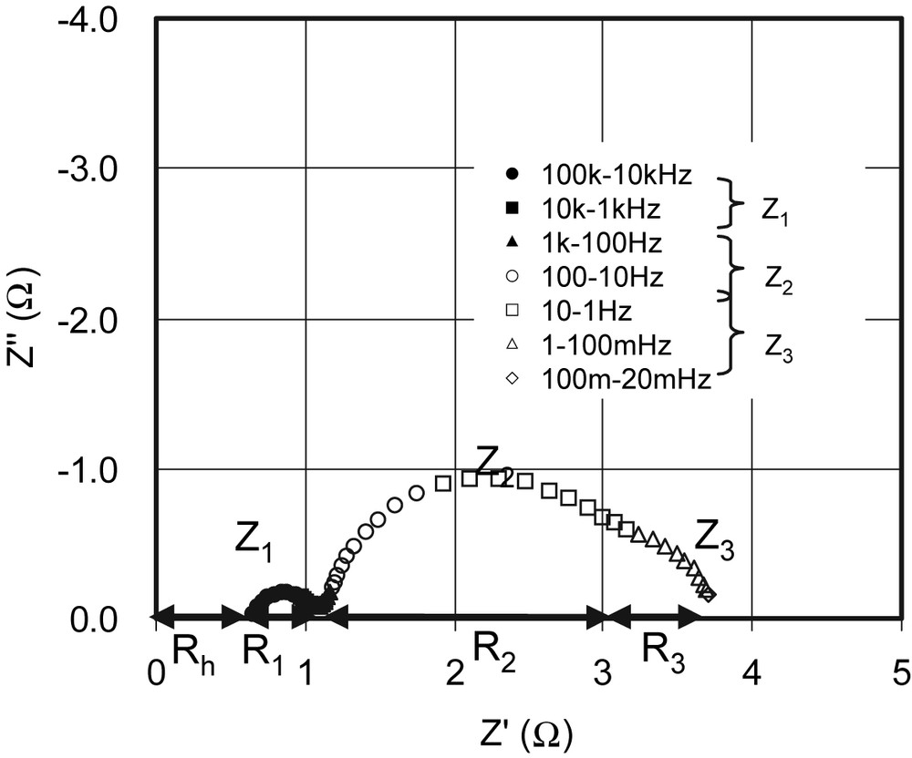
Fig. 1 shows an electrochemical impedance spectrum of a DSC using N3 dye. Three semicircles are observed in the measured frequency range of 20−1 MHz. This suggests there are at least four impedances elements in the DSCs. We define these impedances between 100 and 1 kHz as Z1, 1 kHz to 1 Hz as Z2, 1 Hz to 20 mHz as Z3. The internal resistances of R1, R2, and R3 describe the real parts of Z1, Z2 and Z3, respectively. Because impedance over 1 MHz could not be measured due to instrumental limitations, the resistance element in this frequency region is defined as Rh. The values of R1, R2, R3 and Rh are 0.9, 2.0, 0.6 and 0.8 Ω, respectively. The total internal resistance is 4.3 Ω.
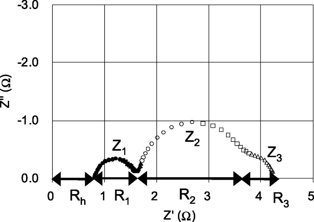
Electrochemical impedance spectrum of a DSC consisting of a TCO∣TiO2–N3 dye∣electrolyte with I–/I3– redox couple∣Pt electrode. Z1, Z2 and Z3 describe as impedances. R1, R2 , R3 and Rh are internal resistance elements. The values of R1, R2 , R3 and Rh are 0.9, 2.0, 0.6 and 0.8 Ω, respectively.
In order to elucidate origins of the semicircles, a variety of different DSCs were constructed by variation of experimental parameters such as the sheet resistance of TCO glass substrate, the roughness factor of platinum counter electrode and cell thickness, and their EIS spectra were studied.
Fig. 2 shows a dependence of Rh on the sheet resistance of TCO glass substrate. It is observed that impedance spectrum is shifted towards higher value of Z′ with increasing the sheet resistance of TCO. The value of Rh is directly proportional to the sheet resistance of TCO. Therefore, it is considered that the resistance element Rh in the high-frequency range > 106 Hz is mainly due to the sheet resistance of TCO.
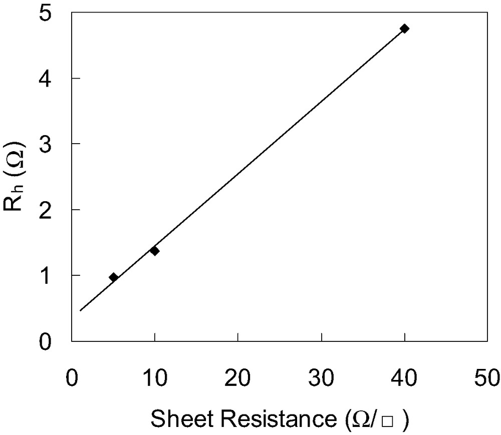
Dependence of Rh of DSCs on the sheet resistance of TCO. Values of Rh are estimated from electrochemical impedance spectra of DSCs consisting of a TCO∣TiO2–N3 dye∣electrolyte with I–/I3– redox couple∣Pt electrode, where sheet resistance of TCO is varied.
Fig. 3 shows the dependence of R1 on the roughness factor of Pt counter electrodes. Pt counter electrodes having different roughness factor were prepared for this measurements. It is found that R1 decreases with increasing the roughness factor of counter electrode. This means that R1 is related to the carrier transport resistance at the surface of Pt counter electrode.
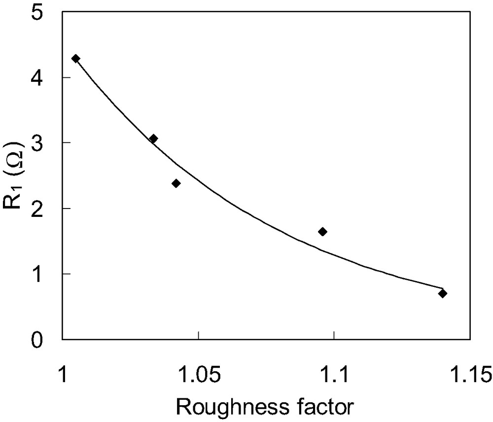
Dependence of R1 of DSCs on the roughness factor of Pt counter electrode. R1 values are estimated from electrochemical impedance spectra of DSCs consisting of TCO∣TiO2–N3 dye∣electrolytes with I–/I3– redox couple∣Pt electrode; using Pt counter electrodes of various roughness factors.
Fig. 4 shows the dependence of R3 on the distance between TCO and Pt counter electrode. In this study, a cell type of Pt/Electrolyte/Pt was used, and spacers with different thickness were used between TCO and Pt counter electrode. It is observed that R3 is proportional to the distance between TCO and Pt counter electrode. Therefore, it is considered that the resistance element R3 is related to the diffusion of iodide and triiodide within the electrolyte.
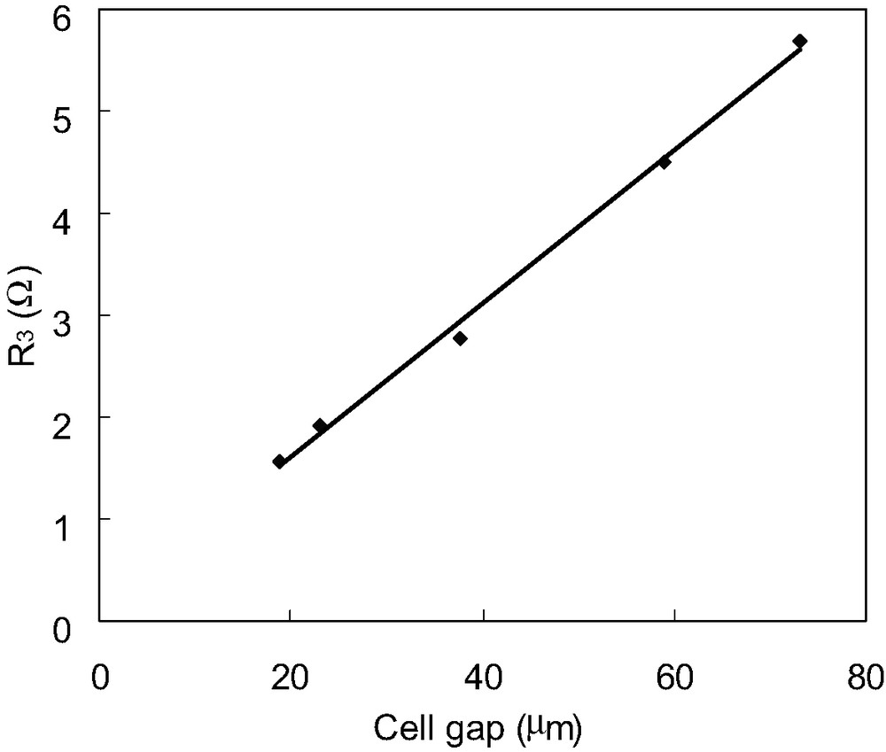
Dependence of R3 of DSCs on the cell thickness. R3 values are estimated from electrochemical impedance spectra of DSCs consisting of Pt electrode∣electrolytes with I–/I3– redox couple∣Pt electrode, where spacers with different thickness were used between the two Pt electrodes to change the cell gap.
On the other hand, the semicircle Z2 is not appeared in the EIS spectrum of the Pt/electrolyte/Pt cell which does not include TiO2 and dye. Therefore, the semicircle Z2 is assigned to carrier transport resistance in TiO2/dye/electrodes interface. Based on the above experimental results, the semicircles Z1, Z2 and Z3 are attributed to impedance related to charge-transfer processes occurring at the Pt counter electrode (Z1), at the TiO2/dye/electrolyte interface (Z2), and to iodide and triiodide diffusion within the electrolyte (Z3), respectively. Among them, the origins of Z1 and Z3 are similar to those reported by Kern et al. [7]. The capacitance elements of Z1 (defined as C1) and Z2 (defined as C2) are estimated to be 2–4 mF and 0.3–70 mF, respectively. The resistance elements of Rh, R1, R2 and R3 are estimated to be several ohms, as shown in Fig. 1.
In general, a solar cell must have a diode-like element, otherwise the power output could not be obtained. However, it is difficult to determine which impedance element shows diode-like characteristics upon EIS measurements under Voc conditions. The ideal current–voltage (I–V) characteristics of a diode are given by
| (1) |
| (2) |
Therefore, the dependences of Rh, R1, R2 and R3 on the applied bias voltage at around Voc were investigated. It is found that only R2 is changed with the applied bias voltage, as shown in Fig. 5, while the others are almost unchanged with the applied bias voltage. The dependence of 1/R2 on the applied bias voltage is also shown in inset of Fig. 5. 1/R2 increases directly proportional to the applied bias voltage, which is consistent with Eq. (2). This result suggests that R2 shows the resistance of the diode element in the DSCs, and is different from that reported by Kern et al., who describe Z2 as reflecting the properties of the photoinjected electrons within the TiO2 [7].
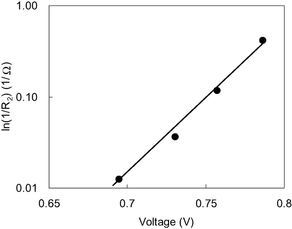
Relationship between R2 and the applied bias voltage. Dependence of resistances 1/R2 on the applied bias voltage. Measurement was carried out under Voc by varying illumination conditions.
Curves (A) and (B) in Fig. 6a show the I–V characteristics of a DSC under conditions of darkness and illumination, respectively. Under illumination, the prepared DSC shows a short circuit photocurrent density (Jsc) of 13.6 mA/cm2, open circuit voltage (Voc) of 0.76 V, and a fill factor (FF) of 0.73 yielding conversion efficiency of 7.5%. Curve (C) is calculated by adding Jsc to curve (A). Curve (C) will expect to equate to curve (B) in case of no series resistance (defined as Rs) being present in the DSC under illumination. However, curve (C) does not coincide with curve (B) as shown in Fig. 6a. Taking into account Rs of 2.5 Ω, which is measured from I–V curve and roughly corresponds to the sum of Rh, R1 and R3 from Fig. 1, the observed shift of curve (C) toward curve (D) can be explained as shown in Fig. 6b. Therefore, Rh, R1 and R3 can be considered to be the series resistance.
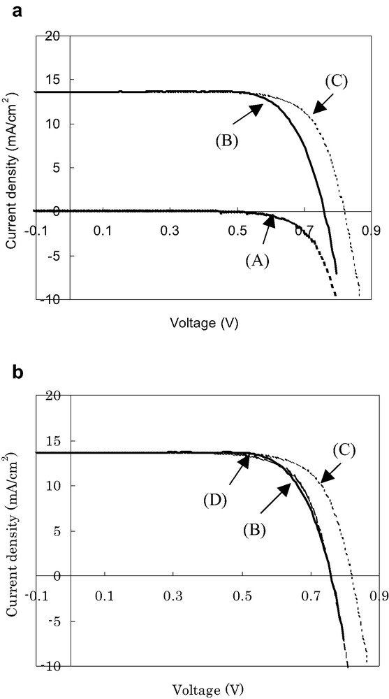
Current–voltage characteristics of a DSC: curves (A) and (B) are measured under conditions of darkness and illumination, respectively; curve (C) is estimated by the sum of curve (A) and Jsc; curve (D) is calculated by subtracting the voltage drop elements from curve (C). Conversion efficiency (curve (B)) under AM 1.5 is 7.5% (Jsc = 13.6 mA/cm2, Voc = 0.76 V and FF = 0.73).
As discussed above, the four impedance elements observed by EIS measurement can be classified as the impedance Z2, which displays a diode-like behavior, and the series impedance of Rh, Z1 and Z3. Therefore, we have proposed an equivalent circuit of DSC as shown in Fig. 7a. Furthermore, a shunt resistance (Rsh), which describes the recombination of the electron from TiO2 electrode to electrolyte, should be added to the equivalent circuit. Rsh cannot estimated from EIS because it is included in R2. However, it can be estimated to be 2 kΩ/cm2 from the I–V curve in Fig. 6. The high value of Rsh indicates a slow back electron transfer rate from TiO2 to electrolytes in the TiO2/dye/electrolyte interface. A constant-current source in which electrons are generated by illumination is in parallel with Rsh. On the other hand, as solar cells generally operate under direct current conditions, the capacitances can be ignored. The series resistance Rs can then be described as
| (3) |
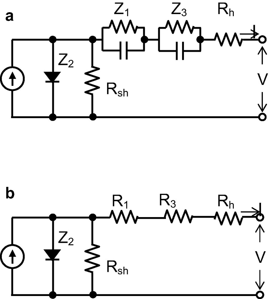
Equivalent circuits obtained from EIS and I–V characteristics of DSCs. Z1, Z2, Z3 are the impedances in DSCs. Z2 is the impedance of a diode. The sum of R1, R3 and Rh largely corresponds to the series resistance of DSCs. A constant-current source is in parallel with Rsh.
The equivalent circuit of DSCs as shown in Fig. 7b can thus be proposed, which is similar to that of a conventional solar cell. This suggests an abundance of experience obtained through the development of high-efficiency conventional solar cells [15,16] can be applied to DSCs.
In order to increase efficiency of DSCs, the internal resistance should be reduced. As mentioned before, the resistance element R1 decreases with increasing the roughness factor of the counter electrode. It is observed that both Jsc and FF are improved with increasing the roughness factor of counter electrode. To reduce the resistance elements, we have optimized the roughness factor of Pt counter electrode, cell thickness, electrolyte composition and dye uptake conditions of the DSCs. A double-layered TiO2 film contained of about 15-nm-sized TiO2 particles and a light scattering layer of about 15-nm-sized and 300-nm-sized TiO2 particles was also developed to increase the light absorption in the longer wavelength region.
Based on the above information, an efficient DSC is fabricated using N719 dye (Fig. 8), which shows a short circuit photocurrent density of 18.2 mA/cm2, an open-circuit voltage of 0.73 V, a fill factor of 0.73 and an overall conversion efficiency of 9.7% under AM 1.5 irradiation (100 mW/cm2).
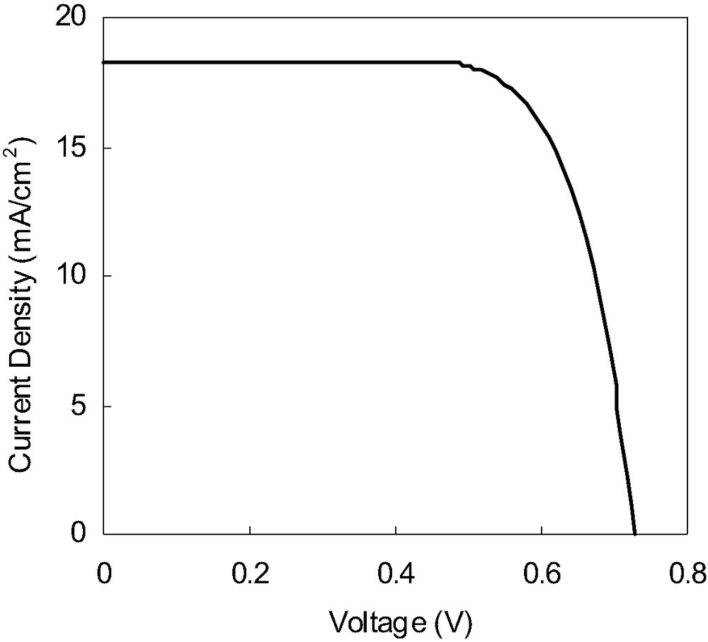
Photocurrent–voltage characteristics of a DSC sensitized with N719 dye. Conversion efficiency under AM 1.5 is 9.7% (Jsc = 18.22 mA/cm2, Voc = 0.73 V, and FF = 0.73). Electrolyte: 0.6 M 1-methyl-3-propyl imidazolium iodide (MPII), 0.1 M LiI, 0.03 M I2, 0.5 M tert-butylpyridine in acetonitrile; TiO2 film thickness: 30 μm. Cell area: 0.25 cm2.
The spectral response in the red and near-IR regions is higher in black dye than red dye, resulting in higher short circuit photocurrent. We have also constructed a nanocrystalline TiO2 photoelectrochemical cell sensitized with the black dye and antireflective coating. The current–voltage characteristics of this solar cell are shown in Fig. 9. A short circuit photocurrent density of 20.1 mA/cm2, an open-circuit voltage of 0.71 V, a fill factor of 0.71 and an overall conversion efficiency of 10.1% is obtained using a metal mask under standard AM 1.5 sunlight.
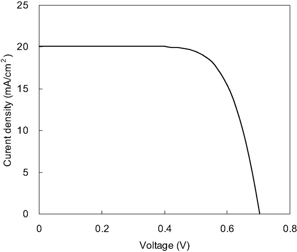
Photocurrent–voltage characteristics of a DSC sensitized with black dye. The results were obtained at 25 °C with an area of 0.2317 cm2 under standard AM 1.5 sun light using a metal mask and antireflective coating. Scan mode from Jsc to Voc. Jsc = 20.1 mA/cm2, Voc = 0.71 V, and FF = 0.71 and the conversion efficiency = 10.1%. Electrolyte: 0.6 M 1-methyl-3-propyl imidazolium iodide (MPII), 0.1 M LiI, 0.03 M I2, 0.3 M tert-butylpyridine in acetonitrile; TiO2 film thickness: 30 μm.
Fig. 10 shows the electrochemical impedance spectrum of this efficient cell. It is found that the impedance spectrum consisted of three semicircles similar to the impedance spectrum shown in Fig. 1. This cell has R1 of 0.4 Ω, R3 of 0.7 Ω, and Rh of 0.7 Ω. The total series resistance of the cell was 1.8 Ω, which suggests that the internal resistance value was much improved after optimization of the cell efficiency (Fig. 10). Especially, the shrinkage of the semicircle (Z1) in the frequency regions 103–105 Hz is significant. This suggests that the observed high performance in DSCs sensitized with black dye is attributed to not only due to enhancement of spectral response in the red and near-IR regions but also due to decrease of internal cell resistance.
Electrochemical impedance spectrum of a DSC consisting of TCO∣TiO2–black dye∣electrolytes with I–/I3– redox couple∣Pt electrode.
The three semicircular shapes are assigned to impedances related to charge transport at the Pt counter electrode (Z1) in the high-frequency region, at the TiO2/dye/electrolyte interface (Z2) in the middle-frequency region, and to ionic diffusion within the electrolyte (Z3) in the low-frequency region, respectively. R1, R2 and R3 are described as the real parts of Z1, Z2 and Z3, respectively. Rh is defined as a resistance in the high-frequency range over 106 Hz. Masquer
The three semicircular shapes are assigned to impedances related to charge transport at the Pt counter electrode (Z1) in the high-frequency region, at the TiO2/dye/electrolyte interface (Z2) in the middle-frequency region, and to ionic diffusion within the electrolyte ... Lire la suite
4 Conclusions
Four resistance elements were observed in the electrochemical impedance spectra of DSCs. According to the dependence of the internal resistance elements of DSCs on the applied bias voltage, the resistance element (R2) related to charge transport at the TiO2/dye/electrolyte interface is considered equivalent to the resistance of a diode. The sum of the sheet resistance of TCO (Rh), the carrier transport resistance (R1) at the surface of Pt counter electrode and the resistance element (R3) related to the Nernstian diffusion within the electrolyte agrees with the series resistance (Rs) of DSCs. Accordingly, the equivalent electrical circuit proposed is composed of a diode (R2), a series resistance (Rs), a shunt resistance (Rsh) and a constant-current source, similar to that of a conventional solar cell. An efficient DSC sensitized with black dye is measured. A short-circuit photocurrent density of 20.1 mA/cm2, an open-circuit voltage of 0.71 V, a fill factor of 0.71 and an overall conversion efficiency of 10.1% was obtained under standard AM 1.5 sun light. This suggests that it is also important to decrease the internal resistance of DSCs to obtain high efficiency, although enhancement of spectral response range to near-IR regions is important.
Acknowledgements
We acknowledge financial support of this work by the New Energy and Industrial Technology Development Organization (NEDO) in association with the Ministry of Economy, Trade and Industry of Japan.