

1 Introduction
Three decades ago the photocurrent generating and solar energy converting properties of chlorophyll molecules in dye sensitization cells, as biometric or bionic models, were first demonstrated [1,2]. Since then, and especially during the last 10 years, dye sensitization cells have seen a significant development [3–6]. However, the analogy with nature in photosynthetic structures was incomplete in one essential respect: technical cells use electrolytic (wet, polymeric, solid) and solid state electronic conduction to generate the electrical circuit which supplies the photo-generated power. The photosynthetic membrane, however, is composed mostly of glycerol lipids in the form of a bi-layer into which the protein complexes are embedded, which make up the photosynthetic apparatus. Photosynthetic electron transport consists of a series of electron transfer steps, from one electron carrier to another over relatively short distances [7–9]. Most electron carriers are metal ion complexes bound with proteins but a few carriers also consist of aromatic groups. Also a non-protein electron carrier is involved (plastoquinon). There are also electron carriers, which simultaneously act as proton shuttles. The reduced plastoquinon molecule, for example, unbinds from photosystem-II and diffuses into the photosynthetic membrane until it encounters a specific binding site on the cytochrome-bf complex. The cytochrome bf complex removes two electrons from plastoquinon (PQH2) and releases protons into the inner aqueous space. Altogether the transfer of an electron from water to NADP+ (Nicotinamide Adenine Dinucleotide Phosphate) involves about 29 metal ions including iron, magnesium, manganese and copper and approximately 7 non-metallic carriers including quinons, pheophitine, NADPH, thyrosine and flavine. Most of these electron transfer steps occur within the lipid environment of the photosynthetic membrane.
The aim of this contribution was to learn about charge separation and charge transfer in lipid (detergent) based environment. The fluid mosaic model for proteins floating in lipid membranes (Fig. 1) should be modeled with a synthetic detergent into which electron-conducting and ion-conducting particles are suspended.
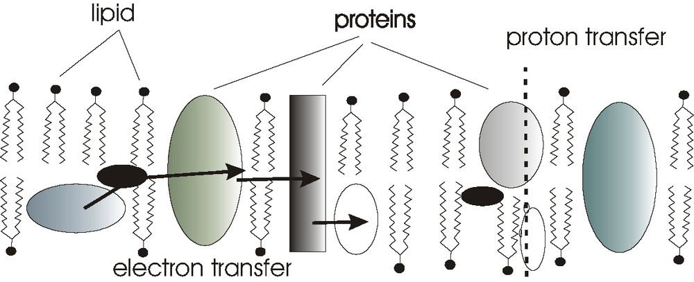
Fluid mosaic model for electron transfer / proton transfer protein chains suspended in lipid environment such as thylacoid membranes.
2 Experimental
2.1 Materials
A mixture of lipid (detergent) with powdered materials and iodine was used to fabricate solar cells. A layer of dyed (cis-Ru(II)(LH2)2(NCS)2) TiO2 was used as absorber. Triton-X was used as a model detergent. It can be replaced by other detergents such as Tween 80. The influence of specific detergent properties on the performance of the cells remains to be explored.
The following are recipes for standard solar cells:
- • Viscous lipid (detergent)-composite paste: On a clean glass plate, 1–2 drops of Triton-X100 were taken and 25 mg of I2 was added and well mixed. 110 mg of powdered ionic conductor was added to this and mixed well to form a uniform suspension. Then 120 mg of conducting carbon glue (containing graphite with acrylic resin in a solvent mixture of xylen, methoxypropylacetate, acetone and butylacetate, as supplied by PROVAC GmbH), was added and mixed well into a paste. Then the paste was transferred to an ITO conducting glass and spread into a uniform layer of 1–1.5 cm2 area. This was pasted on the face of a TiO2-dye-coated (cis-Ru(II)(LH2)2(NCS)2; Ru 535) ITO conducting glass and was held tight using crocodile clips.
- • Viscous iodine binding mixture: because iodine tended to diffuse out from the lipid (detergent) based medium of unsealed solar cells, a complex forming agent was added (ABTS). On a clean glass plate, 1-2 drops of Triton-X100 were taken and 25 mg of I2 was added and mixed well. To this 12 mg of 2,2′-azino-bis(3-ethylbenzothiazoline-6-sulfonic acid) diammonium salt [ABTS] was added and mixed. Then 120 mg of conducting carbon glue was added to this and mixed well into a paste. The whole thing was transferred to an ITO conducting glass and spread into a uniform layer of 1–1.5 cm2 area. This was pasted on the face of a TiO2-dye-coated (Ru 535) ITO conducting glass and was held tight using crocodile clips.
- • Viscous lipid (detergent)-composite mixture with iodine complexing agent: on a clean glass plate, 1-2 drops of Triton-X100 were taken and 25 mg of I2 was added and mixed well. To this mixture 12 mg of 2,2′-azino-bis(3-ethylbenzothiazoline-6-sulfonic acid) diammonium salt [ABTS] was added and mixed. 110 mg of ionic conductor was added to this and mixed well to form a uniform suspension. Then 120 mg of conducting carbon glue was added and mixed well into a paste. The whole thing was transferred to an ITO conducting glass and spread into a uniform layer of 1–1.5 cm2 area. This was pasted on the face of a TiO2-dye-coated (Ru 535) ITO conducting glass and was held tight using crocodile clips.
The performance of such cells is given in Table 1.
Photocurrent and photovoltage output for different composites under 25 mW/cm2 simulated solar light
| Expt. | TiO2-dye | TritonX-100 | I2 | Conducting Carbon | Ionic / Electronic material | V (mv) | Iph (μA) |
| 1 | TiO2-dye | TritonX-100 | - | - | - | 150 | 2.5 |
| 2 | " | " | " | - | - | 380 | 32 |
| 3 | " | " | " | " | - | 400 | 60 |
| 4 | " | " | " | " | Cu2S | 410 | 160 |
| " | " | " | " | " | 430 | 263* | |
| 5 | " | " | " | " | Cu3PS4 | 460 | 157 |
| " | " | " | " | " | 510 | 320* | |
| 6 | " | " | " | " | Cu7PS6 | 500 | 290 |
| " | " | " | " | " | 520 | 760* | |
| 7 | " | " | " | " | Cu7PS6 | 450 | 1500* |
| " | " | " | " | " +ABTS | 390-370 | 270-290** | |
| 8 | " | " | " | " | 0.40 (Cu0,95Ag0,05I) 0.45 (Ag2O) 0.15 B2O3 | 450 | 175 |
| " | " | " | 480 | 390* | |||
| " | " | " | " | " without ABTS | 500 | 1200* | |
| " | " | " | " | " + ABTS | 430 | 280 | |
| 9 | " | " | " | " | 0.40 (Cu0.95 Ag2O.05I) 0.40 (Ag2O) 0.20 V2O5 | 300 | 196 |
| (after 30 min) | 190 | 150 | |||||
| 10 | " | " | " | " | 0.35 (Cu0.95 Ag2O.05I) 0.32.5 (Ag2O) | ||
| 0.32.5 CrO3 | 450 | 283 | |||||
| 11 | " | " | " | " | (after 2 h) | 420 | 198 |
| 0.40 (Cu0.95 Ag2O.05I) 0.30 (Ag2O) 0.30 SeO2 | 510 | 100 | |||||
| (next morning) | 515 | 131 | |||||
| 12 | " | " | " | " | 0.40 (Cu0.80Ag0.2I) 0.45 (Ag2O) 0.15 B2O3 | 400 | 120 |
| (next morning) | 380 | 55 | |||||
| 13 | " | " | " | " | Cu2S–CuCl | 410 | 170 |
| (after 60 min) | 278 | 281 | |||||
2.2 Conducting electrodes
Fluorine-doped tin oxide coated glass plates (FTO) were used. A mixture of 15 ml of Ti[(CH3)2CHO]4 (Aldrich), 17 ml of glacial acidic acid and 30 ml of 2-propanol were hydrolyzed by adding 10 ml of water drop wise under vigorous stirring. 2 g of TiO2 powder (Degussa) were added to the above suspension. TiO2 films were prepared by applying a small amount of this suspension to the preheated FTO glass. It was then thermally treated at 450 °C for 30 minutes. This procedure is repeated to get a considerable thickness of TiO2 on the conducting glass.
2.3 Ion conducting materials
The combined ion conducting, electronic conducting materials we synthesized in the following way.
2.3.1 Preparation of copper phosphor-sulfides
The Cu-ion conductors Cu7PS6 and Cu3PS4 were synthesized from the elements reacting stoichiometric amounts of the elements in evacuated and sealed quartz glass ampoules. In a first step, sulfur reacted with copper with the formation of Cu2S at a temperature of 400 °C within 24 h. In the case of synthesis of Cu3PS4 the ampoule was heated to 600 °C and held for 5 days to obtain a homogeneous yellow material. Cu3PS4 crystallizes in enargite structure, which is related to wurtzite (ZnS) replacing zinc atoms by phosphorous and copper.
To yield Cu7PS6 the ampoule was heated to 950 °C for 2 days. The yellow brownish material belongs to the structural family of the argyrodites [10] and crystallizes in the cubic space group P213.
2.3.2 Preparation of Cu-Ag superionic conductors
The silver ion conductors containing Cu1–xAgxI, Ag2O and the oxides B2O3, V2O5, CrO3 or SeO2 are prepared as follows: Cu1–xAgxI was synthesized [11] by dissolving appropriate amounts of cupric nitrate and silver nitrate in aqueous solution and co-precipitating CuI and AgI from the solution by adding an excess of 5% aqueous KI at normal boiling point. The precipitate after digestion was filtered and washed with water and acetone and dried in the dark at 383 K for 3-4 h. Using this Cu1–xAgxI as the starting material, appropriate amounts of Cu1–xAgxI, Ag2O and metal oxide were mixed well and annealed in a ceramic boat at 893 K for 30 min and rapidly quenched in liquid nitrogen [12,13].
2.4 Interpretation of XRD for B2O3, Cu3 PS4 and Cu7PS6 sample
Fig. 2 (a) and (b) show the XRD spectra of Cu7PS6 and 0.40 (Cu0.95, Ag0.05I) 0.45 (Ag2O) 0.15 B2O3. While the XRD pattern of 0.40 (Cu0.95, Ag0.05I) 0.45 (Ag2O) 0.15 B2O3 shows peaks of small intensity, the patterns of Cu3PS4 (not shown here) and of Cu7PS6 were very well developed. The appearance of less-intense peaks at around 20.3°, 23.5°, 25.9°, 33°, 39.2° and 46.0° in the sample tends to show the presence of AgI (Fig. 2b). CuO was mainly visible at diffraction angles 2 θ = 35.6° and 39.0°: Some weak diffraction peaks corresponding to the presence of metallic silver were noticed around 38°, 44° and 64.6°. This metallic silver present in traces is highly dispersed in the bulk and does insignificantly contribute to the electronic transport [14]. It is also clear that the sample exhibits rather broad and weak absorbance and thus indicates a disordered and glassy-like material.
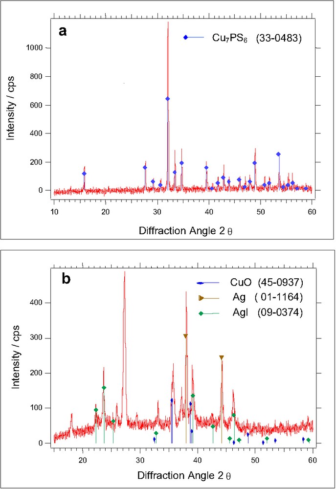
XRD-spectra of (a) Cu3PS7 and (b) 0.40 (Cu0,95Ag0,05I) 0.45 (Ag2O) 0.15 (B2O3).
3 Results and Discussion
Fig. 3 shows a scheme of the cell arrangement used. The two contacting electrodes were CTO-coated glass and TiO2-coated CTO glass. The dye (cis-Ru(II)) 2,2′-bipyridyl-4,4′-dicarboxyl di-thiocyanate, Solaronics) was adsorbed to the TiO2 by shortly boiling a dye containing 2 × 10⁻³ mole solution in ethanol in presence of the TiO2 layer. These different electrodes provide an asymmetric solar cell structure. The gap between these electrodes is now not filled with liquid, polymeric, gel-type or solid electrolyte like in conventional dye sensitization solar cells, but with a dispersion of particles in synthetic detergent environment. When the non-ionic model detergent Triton-X-100 is introduced between the asymmetric electrodes, a negligible photocurrent is flowing. When iodine is dissolved in the detergent, a current of the order of magnitude of 60 μA/cm2 will appear. But this current will rapidly deteriorate as well as the photopotential observed. When chemically modified carbon particles (conducting carbon) are added into the suspension, both the photocurrent and the photovoltage will increase but again, the photocurrent and the photovoltage will not be reasonably stable. When a powder of mixed ionic/electronic material is additionally added, a remarkably high photocurrent and photopotential will develop as shown below. The gap between the asymmetrical electrodes is, therefore, filled with a dispersion of small electronically conducting (carbon) and mixed ionically / electrochemically conducting materials (e.g., Cu7PS6, Cu3PS4, 0.40 (Cu0,95Ag0,05I) 0.45 (Ag2O) 0.15 (B2O3). The iodine dissolved in the detergent may serve as a kind of shuttle. An addition of iodide as it is needed in liquid or polymeric dye sensitization cells has, in contrast, not a positive effect on the function of the solar cell so that the mechanism of charge transfer in lipid (detergent) based environments is still an open question.
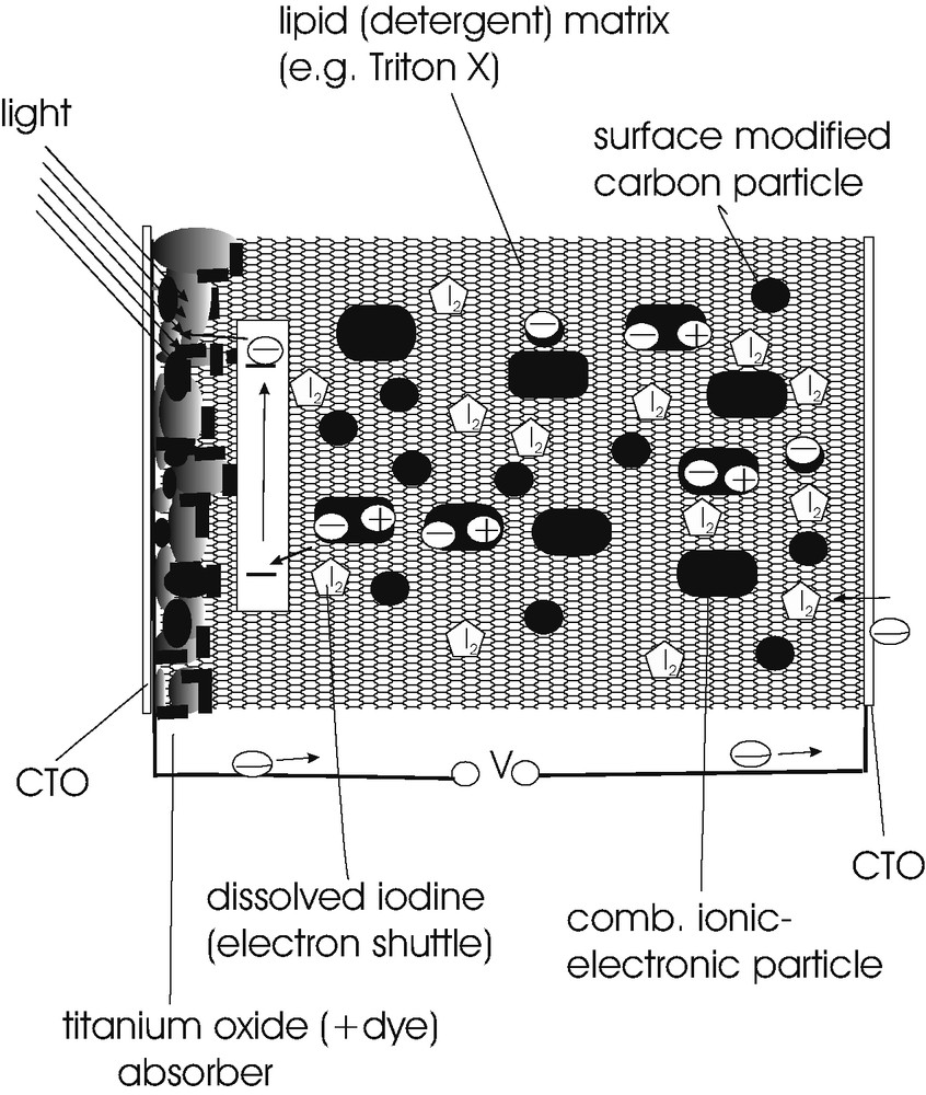
Scheme of lipid (detergent) based composite solar cell. It is shown how a particle suspension in lipid sustains the charge transfer between light absorber and counter contact.
Fig. 4 shows photocurrent intensity plots for different composites in detergent environment. Photocurrent densities of up to 1.5 mA/cm2 under 100 mW/cm2 solar illumination were observed with Cu7PS6 as added combined electronically/ionically conducting particles. It is seen that the photocurrent density-light intensity curves are reasonably linear with a slight saturation towards 100 mW/cm2 light intensity. Fig. 5 shows a light intensity dependence of the photopotential for different composite mixtures. A logarithmic dependence is found for the superion conductor, 0.40 (Cu0.95, Ag0.05I) 0.45Ag2O 0.15B2O3 but a more complicated behavior for Cu7PS6. Fig. 6 shows the current voltage dependence in the dark and during illumination for one of the best performing cells. It reached a short circuit photocurrent of 1.5 mA/cm2, an open circuit voltage of 421 mV and a fill factor of 0.34. The overall efficiency for solar light (100 mW/cm2) was 0.22%. The studied cells were not sealed, the conducting electrodes were simply slightly pressed together and fixed with crocodile clips. Because the solar cells were open, iodine could still escape. This explains a gradual decrease of photocurrent efficiency with time (Fig. 7 a). When iodine was complexed to a suitable organic molecule such 2,2′-azino-bis(3-ethylbenzothiazoline-6-sufonic acid) diammonium salt (ABTS), the photocurrent did not decrease anymore in experiments lasting several days (Fig. 7 b).

Photocurrent–light intensity dependences for different Triton-X-100 detergent based photovoltaic cells. Only the different ion/electronic particle component is indicated. The remaining constituents are identical.

Photovoltage light intensity dependence for two different composites in Triton-X-100 detergent environment.

Photocurrent density voltage dependences for lipid-detergent-based composite solar cell. The power conversion efficiency (at 100 mW/cm2) is η = 0.22%, with a fill factor of 0.34. The open circuit voltage is U0C = 0.421 V and the short circuit current is ISC = 1.5 mA cm−2.


Dependence of photocurrents on time (a) without ABTS and (b) with addition of ATBS.
A cross-section through a lipid composite solar cell containing Cu7PS6 as combined electron- ion conductor particles and surface modified carbon as electronically conducting particles is shown in Fig. 8. It is seen that the lipid based composite is 20 μm thick and the dyed TiO2 layer approximately 50 μm thick. This already shows a significant potential for the reduction of the internal resistance of this experimental cell type. Both layers could easily be reduced by a factor of 5 without hampering light absorption in the TiO2 layer or disrupting charge transfer through the lipid-composite layer. The preparation techniques will have to be developed accordingly.
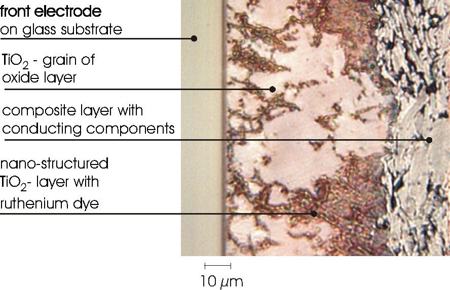
Light-microscopic cross-section of composite lipid solar cell showing the structure of the lipid–composite particle mixture, its contact with the dyed TiO2 layer and the tin oxide contact.
The effect of different composites in Triton-X-detergent are summarized in Table 1. These experiments were, if not indicated otherwise, made under 25 mW/cm2 light intensity. It can be seen that best performance always requires the presence of an ion-conducting/electron conducting component. When silver ion conducting materials were selected, those with little silver and large ion conduction gave the best effect (experiments 8 and 12 in Table 1). When highly pure and finely dispersed carbon (Black Pearls 2000, CABOT, Special Black Sample Nr. GP-3741) was added instead of surface modified conductive carbon, the solar cell completely collapsed. This indicates that the reverse reaction of electrons from TiO2 with the composite dispersed in Triton-X is most important. If the reverse reaction can proceed fast, the power of the solar cell collapses. This explains why chemically modified carbon with acryl resin was needed to obtain a reasonably high solar output efficiency. The surface organic layer on carbon may prevent an efficient reverse reaction of electrons at the interface with sensitized TiO2 particles.
When the lipid (detergent) composite material is sandwiched between the asymmetric CTO and TiO2 dye-CTO contacts, a viscous layer is produced, which is gradually drying because the conducting carbon is loosing its fluidity due to organic solvent loss. In the case of cells fabricated incorporating ABTS after drying almost solid properties are observed.
4 Conclusion
For many experiments with bi-lipid membranes it is known, that electronic charge can only be transmitted in very small currents of the order of nano- to pico-amperes. As our experiments have shown, however, dispersions of electronically and ionically conducting particles in Triton-X-detergent can pass photocurrent densities of more than 1 mA/cm2. Also photovoltages of 0.45 V can be maintained. This first shows that conducting particles in nm-μm dimension dispersed in lipid (detergent) environment can effectively transfer electronic charges and second that the reverse reaction of electrons from the sensitizing dye and from TiO2 is efficiently suppressed. This may also explain the significant role of ion conduction in the composite. An ion conductor is not expected to efficiently react with an electron, but it may allow interfacial electron transfer via ionic reactions, which are maintaining the electron flow through the composite. Since the dispersed particles have sizes in the order of 100 nm to several micrometers an electronic shuttle should be needed. This is apparently the role of dissolved iodine. Iodine may be able to migrate within a micell, which may also be able to trap an electron. Since iodide cannot replace iodine in supporting photocurrent generation, it may be concluded that I– is not soluble directly in the detergent. This subject like many other details still have to be clarified.
The experience gained clearly suggests that charge transfer within bi-lipid environment is a favored process under suitable conditions, which still have to be explored in detail. Electron- or proton-conducting proteins in the photosynthetic membrane will have evolved to guarantee efficient charge transfer. For artificial systems, these conditions will have to be investigated in detail. At present it is not clear how efficient lipid (detergent) based photovoltaic cells will become. But detailed research to determine these limits may be worthwhile in order to explore the possibility of easily producible new composite photovoltaic devices.
Acknowledgements
The authors cordially thank Mr. Peter Schubert-Bischoff for his technical assistance preparing cross section samples of the lipid cell.