

1 Introduction
Nanostructured dye-sensitized solar cells (DSSC) have received significant attention [1–3] and, over the years, much knowledge has been accumulated on various aspects of cell function. They especially include sensitizer function [4,5], electrolyte composition [6–8], charge migration in the nanoporous structure [9,10] and structure [11,12] and composition of the oxide matrix [13,14]. Also theoretical modeling has been undertaken in some detail [15,16]. An analytical formula provided for the function of nanostructured dye sensitization solar cells [17] emphasized the role of electron reverse reaction with the electrolyte at the front contact, together with the reverse reaction of electrons from TiO2 nano-particles for the efficiency of the dye solar cell. This means that both, the surface of TiO2 nano-particles and the F:SnO2 surface of the conducting front contact are critical for the performance of dye sensitization solar cells. In the first case, on the TiO2 nanoparticles, the surface determines the electron injection rate and the reverse reaction of electrons with the oxidized dye and the electrolyte. On the SnO2 front contact, it critically determines the rate of reverse reaction with the electrolyte, which has to be minimized. The experiments of this publication were aimed at testing the relevance of this conclusion by designing appropriate experiments using photocurrent imaging techniques.
2 Experimental
2.1 Materials
Optically transparent conducting glass (F:SnO2, sheet resistance 10 Ω/□, thickness 2 mm) was purchased from Asahi Glas (Japan). TiO2 (P25) came from Degussa and was used as received. Ethanol (absolute, Merck), acetonitrile (p.a., Fluka) and Isopropanol (p.a., Fluka) were used without further purification and stored over 4-Å molsieve. Anhydrous LiI (p.a., Fluka), Triton X (Fluka), I2 (double sublimated, > 99%, Merck) and acetylacetone (p.a., Merck) were also used without special treatment.
2.2 Preparation of the electrodes
Twelve grams of TiO2 (P25) were added to a solution of 62 ml ethanol, 400 μl Triton X and 400 μl acetylacetone. The suspension was treated in an ultrasonic bath for 90 s to homogenize and downsize the average dimension of the TiO2-agglomerates. The front electrode was coated with TiO2 by dipping the FTO-glass into the suspension several times. In each cycle, the electrode was dipped, pulled out and dried at room temperature, so that layer thickness increased by 2 μm in average. These plates were used to make lengthy electrodes (4.5 × 1.5 cm2 most often) by partially removing the TiO2-layer with a cloth. After annealing them at 450 °C for 45 min they were transferred into a 1.25 × 10⁻⁴ M solution of Ru-535 in absolute ethanol at room temperature for 1 day.
The FTO-counter electrode was platinized by dropping 25 μl of a 0.5 mM H2PtCl6-6 H2O solution onto the glass followed by annealing at 380 °C for 15 min. Both electrodes were clamped together with Surlyn® foil which was deposited between the glass plates, heated to 100 °C and pressed for 3 min at 2 kN. The electrolyte (0.5 M LiI, 0.05 M I2, 0.2 M 4-tert-butylpyridine in acetonitrile) was filled between the electrodes with the vacuum method. The interior of the cell was evacuated, put into the electrolyte and exposed to room pressure.
Finally the cell was hermetically sealed with TorrSeal vacuum glue. The solar cell efficiency was in the range of 3–5%, mainly due to the comparatively low TiO2-layer thickness (8 μm).
2.3 Deposition of thin oxide layers
An ultrathin layer of Al2O3 and ZnO was deposited onto TiO2 by chemical bath deposition (CBD).
Precursor solution for Al2O3:
In a glove box 3.84 ml (0.015 mol) Al(iBu)3 were dissolved in 100 ml isopropanol.
Precursor solution for ZnO:
One hundred ten milligrams (0.5 mmol) zincacetate were dissolved in 100 ml H2O.
Precursor solution for PtO2:
Twenty-five microliters of 0.5 mM H2PtCl6-6 H2O, solution was directly sprayed onto the surface.
Precursor solution for RuO2:
2,5 mM solution of RuCl3 in dry 2-propanol.
The TiO2 electrodes were dipped into the respective precursor solution for a few seconds, dried at room temperature and annealed for 20 min at 430 °C. As found by other authors [21], the growth of the overlayer is mainly a function of dipping/annealing cycles and precursor concentration but relatively insensitive to dipping time and temperature. For Al2O3/ZnO, the variation of the layer thickness was achieved by different numbers of dipping cycles and for RuO2/PtO2 by different precursor concentrations.
To obtain a thickness gradient within one cell, lengthy TiO2 electrodes were coated stepwise, so that one end was covered by up to four layers.
2.4 Methods
The thickness of the TiO2 layers was determined by a Dektak-Step-Profiler (Sloan Dektak 3030 – Veeco Instruments). For all cells described below, it was between 8 and 10 μm.
The Scanning Microscope for Semiconductor Devices (SMSC) apparatus was developed at the Hahn–Meitner Institute and consists of red laser (632.8 nm) with a spot diameter between 0.4 and 400 μm. The beam is directed onto the sample that is free to move into two directions. By measuring the photocurrent point by point two dimensional photocurrent images are obtained.
3 Results and discussion
3.1 RuO2 and PtO2 coated electrodes
Since the chemical attachment of the ruthenium sensitizer is critically determining its long-term stability, modifications of the TiO2 surface may provide relevant information towards long term stabilization of dye sensitization solar cells. The combination of photocurrent imaging techniques and combinatorial experiments (partial exposition of the TiO2 layer to different chemicals) within the same solar cell allow the collection of relevant experimental information in spite of a certain variability of dye solar cell quality [18,19].
A most important question concerns the influence of interfacial bonding on the long-term stability of the sensitizer. Space resolved photocurrent measurements in combination with partial illumination of the solar cell surface and an only partial surface modification provides quite reliable information on relative photodegradation within one and the same solar cell.
As Fig. 1 shows, partial treatment of the FTO-glass or the TiO2-layer with RuCl3 solutions of different concentration both yielded a drastic decrease of the photocurrent in the affected areas. No photocurrent could be measured in cells that dipped into a precursor solution of 10 mM RuCl3 or higher. For 5 mM precursor solutions, the photocurrent reached about 10% of the unaffected areas, increased to 25% for a 2.5 mM (Fig. 1) and 50% for a 0.25 mM precursor solution. RuO2 catalyzes the electron backward reaction to the electrolyte and therefore strongly enhances interfacial charge reverse reaction.
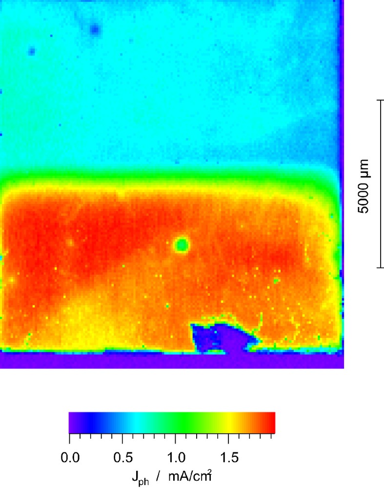
Photocurrent image of a cell that was partly treated with 2.5 mM RuCl3 solution (upper, blue part).
I3– + 2e– → 3 I–
The photocurrent Jph is inversely proportional to the recombination rate k4 [17] and, since all other cell parameters are kept constant in this experiment, one has a direct correlation between the two variables.
| (1) |
The photocurrent image also reveals that there is neither a considerable electron transfer directly from the F:SnO2 to the electrolyte nor a transfer from the F:SnO2 back to the conduction band of the TiO2. That means that F:SnO2 rather behaves like a highly doped n-type semiconductor than a conventional metal and the TiO2/F:SnO2 is a rectifying and not ohmic contact. To raise an additional argument: if it were purely metallic, the electrons could move freely and a uniform photocurrent would be expected over the whole area.
A clear decrease of photocurrent efficiency could also be obtained by treatment of the FTO-glass with 25 μl of 0.5 mM H2PTCl6-6 H2O solution. In average the photocurrent decreased by 50% in the coated areas. This simulates the situation normally encountered at the counter electrode where the electrolyte is regenerated. Again the unaffected parts still function properly although the electrons transferred from the TiO2 to the F:SnO2 layer could easily engage in a reverse reaction in the coated area without traveling through the outer electric circle if the F:SnO2 layer was metallic.
3.2 Degradation and photocurrent of ZnO-coated dye-sensitized solar cells (DSSC)
One of the most important limitations of DSSC efficiency is the reverse electron transfer from injected electrons of the TiO2 semiconductor to the redox electrolyte or the oxidized dye molecule, the first being particular critical for the device function. Recombination reaction to the I3– can either occur with electrons from the TiO2 conduction band or with electrons from surface or trap states. In the last few years, a concept based on a core/shell configuration was introduced [20–28] that is aimed to install an energy barrier between the semiconductor matrix and the electrolyte. These electrodes consist of core of an inorganic semiconductor (most commonly TiO2, SnO2 and ZnO less often) which is covered with a thin (up to a few nanometers) shell of another metal oxide. Preferably the conduction band of the metal oxide should have a more negative potential than the core semiconductor in order to establish an energy barrier for the electrons. Though at a first glance both electron injection and recombination reaction should be affected to the same extend, transient absorption data for Al2O3-coated TiO2 showed [28] that the injection rate is affected negligibly, whereas reverse reaction rates are decreased considerably for ultrathin Al2O3 layers. This is theoretically still not fully understood but it is believed that coverage of the surface trap states might be the reason for the one-sided slowdown.
So far thin layers of ZnO [20,27], Al2O3 [20,28], Nb2O5 [22] and SrTiO3 [23] on TiO2 nanoparticles were found to increase the cell efficiency whereas SnO2 [20], ZrO2 [20,21] and SiO2 [21] layers on TiO2 turned out to have a negative effect on cell efficiency. Experiments performed with nanoporous SnO2 particles revealed an increase in cell performance if the electrode is coated with MgO [24] or TiO2 [25]. It should be noted, however, that the stated improvement of cell parameters between 15% and 35% come from comparisons with uncoated cells which had efficiencies that did not exceed 8%. It is still not known if these results are transferable to cells with higher efficiencies [26].
Other open questions include the thickness, morphology and surface coverage of the shell-layers, the latter especially important for the binding of the dye to the semiconductor and its impacts on long-term stability. Another key problem is the low reproducibility of DSSCs, as its performance is extremely sensitive to slight deviations in the manufacturing process so that many cells have to be compared before one has a statistically significant result [26].
In this paper we employ space resolved photocurrent images of cells that are partially coated with a ZnO and Al2O3 layer of increasing thickness to ensure that all cell parameters except the one of interest are the same. With this technique one can monitor the relative photocurrent change of modified TiO2 layers within one cell, which explicitly reduces the experimental effort to achieve significant experimental data. This setup is also used to monitor the effects of coated TiO2 on long term stability of the cells.
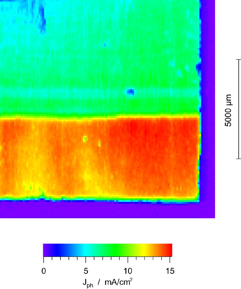
A lengthy TiO2 electrode of 42 × 10 mm was coated with an increasing layer of ZnO by chemical bath deposition. The upper limit for the layer thickness was determined to be 15 nm by scanning tunneling microscopy (STM). The two dimensional photocurrent images were reduced to one dimension by taking the mean photocurrent value along a row for each parallel line. One should note that the measured photocurrent can neither be identified as the macroscopic short-circuit current ISC nor as the photocurrent with an external resistor IPh because the illuminated area is only defined by the laser spot area (50 × 50 μm; the laser intensity was adjusted so as not to exceed solar light intensity AM 1.5). This may significantly affect the regeneration rate of the redox electrolyte as for example the diffusion rate is enhanced considerably due to a radial geometry. We will refer to this current as ISMSC and assume that it is proportional to the photocurrent IPh.
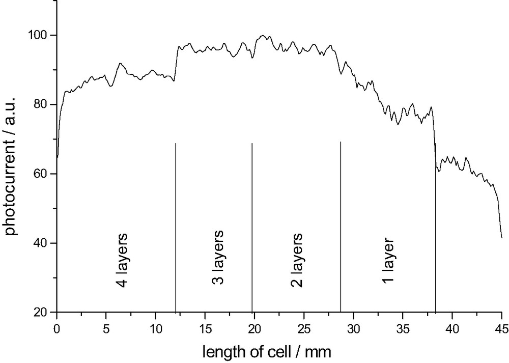
Fig. 3 and 4 show that the photocurrent ISMSC decreases by 20% for parts that have been dipped once, increases linearly for two to five dipping cycles and reaches a plateau for six dipping cycles. We can not conclusively account for the decrease after one dipping cycle but it might be reasonable to assume that the overcoat is too thin to shield surface trap states. Obviously one layer modifies the surface properties in an unwanted way since this result was repeatedly found in five consecutive experiments. With increasing overcoat thickness surface trap states are more effectively shielded and thus the recombination rate decreases. It is important to see that in contrast to wide bandgap semiconductors like Al2O3, the ZnO layer is not an energy barrier as it has similar conduction- and valence band positions. Therefore the photocurrent ISMSC graph reaches a plateau and not a maximum when the overcoat thickness is further increased.
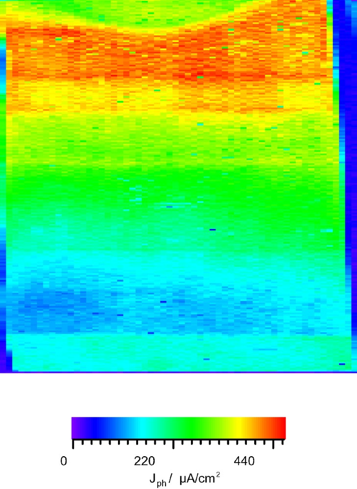
Photocurrent image of a dye sensitization cell stepwise coated with ZnO of increasing layer thickness from bottom to top.
Remarkably the degradation rate of the DSSC is as well a function of the overcoat thickness. As shown in Fig. 4b it increases linearly with the layer thickness. One would have expected a direct proportional relationship between the initial photocurrent and the degradation rate but it turned out that it is above average so that the photocurrent graph after 2 weeks of illumination passes through a maximum. Parts with thick ZnO layers do not reach the photocurrent density of uncoated parts anymore. The degradation process can be divided into light-induced and a light-independent processes. Fig. 5 points out that degradation in darkness is in average around 15% slower but reaches almost the rate of illuminated parts for a thick ZnO overcoat. Light induced processes include photochemical degradation that consists of ligand exchange, oxidation and other decomposition reactions which are discussed elsewhere [29,30]. They are not related to the metal oxide coating and take place in every DSSC. Another critical process is the regeneration of oxidized dye-molecules by the redox electrolyte. Since the dye molecule in the oxidized state is especially susceptible to degradation reaction an unhindered diffusion of the I– ions is essential to ensure a fast regeneration. The deposited ZnO layer narrows the TiO2 pores so that they might be more difficult to access for the iodine ions which might lead to a faster degradation.
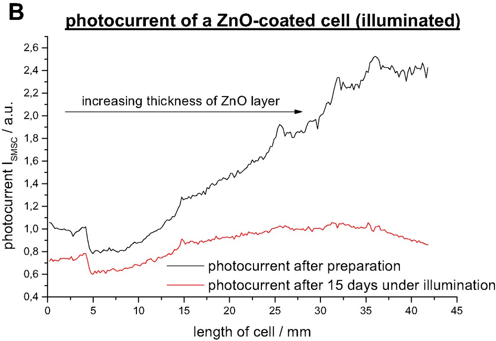
Photocurrent ISMSC after preparation and after 15 days under illumination AM 1.5.
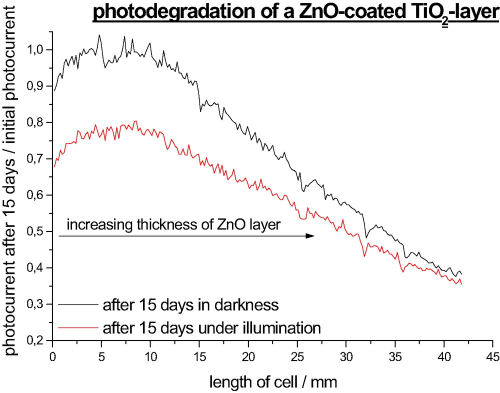
Decrease of photocurrent ISMSC after 15 days under illumination AM 1.5 and in darkness.
Yet the dominant degradation pathway is light-independent (Figs. 4a and 5). Though several processes have been identified which enhance cell degradation in the darkness (imperfect sealing, water penetration, electrolyte decomposition) only little is known about the relevance of each of them. The binding between the dye molecule and the semiconductor seems to be critical for stability of the device. Obviously the degradation rate is faster if the dye is attached to ZnO than to TiO2. A possible explanation might be an enhanced saponification rate of the ester linkage in the TiO2/ZnO system.
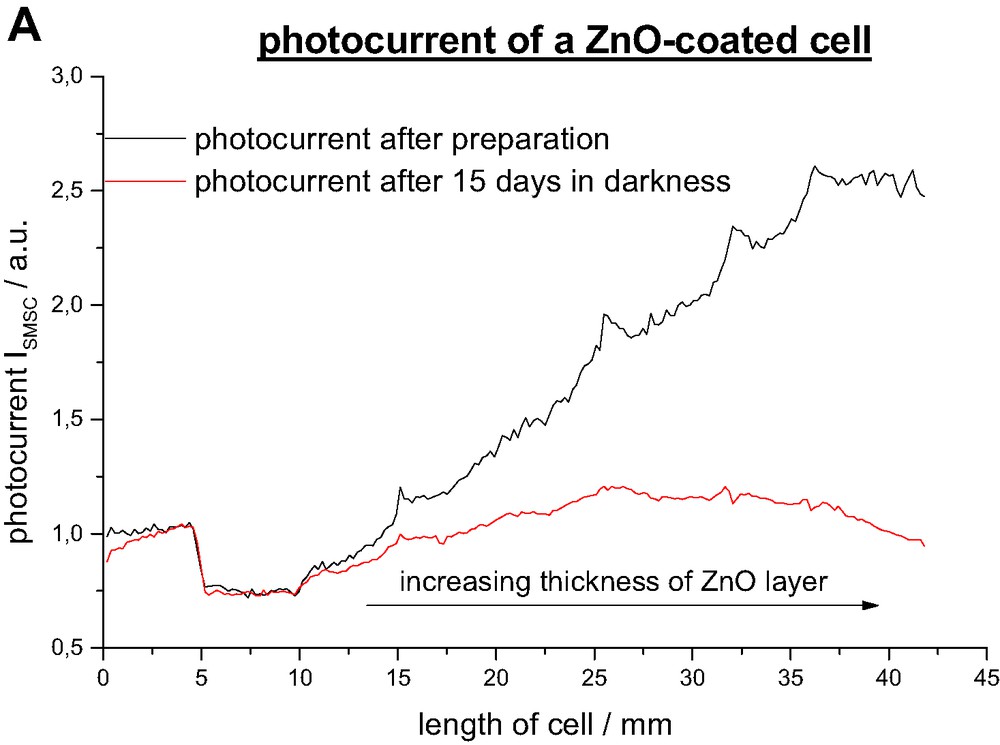
Photocurrent ISMSC after preparation and after 15 days in darkness.
3.3 Photocurrent of Al2O3-coated DSSCs
Al2O3 is an insulator with a bandgap of ca. 8.5 eV (ECB = –4,5 eV, EVB = +3,85 eV vs. SCE). An ultrathin layer coated on nanoporous TiO2 electrodes acts as an energy barrier that retards the recombination reaction significantly whereas charge injection remains unaffected up to a certain layer thickness [28]. It should be noted that the coating of TiO2 particles with aluminum oxide is usually realized by annealing an aluminum precursor solution at temperatures between 400 and 450 °C under an oxygen atmosphere, which makes a complete dehydration rather unlikely and the chemical formula of the deposited layer is of the form AlxOy·OHz. Yet, since the precise composition is difficult to assess, we will refer to the oxide as Al2O3 as usually done in the literature.
An interesting property of Al2O3 is its low isoelectric point of pZC = 8–9, which makes it a very basic oxide. So one reason for the enhanced cell performance might be simply that Al2O3 is more electrophilic and the attack of the carboxylic group of the Ru-complex is easier. Therefore the esterification is enhanced and the dye concentration on the surface is higher than in non-coated parts of the cell (one should note however that conditions in an ethanol solution might differ from water). Fig. 6 shows the photocurrent ISMSC vs. the thickness of the TiO2 layer. Two dipping cycles are optimal for the functioning of the cell resulting in an increase of ISMSC of 40%. Thicker Al2O3 are not favorable because the energy barrier becomes too extended so that electrons cannot be injected into the conduction band of the TiO2 anymore.
Photocurrent vs. thickness of Al2O3 overcoat.
4 Conclusion
Deposition of ultrathin layer of Al2O3 and ZnO on TiO2 improves the property of electron transport in nanoporous TiO2 films, resulting in a significant increase in short-circuit photocurrent and overall power conversion efficiency. The enhancement is mainly due to a slowdown of the reverse reaction. The deposited metal oxide layer covers surface trap states on the TiO2 nanoparticles and thus reduces the concentration of trap sites. Long-term stability tests revealed that cells coated with ZnO are more susceptible to degradation even if not illuminated. It is concluded that the binding between the dye and the semiconductor is less stable. As discussed in [17], the efficiency of dye sensitized solar cells should be most critically determined by two kinetic reaction constants. These are the rate of reverse reaction (k4) of electrons from TiO2 particles with the I–/I3– redox electrolyte, and the reverse reaction rate of electrons (sr) from the FTO front contact with the I–/I3– redox electrolyte. This contribution was aimed at testing this model by modifying both reaction constants. Acceleration of rate constant sr at the front contact by applying a catalyst (Pt, RuO2) layer indeed verified a breakdown of cell efficiency (Figs. 1 and 2). Applying a thin sur-layer of ZnO and Al2O3 onto TiO2 nanoparticles, which reduces the reverse reaction of electrons with the electrolyte (reduction of k4), also showed the expected result in increasing the photocurrent efficiency (Fig. 3, 4 and Fig. 6). However, at the same time it became apparent, that degradation of the cell performance, both in the dark and under illumination is getting more pronounced.
Photocurrent image of a cell that was partly coated with 0.5 M H2PtCl6·6H2O solution, so that Pt particles form (upper, green part).
This means that the bonding of the Ru–N3 dye to the oxide is most critical for stability and that the conditions are less favorable when the Ru–N3 complex is bounded to ZnO, compared to TiO2. Even for TiO2, a strong chemisorption and bonding of the Ru-complex appears to be necessary for high photostability, since weak adsorption and unfavorable adsorption sites lead to strong dye photodegradation.
This shows that there is a relation between the photostability of the oxidized Ru-complex and the chemical bonding of the complex to the oxide. Why there is such as significant influence of interfacial chemical bonding on stability will have to be subject of further studies.