

1 Introduction
In aqueous media, electrochemical methods can be used to control the growth, on InP, of different kinds of oxide structures [1–5]. In particular, at pH 9, the growth and formation of thin InPO4-like anodic films have been evidenced [6–8]. By modifying the anodization parameters (i.e. current density and treatment time), the oxide coverage can be controlled from an island stage up to a complete covering by a homogeneous layer with good electrical blocking properties [6–8].
Anodic treatment can be carried out in true water-free conditions when using high-purity (electronic grade quality) liquid ammonia (NH3 liq.). As a polar solvent, NH3 liq. exhibits unique physical properties such as low viscosity, allowing better conductivity than in aqueous media. Compared to water its low dielectric constant makes liquid ammonia a poorly dissociating solvent. Ammonia molecules are therefore available for chemical interfacial processes onto semiconductors. Thus, a new interface is expected due to oxygen-free surfaces and an interfacial electrochemistry ruled by ammonia molecules. A reproducible thin passivated film involving phosphazene terminations has recently been evidenced by XPS analyses and stability tests. A specific “P–N” surface chemistry was evidenced and associated with a phosphinimidic amide-like electrodeposition [9,10]. The efficiency of this new passivation route was supported by the high stability of the complete covering thin film, since no air ageing effect is detected on the InP surface [9,10].
The aim of this present work was, on the one hand, to investigate in liquid ammonia the chemical stability of anodic oxides prepared in aqueous media and, the other hand, to combine the good electrical blocking properties of this oxide layer with specific “P–N” surface bonds resulting from anodic treatment in liquid ammonia.
2 Experimental
n-InP wafers with a (100) orientation were purchased from InPact Electronic Materials, Ltd, with a doping density of 1018 cm−3. The wafers were cut into small squares (0.5 × 0.5 cm2). Prior to use, semiconductors were chemomechanically polished with a solution of bromine in methanol (2%), and rinsed with purest methanol and dried under an argon stream [4,8,11–13]. In order to remove residual oxides, samples were dipped for a few minutes in 2 M HCl just before the experiment [8,14,15].
The electrochemical set-up was a classical three-electrode device, using a 283 EG&G potentiostat–galvanostat. Anodic treatments were initially done in an aqueous borate buffered Tritisol (Merck) solution, at pH 9, using a classical three-electrode configuration with a Mercury Sulfate Electrode (EMSE = +0.65 V/SHE) as reference and a large Pt counterelectrode. Oxidation treatments in aqueous media were carried out by applying a constant anodic current density, Ja = 0.2 mA cm−2. Treatment durations varying from 1 s to a few minutes were applied. Capacitance measurements vs. potential, C(V), were used to probe the oxide covering level. C(V) measurements were carried out in the dark, before and after oxidation treatments, in aqueous media, with a linear potential scan of 10 mV/s. The sinusoidal modulation frequency was set at 1107 Hz and the peak-to-peak amplitude at 20 mV.
Ammonia condensation, from gaseous ammonia (“electronic grade” from Air Liquide), was provided by a glass column assembly and required a low operating temperature under atmospheric pressure [16]. An electrochemical cell filed up with 150 cm3 of liquid ammonia was maintained at 223 K in a cryostat. The acidic medium was obtained by addition of 0.1 M NH4Br (purest available quality from Aldrich). All potentials were measured vs. a silver reference electrode (SRE) [17]. The electrochemical set-up was also a classical three-electrode device, with a linear potential scan of 20 mV/s. Current–voltage curves were performed under illumination using an optical fiber with a tungsten lamp. After the anodic treatment in NH3 liq. at open circuit, InP was rinsed in purest liquid ammonia and the sample was then transferred towards an XPS analyzer using a procedure avoiding any air contamination [10].
XPS analysis was performed on a V.G-Escalab 220 iXL, spectrometer. A focused monochromated X-ray beam (Al Kα) was used for excitation. For detection a constant analyzer energy mode was used, with pass energy of 8 or 20 eV. Photoelectrons were collected perpendicularly to the surface. Calibration of the spectrometer was done using the E902-94 ASTM procedure. Fitting procedures were performed with the Thermo VG ECLIPSE program.
3 Results and discussion
3.1 Anodic oxide growth in aqueous medium
n-InP anodic treatment was carried out at pH 9 with a current density of 0.2 mA cm−2 for durations, tox, ranging from 1 s to a few minutes. Mott–Schottky representations, C−2(V), recorded in the dark and corresponding to different modified electrodes, were plotted in Fig. 1B–H and compared to the representation corresponding to the clean surface (Fig. 1A). Two strongly different C−2(V) behaviors were clearly established. For short anodic treatments (tox < 10 s), a parallel shift of C−2(V) lines was observed (see Fig. 1A–D), while for longer ones (tox > 30 s) nearly flat and reproducible curves were recorded (see Fig. 1G and H). Between these two limiting behaviors, an intermediate regime was detected, with a progressive loss of the Mott–Schottky parallel shift. This strong modification of the C(V) response reveals an important evolution of the InP surface occurring during the anodization process. Previous works have shown that Mott–Schottky measurements were very sensitive to the oxide covering level [6,8]. Indeed, for tox ranging from 1 to 10 s, the C−2(V) curves evidence a linear behavior with a progressive positive shift, keeping the constant slope recorded on the clean surface. In these conditions, the presence of oxide islands on the InP surface has been evidenced [8]. Hence, during this initial stage of the process, the surface can be considered as a mixture of covered and uncovered zones, the amount of uncovered zones decreasing while tox increases.
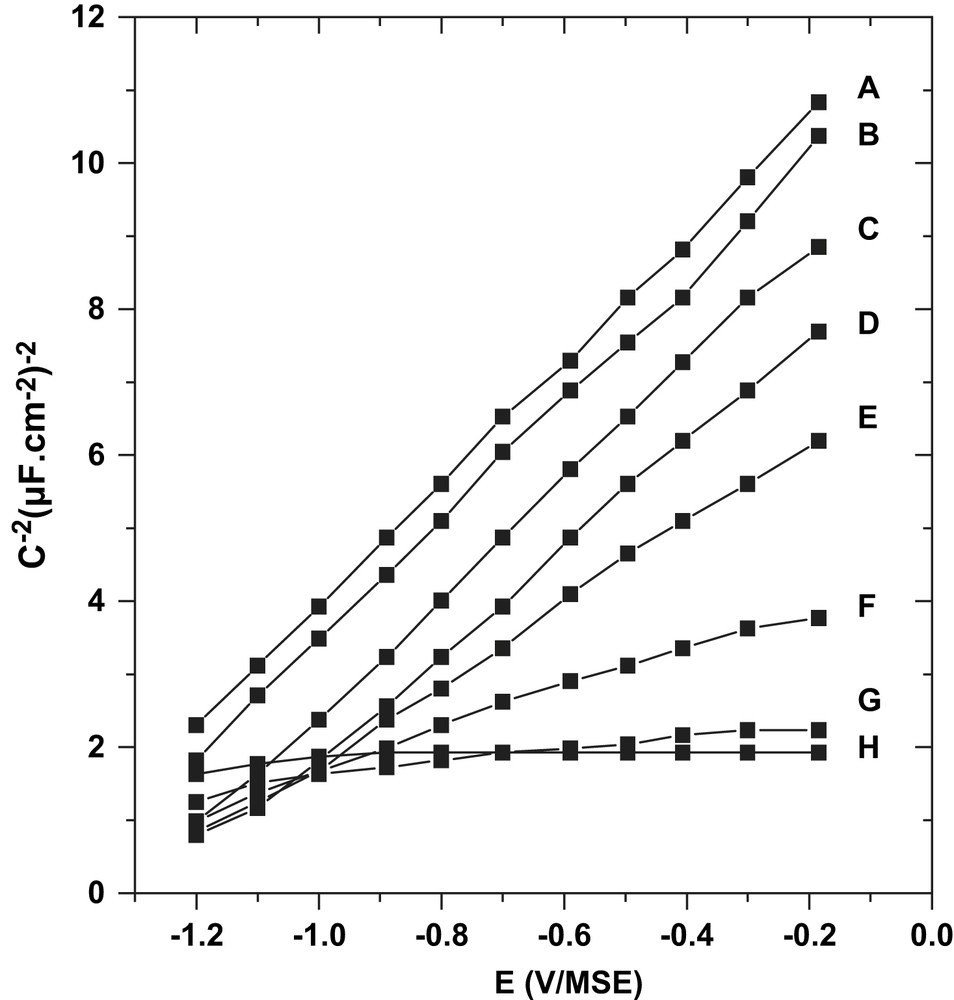
Mott–Schottky plots, in the dark, on n-InP, f = 1107 Hz, pH 9, A: clean surface; B: oxidized 1 s at 0.2 mA cm−2; C: 5 s; D: 10 s; E: 15 s; F: 20 s, G: 30 s; and H: 2 or 15 min.
A final stage of oxide formation occurred for tox > 30 s (Fig. 1G and H). In these conditions, a quasi-constant and very reproducible capacity response was recorded for a wide potential window of 4 V [8]. Depending on the experiment, the value of the C(V) saturated level was set between 0.7 and 0.9 μF cm−2 and maintained when the oxidation treatment was prolonged up to 30 min. XPS analyses corresponding to different anodic durations were reported in Fig. 2. In comparison to the initial clean surface, In3d5/2, In3d3/2 and P2p peaks present new contributions positively shifted in binding energy, evidencing the presence of oxidized phases for which In and P atoms are bounded to O atoms. These new contributions were noted “In–O” and “P–O”. A quantitative exploitation of these spectra has been made in a previous work [8]. Between 5 s to 1 min of anodic treatment, the ratio of the peak areas “In–O”/“P–O” was close to 1, evidencing the presence of an indium phosphate-like phase at the interface. Average oxide thicknesses have also been deduced from XPS results. After a few minutes of anodic treatment, a limited thickness (4–8 nm) of InPO4-like film fully covers the semiconductor.
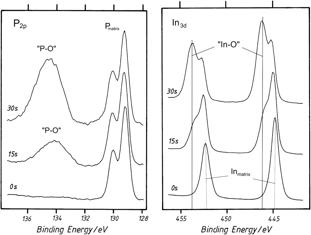
XPS spectra on n-InP (0 s): a clean surface (15 and 30 s): after oxidation in aqueous media (pH 9) at Ja = 0.2 mA cm−2 for 15 and 30 s.
3.2 Anodic treatment in liquid ammonia
Three surfaces of InP (noted A, C and H) have been characterized during exposure to liquid ammonia. The InP surface noted A corresponds to a bare surface. This surface was immerged in NH3 liq. just after a suitable chemical etching of InP, obviously without anodic treatment in aqueous media at pH 9. The InP surface (noted C) is associated with an initial surface covered with oxide islands. Before the anodic process in liquid ammonia, an anodic oxide growth was then previously carried out in aqueous media at pH 9 by a galvanostatic treatment of 5 s. Finally, the third InP surface (noted H) corresponded to a fully recovered surface with a limited oxide layer (3–5 nm). Before recording the current–voltage curves in NH3 liq., a complete recovering of the surface was then previously obtained in aqueous media at pH 9 by a galvanostatic treatment of 5 min.
Current–voltage measurements performed on three different surfaces (A, C and H) in liquid ammonia are shown in Fig. 3. The applied potential was scanned from −0.5 to 1.1 V vs. SRE under illumination conditions. Under illumination on the bare InP surface (noted A), the anodic current gradually increased until +0.5 V, corresponding to the anodic peak (Fig. 3A). This anodic wave was immediately followed by a current increase from +1.3 V without obvious limitation. In a previous work in liquid ammonia, we already have demonstrated, from quantitative analyses of the indium element [18,19], that the unlimited current was caused by InP dissolution according to a six-hole mechanism (Eq. (1)). For the n-type, this current was ascribed to the InP porosification [19]:
| (1) |
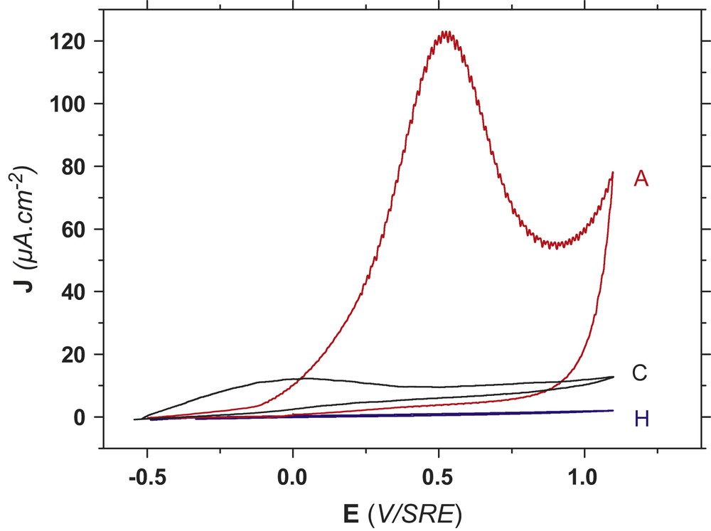
Anodic cyclic voltammetry onto n-InP in acidic NH3 liq., at T = 223 K, NH4Br = 0.1 M under illumination for three different chemical compositions of InP surface. A: Bare InP. C: InP covered with oxide islands. H: InP covered with a homogeneous oxide film.
Anodic charge involved in the anodic peak was close to 5 mC cm−2. In the dark, the anodic peak was located at +1.2 V that is in front of the InP dissolution [9,10]. Under illumination on the n-type, a reduction of the anodic overvoltage by 700 mV was observed since the anodic peak moved back to +0.5 V. As a result, the InP porosification process could be easily avoided under illumination. As soon as the anodic wave has been generated, the anodic behavior of InP was drastically modified during the reverse scan. The anodic wave did not emerge again, only the unlimited current was still observed. This stable passivation phenomenon has already been investigated by XPS [9,10]. From XPS analyses reported in Fig. 4, an increase of the nitrogen component was observed as well as a new phosphorus contribution at 133 eV. The increase of the oxidation state of phosphorus surface was then associated with “P–N” surface bonds, excluding oxygen bonds from an oxide phase. From the atomic ratios, nitrogen atoms were always two times higher than phosphorus atoms in the passivated film. Two different nitrogen–phosphorus bonds were also demonstrated by the double nitrogen peak (Fig. 4). Finally the chemical environment of indium remained constant after the anodic treatment, indium atoms being not directly involved in the passivated film. We already have demonstrated that this passivation phenomenon result from two combined reactions involving adsorbed intermediates of ammonia oxidation and InP dissolution [9,10], according to Eq. (2):
| (2) |
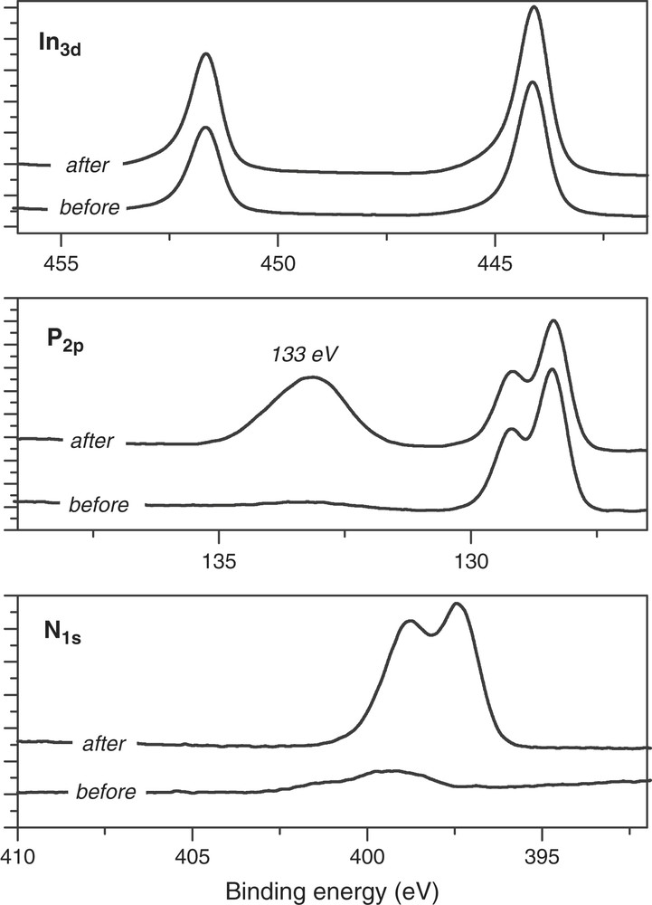
Comparison and evolution of XPS spectra before and after recording the anodic wave in liquid ammonia by cyclic voltammetry.
A thin film involving phosphazene termination was evidenced by XPS analyses and stability tests [9,10]. A complete recovering of the surface by the passivated film was evidenced by the immunity of InP in the air.
At the opposite, the current–voltage curve in NH3 liq. of a sample entirely covered by InPO4 oxides was drastically modified under illumination (Fig. 3H). A null current intensity was recorded from −0.5 to 1.1 V. No anodic wave was therefore observed. As a main result, InPO4-like oxides are highly stable in NH3 liq. since the anodic wave was not detected, like onto a bare InP surface (Fig. 3A). The null current value revealed that the blocking properties of InPO4-like oxides were still efficient in NH3 liq., like it has been demonstrated in aqueous solution [6,8,12]. XPS spectra identical to those observed in aqueous solution (Fig. 2) were obtained after recording this current–voltage curve (Fig. 3H). From the aqueous process, a complete oxide covering surface was clearly required, since no phosphazene terminations on the surface were detected by XPS (Fig. 2). As a consequence, NH3 liq. behaved like an inert electrolyte on a sample entirely covered with InPO4-like oxides.
Compared to the two previous voltammograms, the current–voltage curve recorded under illumination, in NH3 liq., on a sample partly covered with oxide islands was also very singular (Fig. 3C). A very small anodic wave centered at −0.1 V was observed with an anodic charge close to 0.5 mC cm−2. To contrast with the whole wave recorded on the bare InP surface (Fig. 3A), only a partial anodic wave was described (Fig. 3C). This loss of coulometric charge revealed once more both the stability and blocking properties of indium–phosphate phases, even at an island stage. In this case, the InP surface (noted InP–C), presents obviously zones covered and uncovered with InPO4-like oxides. We can then assume that the anodic response in NH3 liq. results from uncovered InP surface. As a consequence, uncovered zone on InP should be available to perform the anodic passivation in liquid ammonia, according to the Eq. (2). Thus, phosphazene terminations onto uncovered oxide zone should be expected. To confirm this assumption, XPS measurements have been performed and analyses were reported in Fig. 5.
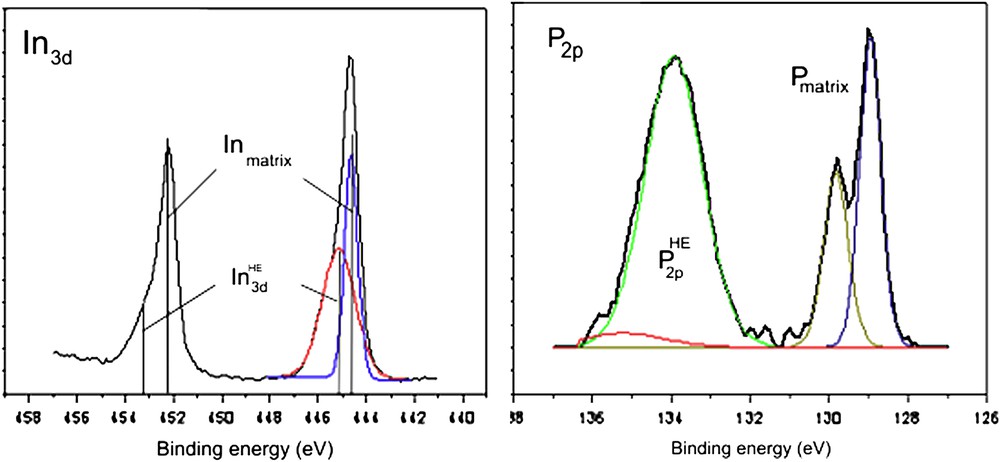
XPS spectra after the anodic treatment in liquid ammonia on a sample partly covered with indium–phosphate-like islands. For visualizing colors, see the web version of this article.
3.3 Evidence of hybrid structures: “P–N” termination and oxide layer
XPS analyses have been performed after the anodic treatment in NH3 liq. on a InP surface partly covered with oxide islands (InP–C). For the indium and phosphorus components given in Fig. 5, In3d5/2, In3d3/2 and P2p peaks present again new contributions positively shifted at high binding energy (noted In3dHE and P2pHE), evidencing the presence of new phases. The In3dHE feature clearly fits with In atoms bounded to O atoms “In–O”, proving then the presence of InPO4-like oxide at the SC surface. This conclusion is confirmed by the lack of indium contribution involved in the phosphazene film in NH3 liq. (Fig. 4). Concerning the phosphorus element, the alternated electrochemical treatments may induce different terminations such as “P–O” or “P–N” (Figs. 2 and 4). The ratio of the peak areas of In3dHE/P2pHE was moreover higher than 1. This ratio increase indicates that the InPO4-like phase is not the only contribution on the surface. As a consequence, the increase of the phosphorus contribution at high binding energy (P2pHE) then requires the presence of both “P–O” and “P–N” bonds. The P2pHE feature also fits with P atoms bounded to N atoms, “P–N”, detected on phosphazene terminations (Fig. 4). The “P–N” surface terminations were confirmed by an increase of the nitrogen contribution like the one evidenced in phosphazene film (Fig. 4). “P–N” surface terminations were also in agreement with the small anodic wave recorded in NH3 liq. (Fig. 3C).
4 Conclusion
The reproducibility of both current–voltage curves in NH3 liq. and XPS analyses prove that an alternated treatment of anodizations in two contrasted electrolytes was efficient. This alternated treatment from aqueous buffered medium (pH 9) reveals the great stability of InPO4-like oxides whatever the oxide coverage step. The blocking properties of InPO4-like oxides were also confirmed in liquid ammonia. As a main result, a chemical surface including oxide contribution and specific “P–N” surface bond chemistry was evidenced on a surface partially covered with InPO4-like oxides. The “P–N” surface terminations should then offer new possibilities for further high-speed optoelectronic applications. By varying the covering level of the two kinds of anodic layers, different hybrid structures should be obtained. Localized functional molecular grafting on InP should be carried out according to the hybrid structure.