

1 Introduction
Indium phosphide is an attractive material for high-speed optoelectronic devices. Its integration in electronic devices is, however, still complex due to chemical instabilities of the InP surface. In aqueous media, many works have been performed to control the growth of different kinds of oxide structures on InP by electrochemistry [1–4]. In particular, at pH 9, the growth and formation of thin InPO4-like anodic films has been evidenced [5–8]. According to the anodization parameters (i.e. current density and treatment time), the oxide coverage could be controlled from an island stage up to a complete covering by a homogeneous layer with good electrical blocking properties [6,8].
However, the etching of the oxide layer becomes also a crucial step when no interesting properties are evidenced. The dissolution of the semiconductor (SC) involves generally its oxidation. Two mechanisms are distinguished: either an electrochemical oxidation or a chemical oxidation process. Both techniques have made a significant contribution to the research and development of III-V devices [4,9]. In practice, the chemical etching is still a complex multi-step reaction involving surface bonded atoms. In addition, a strong anisotropy is often observed [10]. This process inhibits, then, a homogeneous dissolution of the oxide surface. In contrast to the chemical process, the electrochemical technique involves the injection of holes in the valence band of the semiconductor [11]. The electrochemical process can be performed in two ways. The first way involves the polarization of the interface SC/electrolyte using an external circuit. The second requires a strong oxidizing agent in solution. Since this electroless method does not require an electrochemical cell and voltage source, it is more attractive for many applications [4].
This work is a further contribution to this research. This study is divided in two parts. In the first part, the formation of an oxide on InP is controlled using an electroless process in aqueous solution. In the second part, the chemical stability of the resulting oxide is studied in liquid ammonia (NH3 Liq.) against the strongest reducing agent: the solvated electron.
2 Experimental part
InP-n semiconductor wafers with a <100> orientation were purchased from InPact Electronic Materials, Ltd. A doping density of 1018 cm−3 was used. The wafers were cut into small squares (0.5 × 0.5 cm2). Prior to use, semiconductors were chemomechanically polished with a solution of bromine in methanol (10%), and rinsed with purest methanol and dried under an argon stream [6–8]. In order to remove residual oxides, samples were dipped for a few minutes in 2 M HCl [6–8,12]. In aqueous media, potassium ferricyanide (3 × 10⁻¹ M) was dissolved in alkaline solution (pH 9). This solution was the oxidizing electrolyte. The electrochemical studies were performed in a borate buffered Tritisol (Merck) solution at the same pH, using a classical three-electrode device. The mercury sulfate electrode (MSE = +0.65 V/SHE) was used as a reference electrode and a large Pt electrode as a counter electrode. Capacitance-measurements versus potential, (C-V), were used to probe the oxide covering on InP. Differential capacitance voltage (C-V) measurements were carried out in the dark, after the oxidation treatments of InP in the oxidizing electrolyte (pH 9). The sinusoidal modulation frequency was set at 1107 Hz.
Ammonia (electronic grade) was purchased from Air Liquide. The cell and equipment for condensing ammonia have already been described [13]. The volume of liquid ammonia was approximately 150 cm3 and the cell was maintained at 223 K in a cryostat. The neutral media was obtained by addition of KBr (0.1 M) providing also the conductivity of the electrolyte. All potentials were measured vs. a silver reference electrode (SRE) [14]. The deaeration of the medium was performed under an argon stream. The electrochemical set-up was also a classical three-electrode device, using a PARSTAT 2273 potentiostat. Solvated electrons were obtained from two mechanisms. The first was the reaction of an alkali metal (potassium) with liquid ammonia [15]. The second was a cathodic galvanostatic treatment on InP in neutral medium [16]. X-ray photoelectron spectroscopy analyzer (XPS) were performed on an Escalab 220 i XL, V.G. spectrometer. A focused monochromated X-ray beam (Al Kα) was used for excitation. For detection constant analyzer energy mode was used, with pass energy of 8 or 20 eV. Photoelectrons were collected perpendicularly to the surface. Calibration of the spectrometer was done using the E902-94 ASTM procedure. The surface roughness was characterized by AFM using a contact and mapping mode (D300, Digital instrument, WsXM software). Each stage was analyzed: the initial surface of InP, the oxidized InP surface and after solvated electrons effect on the oxidized InP surface.
3 Results and discussions
The ferricyanide ion was used as a strong oxidizing agent in alkaline solution at pH 9. This oxidizing agent was reduced by injections of holes in the valence band of InP [4,7]. In parallel, the oxidation of InP was then resulting from the migration of holes to the surface due to the electrical field on the space charge layer. By damping the semiconductor in the potassium ferricyanide solution, InP was oxidized from one hour to 16 hours. This open circuit oxidation of InP was a really attractive process since no electrochemical cell and voltage source were required. The sample was properly removed from the potassium ferricyanide solution (pH 9) to a buffered borate electrolyte (pH 9). Before this transfer, a rinsing step of InP with deionized water was required to avoid a contamination from ferricyanide ions. The oxide on InP was characterized by capacity measurement using Mott-Schottky relation (C−2 = f(V)). During the capacity measurements, a potential drop across the oxide/InP interface. The variation of the potential was used as an in situ probe of the oxide density on InP. Before and after InP oxidation, a parallel positively shift of C−2(V) plots was observed. A significant variation of the flat band potential (≈ 400 mV) was evidenced, with a good stability over time (Fig. 1). The linearity of the plots is kept until 30 min. The linearity of C−2 (V) plots suggests that only a modification of the space-charge capacitance could explain dependences of C−2 (V) [4]. However, we cannot omit that an extra potential drop can appear in the oxide layer or in the Helmoltz layer [4–11]. This phenomenon has already been observed on InP using also a buffered solution at pH 9 [7]. The parallel shift of C−2 (V) plots was associated to the formation of oxide islands on InP. However, some deviation from the linearity was observed for a longer time (1 and 16 h). This behavior can suggest a limitation of growth oxide on InP [7]. The surface of InP can be entirely covered with oxide. A notable modification of InP surface was then revealed after the electroless oxidation process. From constant capacity measurements, a good stability of this surface modification was evidenced.

Mott-Schottky interfacial capacitance (C−2 = f(V)) on n-InP in alkaline buffered aqueous solution at pH 9 in the dark. t0: initial state of the surface. t “0x”: after the oxidation treatment of InP surface (1 h) in the ferricyanide aqueous solution at pH 9. Resulting C−2 = f(V) for different period in the buffered solution (: 15 min, +: 30 min, : 1 h, ○: 16 h).
In order to reveal this surface transformation, the chemical composition of the surface was analyzed by X-ray photoelectron spectroscopy (XPS) (Fig. 2). Reproducible In3d (In3d5/2 and In3d3/2) and P2p (P2p1/2 and 2p3/2) photoelectron peaks were obtained for different samples. In3d and P2p peaks were compared before and after the oxidizing treatment on InP. New contributions, positively shifted to higher energy were observed for In3d and P2p. They were associated with oxidized phases on InP such as InPO4 like oxide. O atoms were bounded to In (Inox) and P (Pox). From indium peaks analyses, the ratio between the oxidized contribution (Inox) and In matrix was equal to 3.53. From phosphorus peak analyses, the ratio between the oxidized contribution (“Pox”) and P matrix was equal to 1.31. As a result, the InP surface was clearly oxidized after damping the sample in the potassium ferricyanide solution.
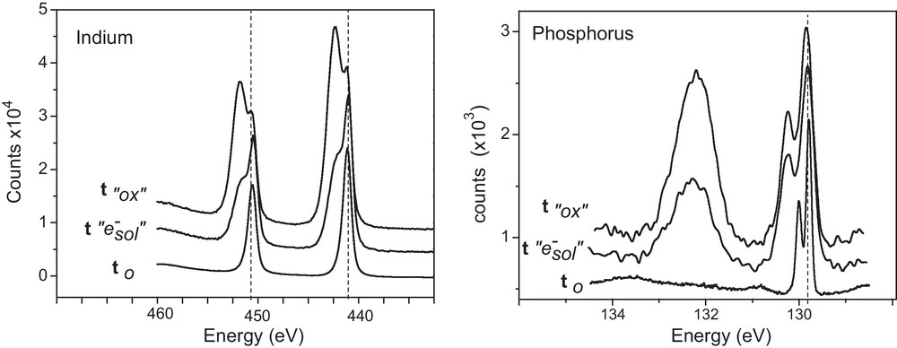
Comparison and evolution of XPS spectra surface (In3d, P2p) analysed on n-InP: t0: initial state of the surface. t “0x”: after the oxidation treatment of InP surface (16 hours) in the potassium ferricyanide aqueous solution at pH 9. t “e−sol”: After exposure time of solvated electrons by cathodic galvanostatic treatment (J = −1 mA.cm−2, t = 600 s) in neutral NH3 liq. (T = −55 °C) added with 0.1 M KBr.
The chemical stability of the oxidized surface of InP was investigated against the strongest reducing agent in NH3 Liq.: the solvated electron. Several attempts were made. The first try was an electroless process. A piece of metallic potassium was added in liquid ammonia. A typical blue dark color of solutions of metallic potassium spontaneously arose from the presence of solvated electrons dissolved in NH3 Liq. [15]. As long as no contaminants were present in NH3 Liq. solvated electrons were classically stable for days [15]. Before the blue dark coloration disappeared, the oxidized surface of InP was immersed 30 min in NH3 Liq. In fact, removing the semiconductor from NH3 Liq. was a complicated process due to the large change of temperature from very low value (223 K) to room conditions. In order to analyze the resulting chemical composition of the surface by XPS, the sample was properly removed from the solvent and rinsed in pure NH3 Liq. Despite an in situ gradual increase of the temperature, the InP surface was surprisingly more oxidized than before contact with solvated electrons. This result could be explained by the strong reactivity of solvated electrons with oxygen during the gradual increase of the temperature to the room condition. The second try was the formation of solvated electrons by electrochemistry in NH3 Liq. The neutral medium in NH3 Liq. was provided by the addition of potassium bromide salt (0.1 M) [16]. In contrast to other solvents, even non-aqueous solvents, no hydrogen evolution was observed for high cathodic overvoltage in NH3 Liq. in neutral medium. By opposition the electrochemical formation of solvated electrons was detected at −2.4 V vs. SRE. Contrary to the electroless process (metallic potassium addition), the electrochemical formation of solvated electrons was controlled by the applied potential or by the applied current density. A galvanostatic process was hold at the interface using a current density of −1 mA.cm−2 during 600 s (Fig. 3). According to the applied current density, a potential impulsion was observed until reaching a constant potential level at E = −2.4 V versus SRE (Fig. 3). This potential was associated to the electrochemical formation of solvated electrons [13,16]. A good stability of the interfacial potential (E = −2.4 V vs. SRE) was observed during the galvanostatic process (Fig. 3). The InP surface was also characterized by capacity measurement using Mott-Schottky relation (C−2 = f(V)) before and after the electrochemical formation of solvated electrons (Fig. 3, insert). A significant variation of the flat band potential (≈ 700 mV) was evidenced after the galvanostatic process corresponding to a cathodic charge of 0.6 C.cm−2 (Fig. 3 insert). It is important to note that the Mott-Shottky slope was maintained but now negatively shifted. In contrast, in alkaline aqueous medium, during the formation of the InP oxide, the slope was positively shifted (Fig. 1). We can assume that an in situ partial recovering of the surface could be occurred after the electrochemical formation of solvated electrons.
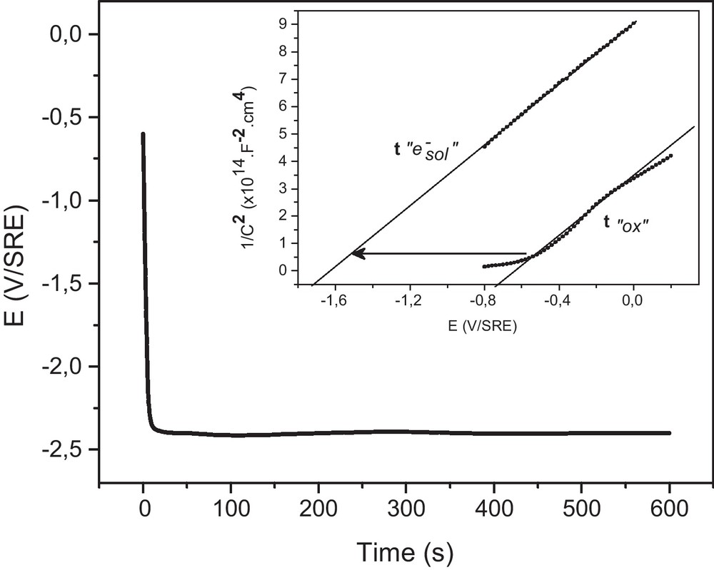
Electrochemical formation of solvated electrons (E = −2.4 V vs. SRE) by galvanostatic treatment (J = −1 mA.cm−2, t = 600 s), on n-InP in neutral NH3 liq. (T = −55 °C) added with 0.1 M KBr. Insert: Mott-Schottky interfacial capacitance (C−2 = f(V)) on n-InP in neutral NH3 liq. (T = −55 °C) added with 0.1 M KBr. t “0x”: after the oxidation treatment of InP surface (16 h) in the ferricyanide aqueous solution at pH 9. t “e−sol”: After the formation of solvated electrons by galvanostatic treatment (J = −1 mA.cm−2, t = 600 s) in neutral NH3 liq. (T = −55 °C) added with 0.1 M KBr.
In order to analyze the resulting chemical composition of the surface by XPS, the sample was properly removed from the solvent and rinsed in pure NH3 Liq. In3d and P2p peaks were compared before and after the electrochemical formation of solvated electrons on InP. For both components, the oxidized contributions (high energy) were drastically decreased. From indium peaks analyses, the ratio between the oxidized contribution (Inox) and In matrix decreased from 3.53 to 1.18. From phosphorus peak analyses, the ratio between the oxidized contribution (Pox) and P matrix decreased from 1.31 to 0.61. As a result this electrochemical process has improved significantly the recovering of the initial surface.
The roughness of the surface at the different steps of modification has been characterized by AFM. Fig. 4 shows characteristic images before any treatment (a), after the oxidizing treatment (b) and after the treatment by solvated electrons (c). The corresponding profiles are also shown (d, e, f) along the lines drawn on the images and give a clear idea of the mean roughness of each surface. Using WsXM software, the roughness average has been determined for each surface. Without oxide, a low surface roughness was observed on the initial surface of InP (Fig. 4a) and an average roughness of 0.7 nm is obtained. After the overnight oxidizing treatment in alkaline aqueous medium (pH 9, 16 h) by the potassium ferricyanide solution, the roughness increases significantly (Fig. 4b) to reach an average roughness of 12.5 nm. A clear decrease of the roughness is observed after the action of solvated electrons produced by galvanostatic treatment (Fig. 4c). The roughness average for this last surface appears to be around 4 nm. It is noticeable that the surface roughness remains higher than the one observed on the initial state. Solvated electrons apparently removed some of the peaks formed by the oxidation without reaching the initial flatness. Nevertheless, Fig. 4f shows that the roughness between the remaining peaks appears as low as the roughness of the initial one (Fig. 4d).
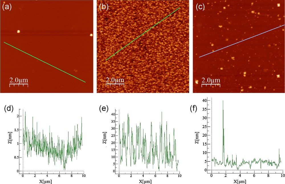
10 × 10 μm AFM images (a, b, c) and their corresponding profile lines (d, e, f) of n-InP surfaces at different steps of the treatment. (a) t0: initial state of the surface, (b) t “ox”: after oxidation of n-InP in the ferricyanide alkaline solution at pH 9 (16 h). (c) t “e−sol”: after the effect of solvated electrons produced by galvanostatic treatment (J = −1 mA.cm−2, t = 600 s) in neutral NH3 liq. (T = −55 °C) added with 0.1 M KBr.
4 Conclusion
In ferricyanide alkaline aqueous solution, the electroless formation of an oxide on InP was successfully controlled by capacity measurements and XPS analyses. An oxidized phase such as InPO4 like oxide was formed on the surface after the oxidizing treatment. For the first time, its chemical stability was analyzed against the strongest reducing agent in liquid ammonia (−50 °C): the solvated electron. Due to the high reactivity of solvated electrons, the electroless process, involving the addition of metallic potassium, was not efficient. The electroless process should be improved by a better rinsing step to remove solvated electrons from InP surface. In contrast, a better exposure time of solvated electrons was controlled by a cathodic galvanostatic process, in neutral medium in NH3 Liq. A low cathodic charge (600 mC.cm−2) was sufficient to recover partially the Mott-Schotky plots. The reduction of the oxide phase on InP was suggested by in situ capacity measurements. This result was then confirmed by ex situ experiments. A significant decrease of the amount of oxide was indeed evidenced by XPS analyses. After the effect of solvated electrons the roughness of InP was also decreased. The electrochemical process could be improved by increasing the duration of the galvanostatic process or the applied current density.