

1 Introduction
Chemical shapes and functionalities are certainly the two most important tools employed toward the reaction schemes of living organisms. Historically, chemical science first addressed and was interested in the composition of matter rather than its shape. Indeed, it is only in the middle of the XIX century that the notion of “isomers” has emerged when the chemical structure formulae replaced the global one. The notion of shape is becoming more and more important in chemical science. For instance the notion of key/host when addressing dynamic combinatorial chemistry is extensively employed when dealing with supramolecular chemistry [1a]. Another good example relies on the carbon case where fullerenes, graphenes and nanotubes bear divergent properties when compared with the basic graphite or diamond allotropic forms.
Today, society high standard specific needs are pleading for chemists to conceive entities more and more complex, multi-scales, multifunctional and capable of developing a certain degree of autonomy, taking inspiration from Mother Nature. The chemical paths employed to generate such complex architectures are becoming more and more complex and certainly interdisciplinary, bio-inspired or not. When considering the field of bio-inspired materials “integrative synthesis” has been first proposed by S. Mann [2] while coupling transcriptive, synergistic and spatially restricted syntheses. This approach was further refined by C. Sanchez [3] who summarized perfectly the outstanding revolution in modern materials chemistry. This concept was finally fully theorized when enouncing the concept of “Integrative Chemistry” [4] as “the integration of the sol–gel process, inorganic chemistry, lyotropic mesophases, supramolecular architectures, air-liquid foams, biliquid foams, external fields, organic polymers, nanofunctionalization and nanotexturation, (...) [, which] offers the possibility of achieving new architectures at various length scales and with enhanced properties.” Hence, Integrative Chemistry can be understood as a method for material design where the initial bricks, relevant from several domains of chemical sciences, are connected and assembled with the help of different driving forces occurring via multi-scale reactions and structuring mechanisms. In this regard and conceptually speaking, Integrative Chemistry [3] is certainly the link between the notions of “complexity in chemistry” [5] and the bio-inspired integrative synthesis [1,2]
The goal here is certainly not of being exhaustive considering the design of advanced functional materials, but more importantly to depict how Integrative Chemistry allows positioning chemical reactors within the geometric space. For this purpose we will drive the discussion with material morphosyntheses when using only emulsions, either direct or reverse, diluted or concentrated, as tools to shape final material shapes, sizes and morphologies.
2 General background
2.1 Emulsions and their oil/water interfaces employed as chemical reactors at a glance
Emulsions are thermodynamically meta-stable: over time, the dispersed and continuous phases will macroscopically segregate. They are typically classified into two categories: water-in-oil (W/O) also called reverse emulsions and oil-in-water (O/W) also called direct emulsions (Scheme 1) [6].
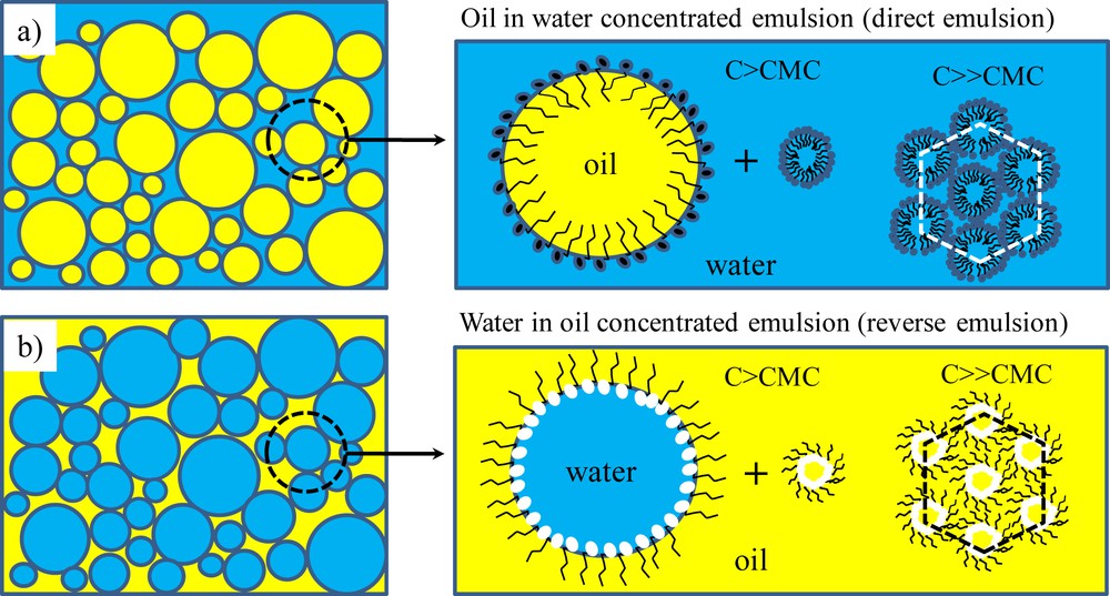
Schematic representation of: a) oil-in-water concentrated emulsion where oil droplets are dispersed within a continuous aqueous phase, b) water-in-oil concentrated emulsion where water droplets are dispersed within a continuous oily phase. The hydrophilic or hydrophobic continuous phase will contain respectively direct or reverse micelles, a micelle being a supramolecular self-assembly of surfactant entities. For high micellar concentrations, these micelles will self organize within lyotropic mesophases, and hexagonal phases in the present case.
To enhance their thermodynamic stability, surfactants are traditionally employed to stabilize the interfaces. As shown in Scheme 1 those surfactant molecules made of a polar head group and a hydrophobic chain will take position at the oil/water interface to minimize the interfacial energy. The choice of the surfactant is important: the Bancroft rule states that a surfactant bearing the higher affinity with one phase will promote this phase as the continuous one [7]. Most of the time the micelles will be swollen with a small amount of the disperse phase, creating a micro-emulsion (nanometer length scale) which is thermodynamically stable contrary to a macro-emulsion (micrometer length scale). Considering their use as soft templates, these concentrated micro-emulsions will promote a second porosity, called mesoporosity, within the final monolithic materials when calcinated. If the wall skeleton is amorphous as it is the case for silica or polymers, final materials will bear intrinsic microporosity, leading overall to a hierarchical porosity. As depicted in Scheme 2, the oil/water interface is crucial when addressing chemical reactions within the continuous phase.
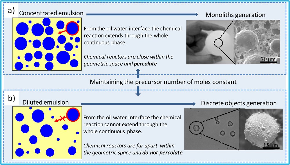
Effect of the starting emulsion concentrations over final material morphologies. a) Starting from concentrated emulsions, the oil/water interfaces acting as chemical reactors allow their percolation within the geometric space leading to monolithic porous materials when chemical reactions occur. b) Starting from diluted emulsions the oil/water interfaces are spread within the geometric space and the associated chemical reaction cannot percolate, leading this time to discrete capsule generation when chemical reaction occurs.
From a chemistry point of view, we can distinguish concentrated and diluted emulsions. Indeed everything relies on the repartition of the oil/water interfaces that will act preferentially as chemical reactors. When promoting nucleation and growth within the continuous phase, the nucleation will always start preferentially at these interfaces, because they represent defects at which the associated heterogeneous nucleation enthalpy is strongly minimized when compared with the bulk homogeneous one. Still from a thermodynamic point of view, the interfaces (Scheme 1) bear high charge density that will favor the under growing nuclei electroneutrality, thereby optimizing both the nucleation and growth steps. Considering the oil/water interfaces as chemical reactors, when concentrated through the use of concentrated emulsion, the chemical reactors will percolate within the geometric space (Scheme 2a) promoting the generation of porous monolith-type materials, while when spread through the use of diluted emulsions, these chemical reactors cannot percolate anymore, leading this time to the generation of discrete capsules (Scheme 2b). It is this aptitude of positioning chemical reactors into the geometric space that will be illustrated hereafter when addressing the design of advanced functional materials.
2.2 Concentrated emulsion-based foams: polymer and ceramic at a glance
Foams are materials containing gaseous voids surrounded by a denser matrix, usually a liquid or a solid. The cells can be closed or open: in closed cell foams, the voids are isolated from each other and cavities are surrounded by complete cell walls whereas in open cell foams the structure consists mainly of ribs and struts. Polymer foams are the most common but their applications are limited by their inferior mechanical strength, poor surface quality and low thermal and dimensional stability. They are usually prepared by chemical or physical foaming [8], but the control of the cell size and morphology is difficult as well as the preparation of fully open-cell structures. Therefore, the emulsion-templated approach to prepare foams could present an interesting alternative. In this vein, High Internal Phase Emulsions (HIPEs) are a class of emulsions characterized by an internal phase volume fraction exceeding 0.74, which corresponds to the most compact arrangement of uniform, undistorted spherical droplets. Consequently, their structure consists of deformed (polyhedral) and/or polydispersed droplets separated by a thin film of continuous phase, a structure resembling gas-liquid foams.
Polymerization of the emulsion continuous phase and removal of the dispersed one, used as a soft template, lead to solid microcellular foams: emulsions are powerful tools to generate hierarchical porosity when combined with lyotropic mesophases, various synthetic routes have been reviewed recently by M. S. Silverstein [9]. The network precursors are generally a monomer or a mixture of monomers being often styrene divinyl-benzene [10] used as the continuous phase where water droplets are dispersed, this refers to reverse emulsion (see Scheme 1). Once radical polymerization occurs after a washing step we obtained a polymeric monolith bearing open cell porosity on the macroscopic length scale (Fig. 1).
A typical porous polyHIPE structure (SEM). John Wiley & Sons Copyright 2002.
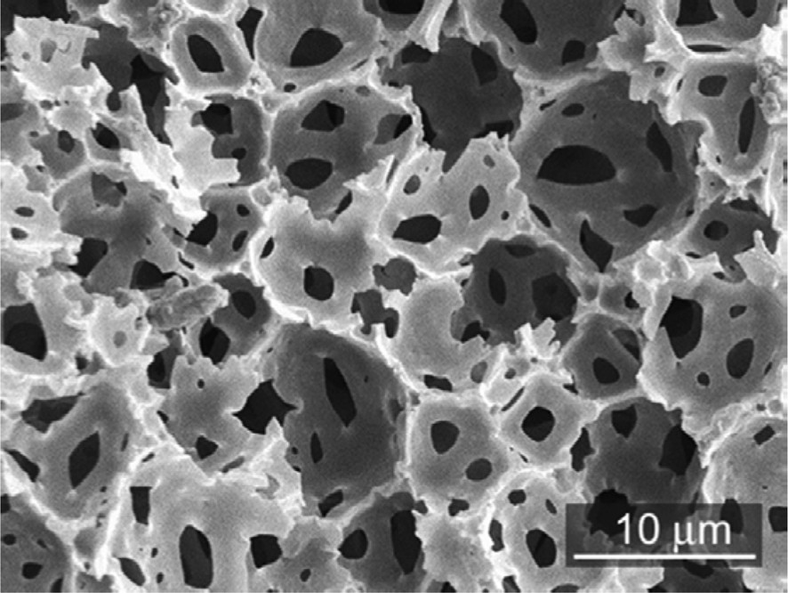
If silica precursors such as tetraethyl-orthosilane (TEOS) are used the materials synthesized will be called Si-(HIPE). The first step will be the hydrolysis of TEOS toward Si(OH)4, the silicic acid being the inorganic polymer precursor. Thereby the precursors being hydrophilic, this time oil droplet will be dispersed within the continuous aqueous one, we are now dealing with direct emulsions (dispersion of oil droplets in water), see Scheme 1. The Si-(HIPE) foams possess very high porosity and very low bulk density. The void size is usually situated in the microcellular range (1–100 μm). These materials will be used as supports for a wide range of applications. In order to tailor the macroporous solids for different applications, it is important to be able to modify the macroscopic void space diameters (Fig. 2). Varying the starting oil volume fraction (ϕo) of an oil-in-water concentrated emulsion [11] is one way to achieve that. Note that generally varying the oil volume fraction also modifies the initial drop size. Several O/W emulsions with increasing oil volume fractions (1Si-HIPE, ϕo = 0.70; 2Si-HIPE, ϕo = 0.73; and 3Si-HIPE, ϕo = 0.78) have been prepared and the resulting solid foams analyzed. Whatever the oil volume fraction, the general texture resembles aggregated hollow spheres. The macrocellular void sizes of the resulting material diminish drastically because the viscosity of concentrated oil-in-water emulsions increases dramatically when the oil volume fraction reaches values above 0.64 [12], the random close packing of monodisperse spheres. The enhanced viscosity of the emulsions increases the shear applied to the droplets, thus inducing smaller macrocellular voids within the silica replica. These porous materials possess a secondary micro-mesoporosity, due to the lyotropic mesophase as explained previously. It translates in specific surface areas values (BET) values of around 800 m2 g−1. It is possible to align the macropores by using a hydrophobic ferrofluid instead of oil and applying an external magnetic field during the condensation process [13].

SEM visualization of the inorganic monolith-type material macrostructure. a) and b) 1Si-HIPE, c) and d) 2Si-HIPE, e) and f) 3Si-HIPE. RSC Copyright 2004.
3 Hybrid and carbonaceous foams
3.1 Hybridization of Si(HIPE)
3.1.1 Eu3+@Organo-Si(HIPE): photonic properties
The design of efficient lanthanide complexes as molecular devices became an important issue in the 1990s since Lehn [14] proposed the chelation of lanthanide ions with different ligand families for their photophysical properties. We prepared [15] luminescent foams either via a two-step process in which β-diketone or malonamide organosilane derivates were grafted to a previously prepared macrocellular Si-HIPE or via a “one-pot” co-condensation of the silica precursor (TEOS) and a trialcoxysilylated β-diketone precursor. Each synthetic pathway led to self-standing monolithic materials showing luminescence properties upon UV light exposure. As an example, the spectra registered for the Eu@β;-diketone-Si(HIPE) sample is shown in Fig. 3. They consist of a set of emission lines corresponding to the intra 4f electronic transitions from the lowest excited state, 5D0, to the ground state manifold, 7FJ (J = 0–4). This is interesting for the design of light emitting devices since the aim is to find a high efficiency in the photoluminescence emission spectra.
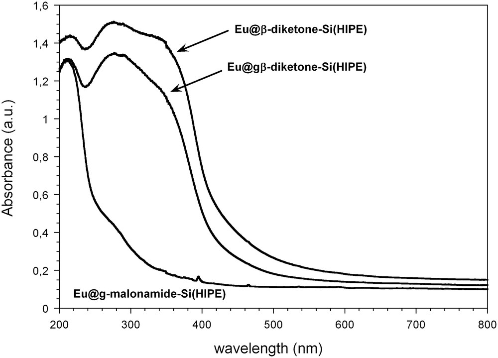
Excitation spectra of the Eu-doped organically derived Si(HIPE) hybrid materials monitored the Eu3+ emission at 615 nm. ACS Copyright 2008.
We have now extended this work where light transport is directly tuned by the type of macroporosity. The light mean free path through the foams is correlated with the void diameters and the wall refractive index, by tuning the macroscopic void diameters we were able to trigger for the first time a competitive scenario between random lasing and stimulated Raman scattering [16].
3.1.2 Pd@Organo-Si(HIPE) and enzyme@Organo-Si(HIPE) : heterogeneous catalysis properties
Palladium heterogeneous nucleation within the macrocellular Organo-Si(HIPE) materials has been performed (Fig. 3a) [17]. The resulting supported catalysts are called Pd@gAmino-Si(HIPE), Pd@gMercapto-Si(HIPE) and Pd@Mercapto-Si(HIPE) depending on the starting Organo-Si(HIPE) employed [18]. These materials were tested as catalysts for the Mizoroki–Heck reaction between iodobenzene and styrene followed by GC. High selectivity is observed in all cases for the E product isomer (E/Z: 96/4). Conversion is always close to completion (Fig. 4), but supported catalysts bearing a mercapto group appear to be less sensitive to deactivation/leaching than those functionalized with an amino group. These results seem to confirm the previously reported observation that mesoporous silica modified with a mercapto-propyl group provides good scavenging properties toward Pd nanoparticles, thus reducing leaching [19]. Runs were pursued with Pd@Mercapto-Si(HIPE), showing a slow decrease in conversion yield from 92 to 75% for the eighth and ninth run, respectively. To investigate the influence of Pd loading the Pd/iodobenzene molar ratio was set at 0.002 or 0.004. TON (turn over number) and TOF (turn over frequency) values obtained reach the best results for silica-based supports considering the work of Crudden et al. [20]. In order to reach more sustainable chemistry, we have focused our research toward enzyme-based catalysis. One drawback when increasing the stability of an enzyme using a confinement process is the associated decrease of accessibility and diffusion. Hence to design high-performing heterogeneous bio-catalysts one has to balance each aspect of the material [4].

Cycling Heck coupling reactions and conversion yields. ■ Pd@gAmino-Si(HIPE), ● Pd@gMercapto-Si(HIPE), △ Pd@Mercapto-Si(HIPE) and Pd@gAmino-Si(HIPE), in this case, 0.055 g of support were used instead of the 0.11 g used for all the other tests. Conversion yields are the average of two GPC analyses. ACS Copyright 2008.
Among the possible strategies, immobilization and encapsulation of enzymes within sol–gel derived matrices [21–24] have been studied due to the great potential applications as biocatalysts [25] and biosensors [26]. (3-Glycidyloxypropyl)trimethoxysilane (Glymo) is used as a functional agent to stabilize the embedded enzymes. Using crude Candida rugosa, the catalyst was able to cycle for 19 runs with 100% conversion until a small decrease of the catalytic activities for runs 20 and 21 (Fig. 5), due to the monolith partially collapsing [27]. The same experiment in a homogeneous batch does not lead to complete conversion even after 24 h, so these results are due to the bio-hybrid catalyst design. The catalyst was put at 4 °C for two months between cycle 10 and cycle 11, and as it can be seen from Fig. 5 did not lose any catalytic activity. Compared with other enzyme-based heterogeneous catalysts [28–30], this one has high esterification catalytic performances, associated with higher stability in time. It is also possible to use our catalyst for hydrolysis and trans-esterification, with outstanding TOF and TON, while opening the door for continuous heterogeneous biocatalysis [31].
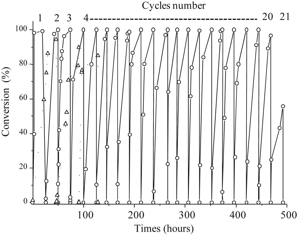
Candida rugosa based heterogeneous catalyst performance. [C-CRl]@Glymo-Si(HIPE) toward esterification reactions: Glymo stabilized enzyme, ▵ whithout Glymo. ACS Copyright 2010.
Considering the catalysis reactions described above, they are all addressed at the surface of macropores, nothing is confined within the mesoscopic voids while offering outstanding TON and TOF. The remaining question is why such high efficiency while not using either the mesoscopic voids neither the microporous ones? Indeed the fluid behavior within macropores is depicted in Scheme 3. As the fluid convection mode is addressed through a Poiseuille flow (fluids employed in catalysis being Newtonian, their viscosity remains constant under shear) the fluid hydrodynamics will impose a gradient of speed within the macropore (Scheme 3) [18].
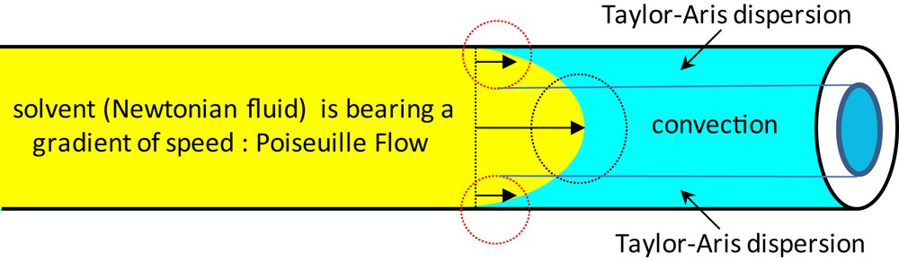
Fluid hydrodynamics within a macropore bearing a convection mode at the center and a Taylor–Aris dispersion mode at the interface.
It means that the fluid behavior within the macropore is intrinsically and hierarchically organized. At the macropore centers, the fluid flow will be driven by convection, while at the solid–liquid interface the scenario is the one of a liquid bearing a low but not negligible convection in which molecules are diffusing, this is to say a dispersion behavior, well known for the interface as the Taylor–Aris dispersion [31]. Our group was the first to address the above scenario revisiting completely the view of performing highly efficient heterogeneous catalysis while extending this approach toward enzyme-Si(HIPE)-based continuous uni-axial catalysis [27,31]. Overall, by performing heterogeneous catalysis within modified Si(HIPE) foams the low Fick diffusion is completely circumvented while all the catalytic species (even at the colloid length scale, like enzymes) can be reached at ease.
3.2 Carbonaceous (HIPE) using Si(HIPE) as the hard template
Hard templating [32] uses preformed hard porous templates impregnated with a carbon source that is subsequently carbonized under a non-oxidative atmosphere. After dissolution of the template, a carbonaceous replica is obtained. Ordered mesoporous carbons (OMC) have been synthesised by the insertion of carbon precursors within mesoporous silica particles [33–36]. Later on, Si(HIPE) materials (Fig. 6a, d) have been used as templates to generate carbon monoliths bearing macroporous interconnected void spaces (Fig. 6c, e) [37].
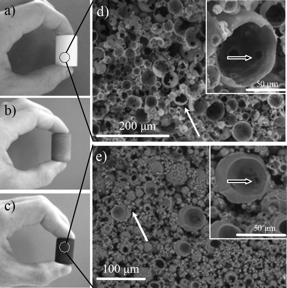
a) Silica porous Si(HIPE) template, b) typical cross-linked precursor/silica template hybrid composite, c) resulting carbon material after carbonization and silica removal. SEM micrographs, d) silica porous Si(HIPE) template, e) resulting carbon material after carbonization and silica removal by HF treatment. The white arrows indicate cells' external junctions, the black arrows indicate cells' internal junction. Wiley Copyright 2009.
After reticulation of the phenolic resin used as a carbon source, the samples were either treated with HF to eliminate silica and then pyrolised (Xcarb samples, where X is the starting weight percent of the resin) or pyrolised and then treated with HF (XHF samples). Fig. 6a–c show that the external shape of the matrix is maintained from the pure inorganic Si(HIPE) (a) to the macrocellular carbon monolith (c), via the reticulated polymer/SiO2 hybrid composite (b).
3.2.1 Carbon(HIPE) as Li-ion negative electrodes
Carbon(HIPE) materials have been tested as Li-ion negative electrodes. The voltage capacity curve of the 80HF sample is depicted in Fig. 6. The capacity delivered during the first discharge is around 900 mAh/g with a sloppy plateau at 0.8 V vs. Li+/Li(0) representing 500 mAh/g followed by a second discharge plateau at 0.2 V. On recharge 280 mAh/g is recovered, which is close to the classical capacity obtained with graphite electrodes. Fig. 6 shows that a strong difference between charge and discharge (around 70%) for the first charge–discharge cycle is occurring. This is explained by residual hydroxyl groups coming from the carbon precursor, which are known to induce this phenomenon [38], and from the decomposition of the electrolyte at the surface of the carbon resulting in the formation of a passivation layer or a Solid Electrolyte Interphase (SEI). A high surface area like in the 80HF sample means more surface is available to be passivated hence a high quantity of lithium is irreversibly consumed, leading to a large irreversible capacity (Fig. 7).
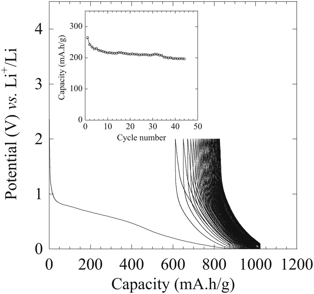
Potential-specific capacity curves of electrodes based on HF80 in the lithium metal battery configuration. Electrochemical tests were realized using a potential window between 0 and 2 V vs. Li+/Li0 and at a cycling rate of C/10. Wiley VCH Copyright 2009.
A good ability to cycle is still obtained and is stable at 200 mAh/g during the first 50 cycles at a reasonable current density (C/10) (inset Fig. 7). Later on we have extended these carbonaceous foam applications toward lithium-sulfide (Li–S) battery electrode application reaching unprecedented remnant capacity when cycling, while optimizing their mesoporosity [39,40]. Beyond, considering the hierarchical porosity and associated low densities, our group was the first to state that remnant capacities should be expressed both per masse (mAh/g) and per volume (mAh/cm−3) to really assess the absolute electrode efficiency.
3.2.2 LiBH4@carbon(HIPE) for hydrogen storage and release
Borohydrides bear a high hydrogen content [41,42] which is particularly true for LiBH4 (18.4 wt% and 121 kg m−3 H2). The complete recovery of the hydrogen in LiBH4 remains however difficult as the dehydrogenation of LiH, formed as an intermediate decomposition product, occurs at high temperatures (above 600 °C) thereby limiting the hydrogen release to 13.8 wt%. Different carbon (HIPE) materials have been impregnated by an ethereal solution of LiBH4 to prepare LiBH4@Carbon(HIPE) samples with a 30% LiBH4/total weight loading. XRD diffractogram in Fig. 8 shows the influence of their microporosity on the LiBH4 crystalline character.
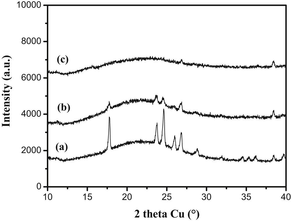
XRD of LiBH4@Carbon-HIPE with (a) 80HF, (b) 25carb, (c) 25HF porous carbons. The LiBH4 loading is about 30-wt% for all samples as verified by Li titrations. From (a) to (c) it can be seen that the crystalline character of the LiBH4 crystals is minimized through increasing the carbonaceous foam microporosity. RSC Copyright 2010.
An increase of the host microporosity induces an increase of the LiBH4 amorphous character. The nucleation certainly starts at the micropores present at the surface of the macropores, acting as defects where nucleation enthalpy is minimized. For the 80HF porous carbon, well-defined reflections assigned to the low-temperature orthorhombic unit cell of LiBH4 are observed (Fig. 8a) [43]. Moving to a larger microporous volume with the host labeled 25carb, the reflections are much weaker emphasizing a lower crystalline character (Fig. 8b). Finally in the 25HF sample (microporous volume about twice that of 80HF), any reflection corresponding to LiBH4 cannot be observed by XRD (Fig. 8c). In this sample, the microporous volume is highest and heterogeneous nucleation is enhanced as the high micropore concentration at the macroporous surface will favor nucleation at the expense of growth. The curves of hydrogen release (observed by mass spectroscopy) for the LiBH4@Carbon samples are presented in Fig. 9.
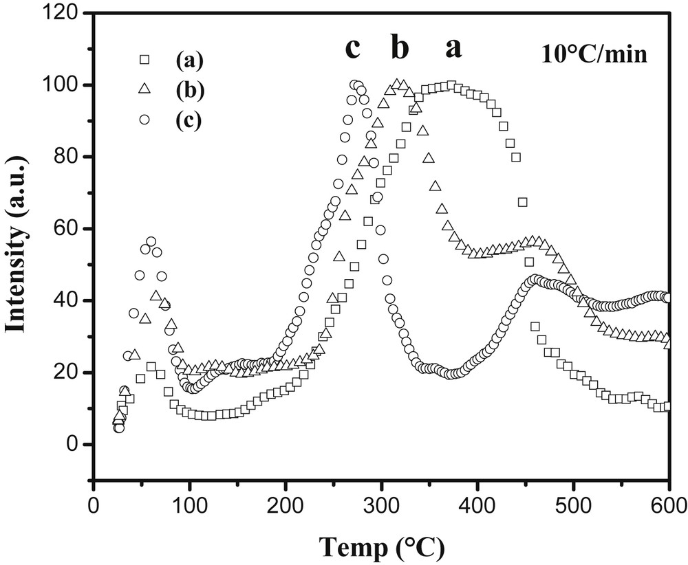
Curves of hydrogen release under primary vacuum of LiBH4@Carbon with (a) 80HF, (b) 25carb, (c) 25HF porous carbons as recorded by mass spectroscopy (m/z = 2). RSC Copyright 2010.
Dehydrogenation temperature is correlated with the microporous volume (Fig. 9): the more microporous the sample is, the lower the temperature at which it releases hydrogen and the thinner the hydrogen release peak is. This clearly shows that the dehydrogenation of LiBH4 can be finely tuned by modifying the porosity of the carbonaceous matrix, which modifies its crystallinity hence its stability. The issue of rehydrogenation still remains because of boron's intrinsic chemical inertness. To give cycling capabilities to these materials, palladium and gold nanoparticles have been introduced into the carbonaceous foam that had the best dehydrogenation performances, namely the 25HF sample, by a simple impregnation-reduction process [44]. This led to the Pd@Carbon-HIPE(25HF) and Au@Carbon-HIPE(25HF) metallic nanoparticles bearing carbon foams. The addition of LiBH4 leads here to the samples thereafter named LiBH4-Pd@25HF and LiBH4-Au@25HF. As opposed to what was observed with the simple carbonaceous foam, LiBH4 does crystallize in these samples, which shows that the metallic nanoparticles interact with LiBH4 as heterogeneous nucleation sites. As there are less metallic nanoparticles than micropores, nucleation will be minimized and growth of LiBH4 will be optimized at the nanoparticle surfaces. In these cases, the samples were rehydrogenated under 100 bar H2 at 400 °C for 12 h while reforming bulk LiBH4 necessitates harsh conditions such as 600 °C and 350 bar H2, while it is clearly not possible to rehydrogenate bulk LiBH4 under these conditions. For example the LiBH4-Pd@Carbon-HIPE(25HF) retains a 7.4 wt% hydrogen release after five cycles, about half of its initial capacity (Fig. 10).
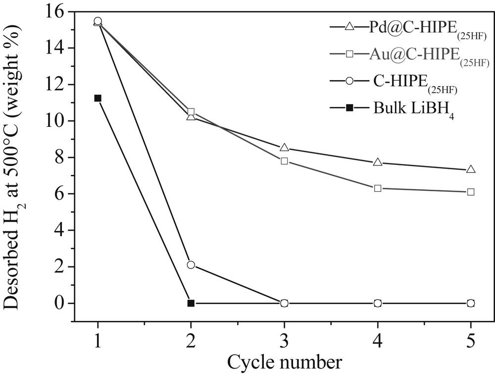
Amounts of hydrogen released for bulk LiBH4 and the LiBH4@carbon materials measured by the volumetric method for the first five cycles. The rehydrogenation is performed under 100 bar H2 at 400 °C for 12 h. RSC Copyright 2014.
Palladium and gold are not known to catalyze the rehydrogenation of LiBH4 and the complete mechanism is still to be understood. We have proven through 11B MAS NMR spectroscopy that gold and palladium nanoparticles promote the formation of BH4 environments free of oxidation, and thus promote LiBH4 heterogeneous nucleation and growth specifically on their surfaces, not on the carbonaceous walls anymore. Thereby, these metallic nanoparticle loaded carbonaceous foams have shown cycling hydrogen storage capacities and are promising candidates for further investigations. All the phenomenon occurs now at the surface of the macroporosity, having demonstrated now that Li(BH4) confinement within mesoscopic voids is not a sine qua non scenario for cycling borohydride hydrogen storage capabilities.
4 Pickering-based emulsions at a glance
As stated previously the emulsions used as templates are generally stabilized by surfactant molecules, the excess of them self assembling as micelles or mesophases in the continuous phase and at the origin of the mesoporosity. Surfactant molecules may be replaced by particles as first reported by Ramsden [45] and Pickering [46], provided these particles are partially wetted by both liquids. These emulsions are nowadays called Pickering or solid-stabilized emulsions and have regained a huge interest owing to their peculiar properties. The major difference with surfactant-stabilized emulsions is their outstanding stability due to the very high energy required to remove particles once anchored at the oil–water interfaces. Indeed even for small particles of the order of several tens of nanometers the desorption energy is of the order of several thousand times the thermal energy kB T [47]. A direct consequence of the strong particle anchoring at the interface is the possible use of a phenomenon called limited coalescence to produce monodisperse emulsions [48]. For this process to occur, particles have to strongly adsorb at the interface and to be present in a low amount, the so-called stabilizer poor regime (Scheme 4) to ensure complete and irreversible particle adsorption. Then emulsification results in producing a large excess of oil–water interface compared to the amount that can be stabilized by the solid particles. When the agitation is stopped, the partially unprotected droplets coalesce, thus reducing the total amount of oil–water interface. Since the particles are irreversibly adsorbed, the coalescence process stops as soon as the oil–water interface is sufficiently covered. Moreover the final drop size distributions of the as-obtained emulsions are much narrower than those of surfactant-stabilized emulsions obtained under the same stirring conditions [49].
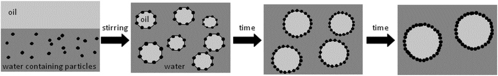
Schematic representation of the limited coalescence process. Stirring produces a large amount of oil/water interface and allows particle adsorption. After stirring cessation, insufficiently protected droplets coalesce reducing the total interfacial area. The phenomenon stops when the interface is sufficiently covered. Adapted from [47].
The resulting emulsions exhibit a drop diameter that is controlled by the mass of particles and their packing at the interface. The reverse diameter is proportional to the amount of particles, all other parameters being kept constant. This process offers an easy way of controlling the drop size even in turbulent flows (Fig. 11). By varying both the stirring and the amount of particles a large range of drop size can be reached: from 1 μm to 1 mm [48] in opposition to surfactant stabilized emulsions for which the drop size ranges from 500 nm to 10 μm at most. A strong difference in the field considered here comes from the fact that if particles are in excess in the continuous phase they do not self assemble. Moreover, if particles are organic in nature they may add a controlled porosity after calcination, while if inorganic in nature, they act as additional nuclei during mineral polymerization and are embedded in the final materials. Another consequence of the strong particle adsorption at the oil water interface is the absence of exchange between adsorbed and particles in excess.
Emulsions obtained by limited coalescence for various amounts of particles keeping all the composition and protocol parameters constant. Adapted from [47].
This leads to the possibility to completely remove the exceeding particles, removing therefore the source of mesoporosity. As for surfactant-stabilized emulsions, Pickering emulsions may be used as templates to produce either dispersed capsules when using a dilute emulsion or solid foams when beginning with concentrated emulsions [50].
4.1 Solid foams from concentrated Pickering emulsions
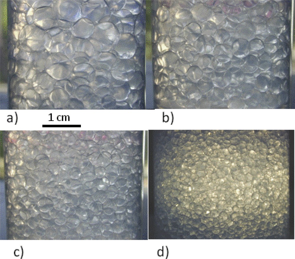
As just described, the size of oil droplets may be easily tuned by the amount of particles for Pickering emulsions. This brings the advantage of an independent control over the initial oil volume fraction and the drop size. The sol–gel process is equivalent to the one described earlier and the resulting materials are denoted as PHIPE for Pickering-based HIPEs. For example, keeping the oil volume fraction fixed, the drop size was varied and so did the resulting voids, ranging from 20 to 800 μm, a macrocellular void size domain never reached before (Fig. 12).
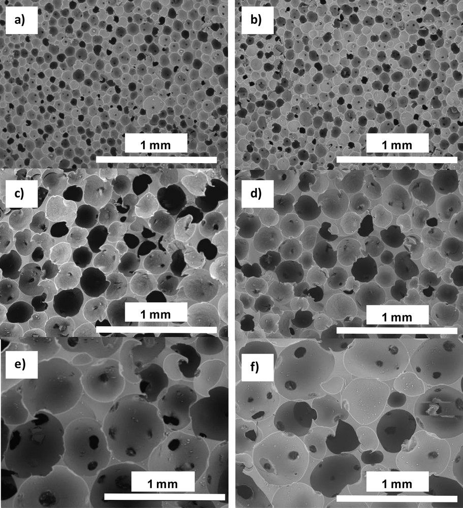
SEM images of solid foams synthesized from 64% PDMS-in-water emulsions: a) and b) 7.3Si(PHIPE)64P, c) and d) 3.7Si(PHIPE)64P, e) and f) 2.5Si(PHIPE)64P. Materials are observed either after drying (a, c and e) or after thermal treatment (b, d and f).Wiley Copyright 2012.
The Si(PHIPE) materials have been recently used as hard templates to generate the first series of carbonaceous foams “Carbon(PHIPE)” bearing very high monodispersity of the macroscopic voids while offering mesoporosity within the walls without the need for lyotropic mesophases [51].
4.2 Capsules from dilute Pickering emulsions
If the emulsions are dilute enough, no percolation can occur during the sol–gel process resulting in individual objects. Moreover it is possible to take benefit from the rigid and breakable nature of the drop surrounding the silica shell to produce a provoked rupture of it. This can be achieved through a mechanical stress or alternatively and more originally by a thermal stimulus. The strategy consists of replacing the fluid oil by a wax; fluid at temperature higher than the melting temperature Tm and solid at lower temperature [52–54]. The volume expansion induced by the wax melting is of the order of 10% and is enough to produce the mechanical stress responsible for the capsule rupture. The same strategy can be applied to produce capsules from simple direct emulsions referred to as wax@SiO2 core shell particles to account for their structure or to initial double emulsions either wax-in-water-in-oil [50] or to water-in-wax-in-water [51] emulsions. The advantage of such initial double emulsions is the synthesis of multicargo core shell particles allowing for the co-encapsulation of both hydrophilic and hydrophobic drugs, preserving the thermally provoked release.
4.2.1 Wax@SiO2 core shell particles
The proposed synthesis pathway [49] does not require the use of a sacrificial template to prepare monodisperse thermo-responsive capsules (Fig. 13).
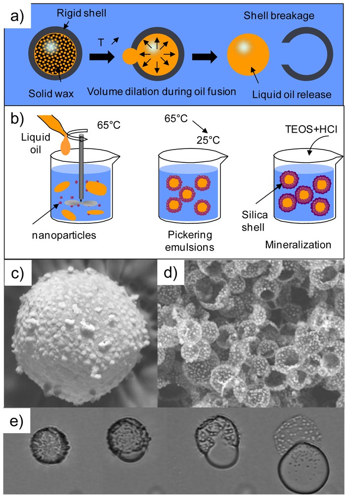
Thermo-sensitive simple capsules called Wax@SiO2 core shell particles combining Pickering emulsion and sol/gel chemistry. Schemes depicting a) the proposed concept and b) the elaboration principle. SEM images of the obtained capsules c) before and d) after the heating. The oil release is evidenced by empty capsules and by e) optical microscopy observation under heating. Copyright Elsevier 2014 [55].
First size-controlled Pickering emulsions are prepared at T > Tm exploiting the limited coalescence phenomenon described earlier. Then the emulsions are cooled down and the obtained suspensions are mineralized by the hydrolysis and condensation of TEOS at the wax–water interface, leading to the formation of capsules. Indeed as previously explained, mineralization preferentially occurs at the emulsion surface. The sizes of the resulting capsules are equal to the initial drop size showing no aggregation and formation of a shell around each individual drop. The shell rupture and the liquid oil release are provoked by heating above the wax melting temperature. Therefore this parameter can be tuned by the adequate choice of wax that can be of various origins: paraffinic, mineral or triglycerides. The resulting suspension can easily be dried into a powder beneficial for storage maintaining it sensitivity to temperature. As dispersion the rupturing scenario may be as the one reported in Fig. 13 that is to say a large crack in the capsule surface followed by the release of the capsule content at once. Alternatively, in the presence of a cationic or a non-ionic surfactant in the continuous water phase, the oil release can occur by the production of a multitude of very small droplets through small cracks in the shell, all the droplets exiting from the same crack being of the same size.
4.2.2 Wax@Water@SiO2 multicargo core shell particles
Complex multicore capsules maybe synthesized by combining the sol–gel process and formulation of wax-in-water-in-oil double emulsions (Scheme 5).
Schematic synthetic path for obtaining wax@water@SiO2 core-shell particles. Blue: water, dark orange: wax, orange: oil, white dots: silica nanoparticles [51] Copyright Wiley 2013.
The inner direct wax-in-water emulsion is stabilized with silica nanoparticles taking benefit from the limited coalescence phenomenon. In a second step, this obtained liquid dispersion is emulsified in poly-dimethylsiloxane (PDMS) using a non-ionic adapted surfactant to stabilize the second water/oil interface. A sol–gel process allows mineralizing the as-generated double emulsions giving rise to wax@water@SiO2 multicore capsules [50]. Due to the wax volume expansion through melting, these multicore capsules exhibit thermally stimulated release that is even enhanced when the surfactant is added in the surrounding continuous oil phase (Fig. 14).
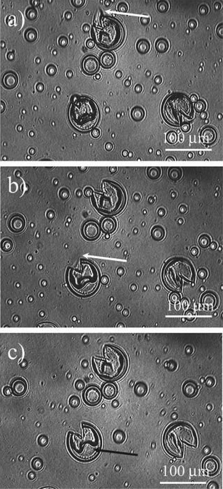
Optical microscopy images showing what happens when the temperature is raised above Tm. The white arrows indicate the wax which is expelled from the capsules and is dissolved in the surrounding PDMS. The black one points at the water droplet during its dewetting from the silica capsule [51]. Copyright Wiley 2013.
In addition, the melted wax release can be tuned from a one-step process to a more sequential dropping mode by varying the mineral precursor tetraethoxy-orthosilane (TEOS) concentration in the oily phase during mineralization.
4.2.3 Water@Wax@SiO2 multicargo core shell particles
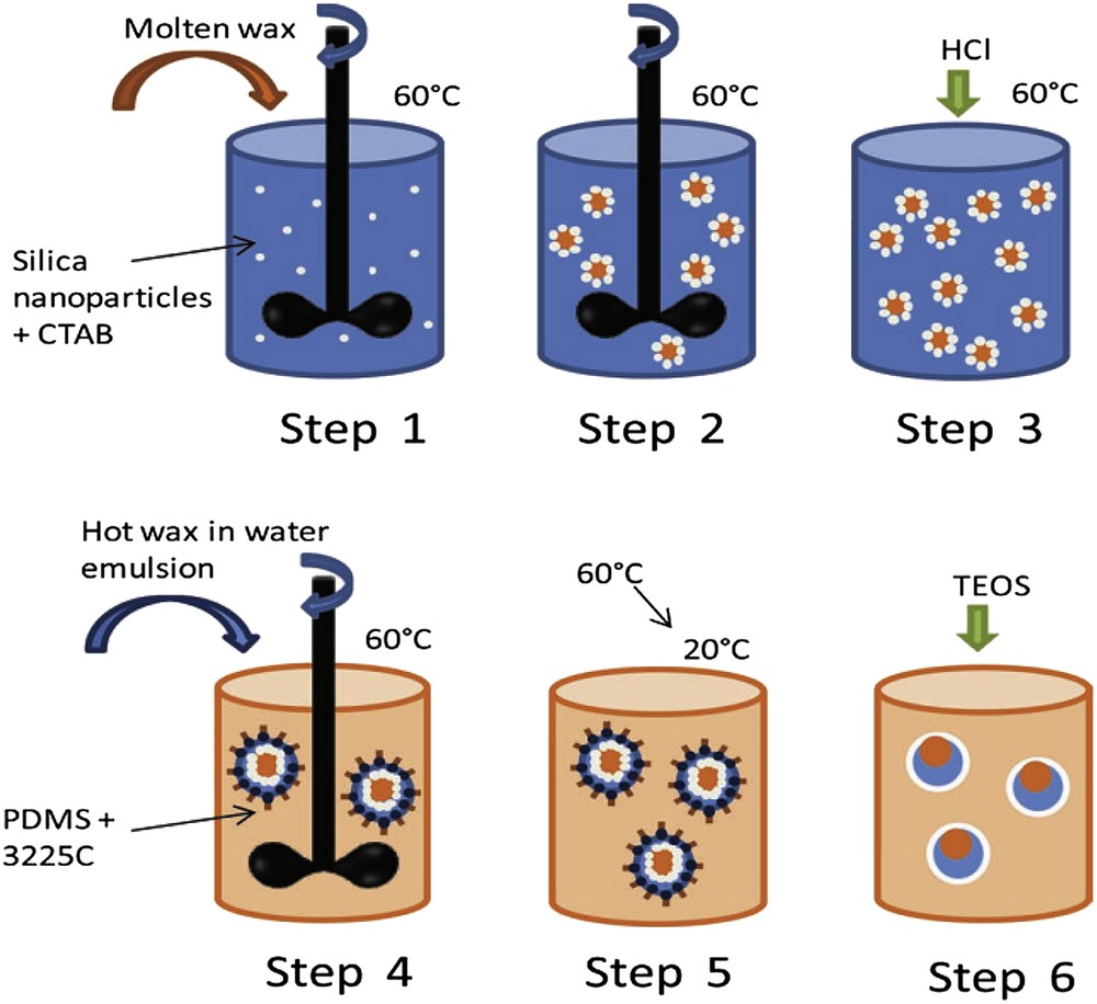
It can be of interest to deliver drugs in a water continuous phase. Then water-in-wax-in-water double emulsion can be the starting point to elaborate such complex multicore capsules by again combining the sol–gel process and Pickering emulsions [51]. The double emulsion is prepared at T > Tm in a two-step procedure. First a reverse water-in-melted oil emulsion is prepared in the presence of rather hydrophobic silica particles and then this emulsion is itself dispersed in water in the presence of more hydrophilic silica particles (double Pickering emulsion). Two opposite particle wettabilities are required to stabilize the two kinds of emulsions (reverse and direct). For both steps, the limited coalescence phenomenon can be operative giving a control over the drop size through the amount of stabilizer. As a result the obtained emulsions have well-defined and controlled drop sizes. After cooling at room temperature, the emulsions are mineralized through TEOS hydrolysis and condensation and capsules, made of a wax-in-water core, surrounded by a silica shell are obtained. The full synthetic path is described in Scheme 6. Hydrophilic rhodamine has been used to mimic a drug and to evidence the thermally induced release.
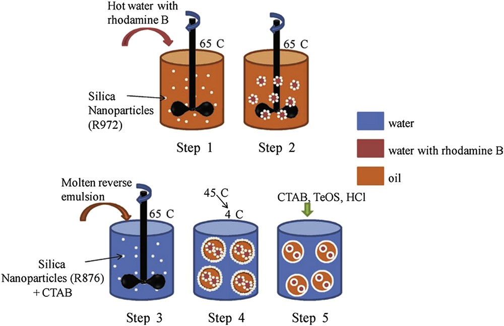
Schematic synthetic path for obtaining water@wax@SiO2 core-shell particles [51]. Copyright Wiley 2013.
The intermediate emulsions as well as the obtained capsules are visible in Fig. 15. Once again, in the dilute regime, mineralization preserves the drop individuality leading to well dispersed capsules. The use of wax as the intermediate phase confers the thermal sensitivity to the capsules.
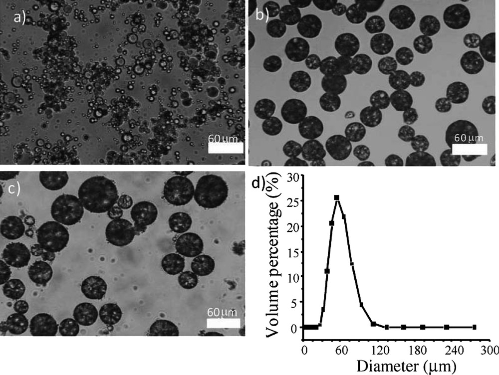
a) Optical microscopy of the starting simple reverse emulsion, b) optical microscopy of the water-in-wax double emulsion at ambient temperature, c) mineralized water-in-wax double emulsions, and d) Water@Wax@SiO2 particles sizes distribution [51]. Copyright Wiley 2013.
Owing to its absorbance spectrum, the location of rhodamine can be observed by confocal microscopy and its thermally stimulated release can easily be evidenced as reported in Fig. 16.
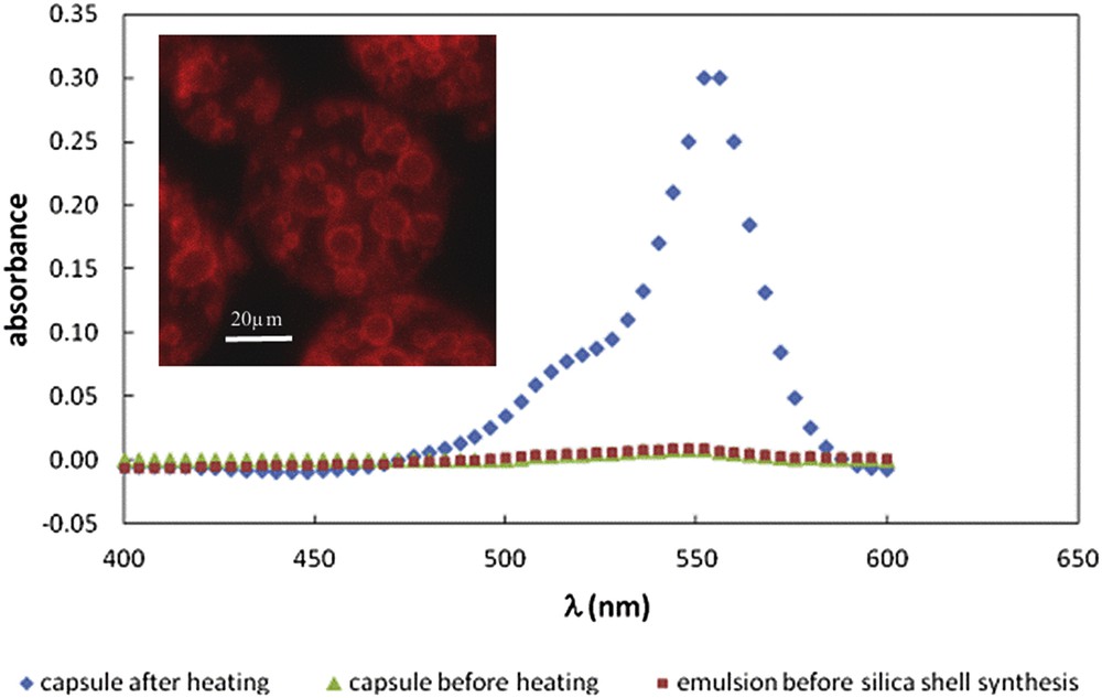
Determination of rhodamine B encapsulation by spectroscopic titration of the external aqueous phase. Inset: confocal microscopy image showing that before the release, there is no fluorescence in the outer aqueous phase, rhodamine B is hence totally located in the capsule and at the interfaces [51]. Copyright Wiley 2013.
5 Conclusion and perspectives
We have depicted correlations between emulsion-based porous materials and capsule rational design and applications thereof, where fluid complexes and sol–gel chemistry are combined. Nothing would be possible without operating chemical reactions at low temperature when addressing the “Chimie douce” synthetic path [56]. As mentioned in the introduction we are far from being exhaustive as for instance the design of fibers, 2D arrays are here omitted on purpose, but treated more or less exhaustively elsewhere [57]. Considering the emulsion-based capsule synthetic paths shown here, future work would take benefit of employing micro- or milli-fludics, in order not to play only with double or double emulsions but triple and why not quadruple emulsions while offering an outstanding monodispersity of the droplet diameters [58]. The second important issue is the use of hybrid organic-inorganic polyHIPE to create new porous materials bearing more complex active species closer to biology, namely prokaryotic and eukaryotic cells. Overall, these fields of research would ensure a promising future in materials science and high performances are expected in several domains like photonics, heterogeneous catalysis, photo-catalysis, hydrogen production and storage, carbon dioxide sequestration, differential drug delivery, filtration, energy conversion and so forth.
From a more academic point of view, and certainly more importantly, we still have to answer one question: beyond positioning chemical reactors within the geometric space, what is missing still to operate chemical reactions with the same complexity and specificity as mother Nature? One answer is based purely on chemistry while playing with molecular weak interactions offering either dynamical properties [1], breathing figures [59] or self-healing capabilities [60]. This first answer is certainly of importance, but not complete, as we are still always driven by the thermodynamic equilibrium. Then, it would be of first importance to consider chemical reactions “out of the thermodynamic equilibrium”, chemical reactions driven by kinetic/diffusion known as oscillating reactions [61], one of the most famous being the Belousov–Zhabotinsky reaction [62]. Considering these oscillating reactions, they offer the possibility of positioning chemical reactions within the temporal dimension. Now, by combining supramolecular and integrative chemistry with oscillating reactions, one will be able to address multiplex chemical reactions with a strong spatio-temporal control offering all possibilities of design and functionalities at both various time- and length-scales.