

1 Introduction
The development of nanostructured materials has been receiving increasing attention in recent years in various fields of applications and especially in catalysis and adsorption. Such materials include for example: zeolites, carbons, clays, MoS2, graphene, carbon nitrides, Layered Double Hydroxides (LDHs), Metal Organic Frameworks (MOFs), carbon nanotubes, mesostructured materials (carbons and oxides), hybrid materials, bioinspired materials, nanoparticles, etc. Yet, industrial needs are rather focused on optimizing properties of existing catalysts and adsorbents. These can be achieved by creating hierarchical porosity in micro- or mesoporous systems by controlling the macroporous network to improve heat and mass transfer which enhances the accessibility to the active sites and diffusion issues. These materials also allow for controlling the contact time, which is a key parameter for increasing selectivity and limiting the occurrence of secondary reaction. The macroscopic shaping has to be designed for the integration of the material in processes where the lifetime and the selectivity of the material will be improved. Moreover, economic and environmental issues push towards implementation of catalytic and separation processes in continuous flow mode, with the advantages associated with easier phase separation and product recovery, safety and easier operation. Consideration of cost and environmental impact (eco-design) has also become indispensable in new materials synthesis. Innovative synthetic strategies such as the creation of porosity on different length scales, microporous/mesoporous/macroporous (so-called hierarchical porous materials) [1], or the development of synthesis routes permitting the achievement of nanocrystals and their immobilization in shaped bodies adapted for their integration into processes are needed. For example, in the field of zeolites, several approaches can be followed to improve their efficiency. Mesopores can be introduced in the micron-sized crystals by dealumination/dessilication, by the association of nanocrystals or nanosheets of zeolites or by partial delamination of the zeolites followed by a different reconstruction [2,3]. Similarly, it is important to optimize the stability of the materials (for example, in zeolite synthesis, silanol defects should be avoided and the dispersion of heteroatoms (Al, Ti, Ge) has to be controlled) to increase their durability and enable a detailed understanding of their properties.
Most of the materials, which are active in catalysis and in adsorption, are produced in the form of micron-sized powders and are used as millimetric particles (extrudated) or washcoats (after grinding) on ceramic monoliths to be used industrially. The shaping expertise relies mostly on industrial knowledge while few academic groups have made research effort in formulations. The implementation of new material formulation methodologies must be accompanied by a scientific approach. For example, preparation of extrudates or washcoats can rarely be made without the use of binders (clays, silica, alumina, polymers,⋯) or additives. It is therefore necessary to understand the interactions between binders and additives with the active phase that can affect the properties of the materials, which can be quite different between the lab scale and the industrial use [4]. The design of catalytic bodies that do not rely on the use of binders is of prime importance.
Promising emerging materials, such as hybrid materials (MOFs, bioinspired materials, biocatalysts, etc.), can also help to solve some of the challenges in the areas of catalysis, adsorption and separation. If their extraordinary variability is a major asset, the challenge ahead lies in their shaping and improvement of their mechanical, chemical and hydrothermal stability. Similarly, process improvement can be achieved with well-known zeolites used on an industrial scale (FAU-Y, FAU-X, LTA, SAPO-34, ZSM-5, MOR, *BEA, TS-1) by improving secondary porosity and shaping. Other zeolite structures also appear increasingly important as partially delaminated zeolites (FER, MWW, MCM-22), the so-called 2D zeolites. Besides zeolites, other lamellar materials could also be optimized by shaping them as nanoparticles or by creating mesoporosity, as for example NiMoS2 for hydrotreatment catalysis or MoS2 to replace noble metals like Pt. The formulation of the catalysts and adsorbents is a key point for the improvement and intensification of existing processes.
The objective of our research in adsorbent and catalyst synthesis is to improve mass and heat transfer, to control the contact time between the reactants and the host material, and to increase mechanical and hydrothermal stability of materials. Each of these aspects contributes to the improvement of catalyst's lifetime and selectivity. For this purpose we have demonstrated that the rigorous control of shape into monolithic bodies with well-defined homogeneous hierarchical porosity brings novel and great potential to improve process efficiency in catalysis and adsorption. In this presentation, we will review the most efficient monolithic catalysts and adsorbents we have achieved [5–20] and some new opportunities.
2 Materials synthesis
2.1 Silica monolith synthesis
A very precise amount of tetraethylorthosilicate (TEOS, Aldrich) (20 g) is weighed and left at −19 °C for 1 h. In a 100 mL Erlenmeyer, water (24.560 g) is precisely weighed and then (2.313 g) nitric acid (68%) is added. The mixture is stirred for 5 min at room temperature. A precise amount (2.534 g) of polyethylene oxide (PEO) (20 kDa) is weighed, added to the mixture and stirred at room temperature until the polymer is completely dissolved. The mixture is left for 10 min at −19 °C in a freezer to cool down the solution without freezing. The flask is then placed in an ice bath well surrounded by ice and stirred. TEOS (coming from the freezer) is directly added to the slurry and the solution is stirred for 30 min. The final composition of the mixture in molar ratio is: 1 Si/0.60 EO/0.26 HNO3/14.21H2O. Eight polyvinyl chloride (PVC) tubes of 8 mm in diameter and 10 cm in length are closed on one side with a cap, sealed with parafilm and kept at −19 °C in the freezer. The tubes are taken from the freezer and filled with the mixture of the ice bath. The tubes are then closed by caps and sealed with parafilm and left in a 4 L water bath at 40 °C for 3 days. The phase separation and the sol–gel process take place, monoliths are formed resulting in 1 mm shrinkage around the section of the monolith. Monoliths are then removed from the tube molds and placed in a 1 L water bath at room temperature. Water is changed every 30 minutes until reaching a neutral pH (around 5 washing). The monoliths are then immersed in 1 L of aqueous ammonia (0.1 M) in a polypropylene bottle and left in an oven at 40 °C for 1 day. The resulting monoliths are placed in a water bath and water is changed every 30 min until neutral pH (around 3 washing). The monoliths are then dried at room temperature for 4 days and calcined at 550 °C for 8 h under air to remove remaining PEO.
2.2 Pseudomorphic transformation of silica skeleton into MCM-41
Silica monoliths obtained after the phase separation and sol–gel process (first step in acidic medium) are taken from the neutral water bath and reacted in an alkaline solution containing water, NaOH (Aldrich) and cetyltrimethylammonium bromide (CTAB, Aldrich). In a typical synthesis, two wet monoliths (2 × 10 cm, corresponding to 0.80 g each of dried and calcined SiO2) are taken and placed at the bottom of an autoclave. An aqueous solution is prepared by dissolving 0.213 or 0.107 g of NaOH in 192 g of water (for MCM-41 with a unique pore size at 3.5 nm and for MCM-41 with a double pore size at 3.5 and 10 nm, respectively). Then, 5.831 g of CTAB are added and the mixture is stirred for 1 h at room temperature. The alkaline solution is poured into the autoclave containing the monoliths and left in an oven at 115 °C for 6 days. The final composition in molar ratio is: 1 Si/0.60 CTAB/ x NaOH/400H2O (x = 0.2 or 0.1). Monoliths are then removed from the autoclave and placed in a 1 L water bath at room temperature. Water is changed every 30 minutes until reaching a neutral pH (around 3 washing). Monoliths are then dried at 80 °C for 1 day and calcined at 550 °C for 8 h under air to remove CTAB and remaining PEO.
2.3 Pseudomorphic transformation of silica skeleton into nanocrystals of LTA
First a seeding gel is prepared. 0.46 g of NaOH is dissolved in 47.46 g of water. 3.9 g of tetrapropylammonium hydroxide (TPAOH 20 wt%) is added, and the mixture is stirred for 10 min at room temperature. Then the magnetic stirring bar is removed and the mixture is stirred vigorously at 1000 rpm. 5.3 g of aerosil is added gradually and the agitation is kept for 1 h. Then, the solution is put into an autoclave and aged at 100 °C for 16 h. The obtained solution is kept at 4 °C.
A calcined silica monolith (5 cm, 400 mg) is placed at the bottom of an autoclave. 0.037 g of NaOH and 1.389 g of sodium aluminate (NaAlO2) are dissolved in 3.828 g of water. 0.251 g of seeding-gel is then added and the mixture is stirred until dissolution of the gel. Monolith is totally impregnated with the solution and the autoclave is closed and placed in the oven at 40 °C for 20 h and then at 70 °C for 24 h. Monolith is then recovered and put in a water bath at room temperature. Water is changed every 30 min until reaching a neutral pH (around 5 washing). Monolith is then dried at 80 °C for 1 day and calcined at 550 °C for 8 h under air.
2.4 Carbon coating of silica monolith and carbon replica
To synthesize coated-carbon silica monoliths and carbon monoliths, silica monoliths are first grafted with (3-aminopropyl)triethoxysilane (APTES). Silica monolith (5 cm, 0.400 g) is degassed under vacuum at 150 °C for 4 h. In a flask, 460 μL of APTES (excess of 5 molecules per nm2 of silica) is stirred in 50 mL of absolute ethanol. Monolith is immersed in the solution and let under reflux at 80 °C overnight. Monoliths are then recovered, washed with 50 mL of ethanol and dried at 80 °C for 24 h. 100 mg of NH2-monolith are used to graft sucrose. 2.30 or 6.75 mg of sucrose are dissolved in 20 mL of water for carbon-silica coated monolith and carbon monolith, respectively. The solution is put in a Schlenk tube and the NH2-monolith is immersed and set under vacuum at room temperature to force the sugar solution to penetrate into the porosity of the monolith. The monolith and the solution are then put in an autoclave at 110 °C for 5 h and then at 180 °C for 15 h to insure sugar polymerization. The resulting brown polymer-monolith is removed, washed with water several times and with ethanol and dried overnight at room temperature. To obtain a carbon/silica-monolith, the monolith is pyrolyzed at 950 °C under nitrogen. To obtain a carbon monolith, the silica skeleton is removed by immersing the monolith in 10 mL solution of hydrofluoric acid (3% molar in ethanol) for 24 h. The monolith is then washed two times with 20 mL of ethanol for 24 h.
2.5 In-situ synthesis of NiMoS2 nanoparticles into silica monoliths
A calcined silica monolith (6 mm diameter, 1 cm length) was impregnated with 100 mL of an aqueous solution of (NH4)2MoS4 (0.1 M) for 1 h under stirring and dried for 1 h at room temperature and then for 1 h at 50 °C. The impregnation and drying process was performed 3 times followed by drying overnight at 50 °C. The monolith was then impregnated with 100 mL of an aqueous solution of Ni(NO3)2 (0.1 M) under the same conditions of impregnation and drying than for (NH4)2MoS4. The monolith becomes instantly black and after drying the entire section of the monolith becomes dark grey. The monolith is then washed 3 times with 30 mL of water for 10 min, left overnight in ethanol, washed 3 times with ethanol for 10 min and dried in an oven at 50 °C. The dried monolith is then calcined at 500 °C (1 °C/min) for 2 h under Ar.
2.6 Cladding of monoliths
To generate a microreactor, the monoliths (6 mm diameter, 10 cm length) are cut to the desired length and inserted in a heat-shrinkable PTFE polytetrafluoroethylene (PTFE, DSG-CANUSA) tube together with two glass tubes (4 mm inner diameter) at each end and heated at 350 °C for 5 min.
2.7 TiO2 monoliths and photocatalysis test
Titanium (IV) n-propoxide (Ti(OPr)4), polyethylene glycol (PEO, Mw 10 kDa), ethyl acetylacetonate (EtAcAc), ammonium nitrate (NH4NO3) and 1-propanol (PrOH) were purchased from Sigma–Aldrich. All reagents were used as received. Distilled water was used in all experiments. In the synthesis 14 mL of PrOH and 10 mL of EtAcAc were added to 20 mL of Ti(OPr)4 and mixed in a flask. When a homogeneous solution was obtained, 1.75 mg of PEO were added and the temperature was increased to 60 °C in the water bath. After complete dissolution of PEO, temperature was brought down to 40 °C and 4 mL of a 1M NH4NO3 aqueous solution was slowly added under vigorous stirring. After stirring for 3 min, the homogeneous solution obtained was transferred into PVC tubes of 8 mm diameter and 10 cm length closed with caps and sealed with parafilm, and the tubes were allowed to stand at 40 °C for 24 h. The resulting wet monoliths underwent a solvent exchange process in a closed container at 60 °C in the following solutions of EtOH/H2O (v/v): 1/0 (72 h), 9/1 (24 h), 7/3 (24 h), 1/1 (24 h), and 3/7 (24 h). The monoliths were then dried at 40 °C for 72 h and calcined at 350 °C for 5 h with a rate of rising temperature of 0.5 °C/min.
The disappearance of a dye, named Orange-G (purchased from Sigma-Aldrich), was performed adding TiO2 monoliths to the dye solution. A piece (100 mg, 1 cm) of monolith was immersed in 10 mL of 80 mg L−1 solution of Orange-G in a polyethylene container sealed with parafilm and let in static for 5 h. Different experiments were performed: a sample was kept in aluminum paper in order to avoid light exposition, a second was exposed to sunlight and a third sample was exposed to a UV lamp (125-W Hg lamp, from UVP). The UV–Vis spectra of the resulting solutions were recorded in the wavelength range 280–600 nm using a PerkinElmer Lambda 35 after diluting ¼ with distilled water. Concentrations of dye have been determined by integrating the peaks from 300 to 500 nm.
3 Results and discussions
3.1 Best criteria for optimal mass transfer within materials
To define the optimal parameters of a catalyst or an adsorbent for the highest mass transfer, the Van Deemter equation (H = A + B/u + Cu) (Fig. 1) [21,22] was employed, which distinguishes mass transfer in the macroporous network (A parameter) and in the mesoporous network (C parameter) in a bed of porous particles. This equation is usually applied in chromatography [5–7,23–25] and relies on the concept of plate height H being proportional to the peak width (Eq. (1)) of a solute with the linear velocity u (proportional to flow rate D) in continuous processes. Plate height will depend on column packing (hydrodynamics, dead volume), particle size scattering and linear velocity.
| (1) |
| (2) |
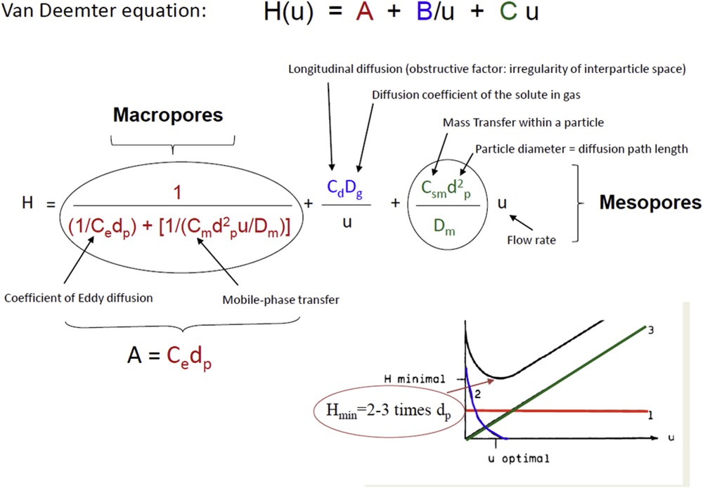
Numerical and graphical representation of the Van Deemter equation correlating plate height with linear velocity: A term represents the mass transfer in the macropore network and is independent of flow rate, B term is the lateral diffusion of the solute in the liquid (mainly dependant of the solute) mainly contributing to a larger peak at low flow rate, C term represents the mass transfer in the mesoporous network and contributes to a larger peak at larger flow rate. An optimal flow rate is therefore obtained for a minimal plate height usually found at 2–3 times the particle diameter.
The parameters A and C of the Van Deemter equation have to be minimized to improve mass transfer at both porosity scales. The Van Deemter equation teaches that mass transfer in macropores is improved for columns packed with small particles, homogeneous spherical particles and homogeneous distribution of the macropore size. As far as mass transfer in the mesoporous network is concerned, the particle size is even more crucial as it contributes with a square exponent in the equation. An efficient mass transfer will be achieved for small diffusion path lengths. The C parameter of the Van Deemter equation is also inversely proportional to the diffusion inside particles (i.e. internal diffusion). Thus, the diffusion rate has to be as large as possible. To illustrate the relationship between diffusion and mesopore size, we have used an empirical equation proposed by Renkin [26] (Eq. (3)) where the diffusion in a porous medium is described using the concept of tortuosity and a parameter λ, which is the ratio of the diameter of the diffusing molecules and the pore diameter (the inverse is also called, reduced pore size).
| (3) |
The tortuosity τ is defined as L/L0 where L is the average path length in the porous material and L0 is the path length in the absence of the solid. While several definitions are possible for τ, this definition is consistent with NMR experiments in which τ is the diffusion formation factor. To analyze the effect of tortuosity on mass transfer, we have performed chromatographic experiments to determine the C parameters from Van Deemter curves (Fig. 2). Both MCM-41 (straight pores) and MCM-48 (interconnected porosity of gyroid type) materials with spherical particles of same size (10 microns) were considered. These two materials were prepared by pseudomorphic transformation [5,27–35] of the same initial silica spherical beads using the same surfactant (leading to the same pore diameter) so that they differ only through their tortuosity. Considering Eq. (3), whereas the tortuosity in MCM-48 is higher than in MCM-41, the diffusion in MCM-48 was higher than in MCM-41. This can be explained by the fact that a packed-bed consists of thousands of particles and not only one. For MCM-41, if particles have their straight porosity perpendicular to the flow the diffusion within the particles will be limited. It is therefore more efficient to have an interconnected porous network than independent pores in order to improve diffusion inside of each particle making-up the packed bed. In these chromatographic experiments [5], we have also shown that improved diffusion rate (smaller C parameter) is obtained for homogeneous pores (no constriction) and larger pores. All the materials with different pore sizes were prepared by pseudomorphic transformation of the same initial silica particles (10 microns) with dibutylphtalate (diameter 1.3 nm) as the solute.

Evolution of C parameter of the Van Deemter equation as a function of pore size for chromatographic measurements performed with packed-bed columns filled with 10 micron particles of a commercial silica LiChrospher 60 (Merck) and of its pseudomorphs in MCM-41, MCM-48, and MCM-41 swelled with trimethylbenzene (MTS-TMB) and with a mixture of TMB and decane (leading to mesopores with constriction). Solute: dibutylphtalate. Figure adapted from ref. [5].
By plotting the polynomial function f(λ) of Eq. (3) as a function of reduced pore diameter 1/λ (Fig. S1), we found that diffusion increases continuously with pore diameter. This result is indeed straightforward, larger pores allow higher diffusion rates. However in catalysis or in adsorption, it is furthermore necessary that the molecules enter in contact with the surface of the pores where the active phase is detained. This implies that maximum interaction will be achieved in an opposite direction, namely for very small pores generating materials with large surface area. There is therefore a compromise to find between diffusion and reactivity. To illustrate this compromise, the Ruckenstein equation (Eq. (4)) [36] has been used and transformed using different theories (Giddings, Peterson, Renkin) to express the reactivity of a catalyst as a function of the reduced pore size (1/λ) (Fig. S2).
Such an expression, which has been plotted in Fig. 3, shows that the maximum rate of a catalytic reaction is obtained for a material featuring a pore diameter equivalent to 5–7 times the size of the reacting molecules. Interestingly, the ratio of 7 between the pore diameter (cylindrical pore of radius R0 and length L) and the molecule size (spherical shape) corresponds geometrically to pores for which there is the same amount of molecules interacting with the surface and molecules inside the core volume of the pore. For smaller pore diameters, the reactivity decreases rapidly so that it is preferable to have larger pores rather than small pores to ensure the best compromise between reactivity and diffusion. To calculate the optimized pore diameter, the larger molecules involved in the catalytic or transport process should be considered. For molecules with a kinetic diameter standing between 0.5 and 1 nm, the optimized catalysts or adsorbents should have a pore diameter between 3.5 and 7 nm, respectively.
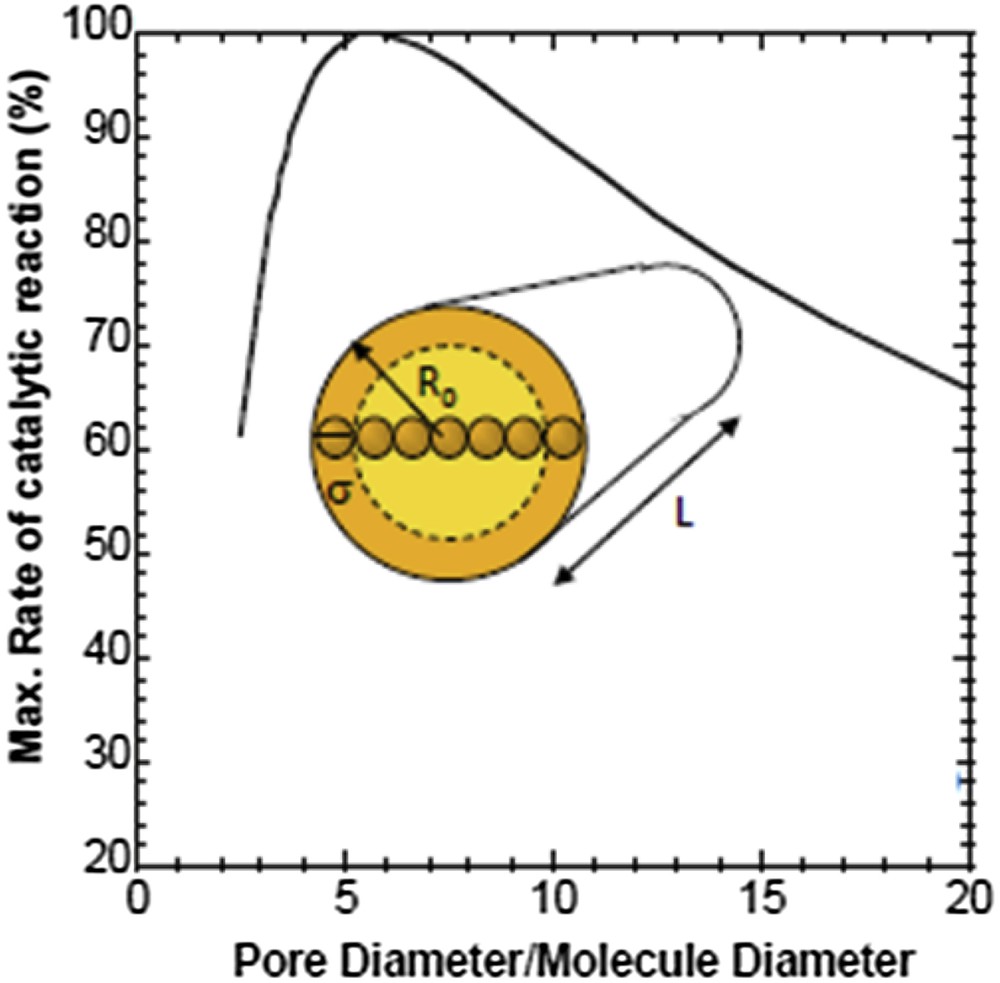
Graphical representation of the Ruckenstein equation representing the rate of the catalytic reaction as a function of reduced pore (pore diameter of radius R0 divided by the molecule diameter σ).
The equations above allowed us to define the best characteristics for a catalyst or adsorbent used as a packed-bed in a continuous flow process. As far as the macroporous network is concerned, the material should be shaped as spherical particles and the particle size distribution should be narrow and the size as small as possible. Moreover, the resulting macroporous volume should be high and distributed homogeneously. For the mesoporous network, the diffusion path length (i.e. particle size) should be very small, the pore diameter should be adjustable depending on the considered molecules (pore diameter 7 times the size of the largest molecules of the reaction), the surface area and the mesoporous volume should be large, the pores should be homogeneously distributed in size and interconnected in the particle.
Spherical particles with sizes in the range of microns lead to a homogeneous macroporous network in adsorbent or catalytic beds with a large macropore volume (∼1 mL g−1) as revealed by mercury porosimetry (Fig. 4), where, after compaction of the beads (slight slope at larger pore diameters) mercury penetrates into the macropores (i.e. space in between the particles) with a sharp step. The position of this step gives the macropore size in the packed-bed, which is dependent on the particle size. The macropore diameter is 0.38 times the size of the particles. Yet, decreasing the particle size to optimize mass transfer will decrease the macropore size and increase drastically the pressure drop (ΔP) by decreasing the permeability of the column as expressed in Darcy's law (Eq. (5)): u is the linear velocity.

Mercury porosimetry of commercial silicas: Nucleosil 100-5 (Macherey–Nagel), LiChrospher 60 (Merck), Davicat 1700 (Grace-Davison) featuring 5, 12 and 50 micron particle size. Relationship between macropore diameter and particle diameter.
As an example, packed beds of spherical particles of 7, 4 and 3 microns in diameter will develop a pressure drop (ΔP/L) of 7, 20 and 35 bar cm−1, respectively, for a linear velocity u of 0.2 cm s−1 (Fig. S3)[37]. Dividing the particle size by 2 increases the pressure drop by a factor higher than 5. For columns of 4 cm, the pressure drop will be very high (30–140 bar), which is usual for chromatographic measurements but not acceptable in catalysis or in adsorption where small pressure drops are required. Usually, particle sizes larger than 60 microns are used in catalysis or adsorption processes to minimize pressure drops. To overcome this low permeability issue with small particles, novel materials have been developed leading to hierarchical meso/macroporous monoliths [38] with macropore diameter of similar or larger size than their skeleton thickness as shown in Fig. 5 (in contrast to spherical particles where the macropores are equal to ∼1/3 the particle size). The permeability of these monoliths is much larger than that of packed bed filled with particles with the same size of the skeleton thickness. Indeed, the permeability will depend on pore volume, pore connectivity, pore size, but also on the homogeneity of the pores distribution. With monolithic materials, for the same mesoporous path length (particle size or skeleton thickness), the macropores will be larger and very homogeneous as no throat-pores exist (as is the case between particles). The stagnation layer at the surface of the macropore will be of constant thickness, which is not the case for a packed bed with contact points in between particles creating stagnation zones of a larger thickness. Diffusion through the stagnation layer to enter the mesoporosity is expected to be equivalent in all volume of the monolith, leading to a higher control of the contact time. The great homogeneity of macropore sizes in monoliths is evidenced by mercury porosimetry with a sharp step in mercury intrusion in the micrometer size (Fig. 6). These monoliths with hierarchical meso-/macroporosity feature a high macropore volume of 1.5–2 mL g−1 and are very stable as shown by the two reversible cycles in mercury intrusion performed until 4000 bar. The synthesis of this new kind of monoliths has been disclosed by the group of Nakanishi in 1992 [38] and is performed by a two-step synthesis (Fig. 7). First, a phase separation initiated in acidic medium occurs between silica coated with polymer (polyethylene oxide – PEO) and water. During this process the silica precursors present undergo sol–gel transition and suspended the uniform phase separation, named spinodal decomposition. This step allows the formation of the macroporous network of the monolith with a poorly condensed silica skeleton. One of the influencing parameters is the molecular weight of PEO, which allows to control the size of the macropores from 2 to 20 microns for PEO from 10 to 100 kDa. Second, an alkaline treatment is additionally performed by either an impregnation of the monoliths in an ammonia bath or by heating the monolith at 120 °C when urea is used during the synthesis in order to produce in-situ ammonia. This step allows to condense silica into small particles through Ostwald ripening, and allows controlling the mesopore size from 6 to 30 nm by increasing the temperature of ammonia bath from 40 to 150 °C with a concomitant decrease in the surface area from 800 to 100 m2 g−1 [5,6]. Similar increases in mesoporosity from 6 to 35 nm can be reached by increasing the duration of the thermal treatment at 120 °C with urea from 3 to 48 h at a urea/Si ratio of 0.5. For mesopore sizes between 2 and 11 nm, it was possible to maintain a high surface area of 700 m2 g−1 by using different times of ammonia treatment at 40 °C (Fig. S4 and S5).
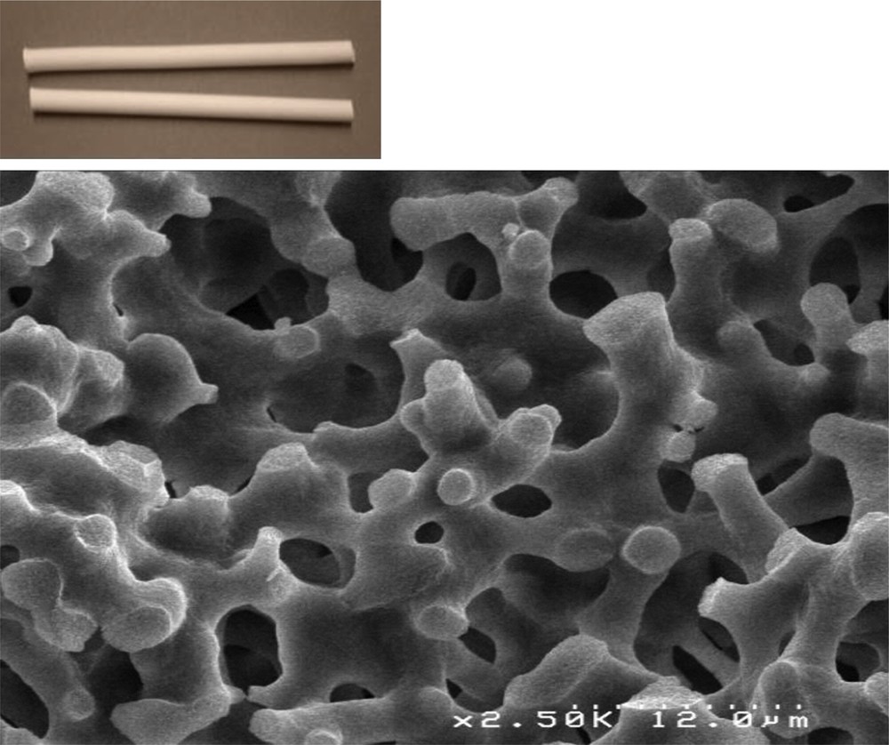
SEM picture and photograph of a monolith (6 mm in diameter and 10 cm in length) with macropores of 5 microns.

Mercury porosimetry of a monolith with macropores of 5 microns and mesopores 10 nm in diameter. Two cycles of intrusion (until 4000 bar) and extrusion have been performed.

Schematic representation of monolith synthesis.
The monoliths with the smallest macropore size (2 microns) and skeleton thickness have been employed successfully in chromatography [5,6,39] and commercialized since the 2000's by Merck under the name of Chromolith™. The hierarchical porous monoliths of 2 microns of macropores and a skeleton thickness of 2 microns featured the same efficiency (plate height, Hmin = 11 microns) as a packed bed of 3-micron particles, but with a pressure drop of 2 bar cm−1 instead of 35 bar cm−1 [37], and are therefore able to be operated at much higher flow rates in comparison to packed bed for ultrafast chromatography. Some extraordinary improvements have been obtained in chromatography with a second generation of monoliths with smaller macropores of 1.2 micron and 1.6 micron skeleton thickness, leading to very thin symmetrical peaks (plate height, Hmin = 6.7 microns) even at high flow rates (4 mm s−1) [23,24]. However the pressure drop was increased by a factor of 3 (6 bar cm−1) and these kinds of monoliths are not suited to be used in catalysis or adsorption experiments as no pressure drop (or less than 1 bar cm−1) is tolerated.
To test the efficiency of this object featuring exceptional mass transfer in catalysis and adsorption, we have developed a synthesis of hierarchical monoliths with a macropore size of 5 microns and a skeleton thickness of 3 microns (Fig. 5). These silica monoliths feature all the requirements for the optimal mass transfer in macropores and in mesopores and a weak pressure drop of 0.02 bar cm−1. Most of the monoliths described in the following sections have been tested as bodies of 6 mm of diameter and 2–5 cm of length with a surface area of 700 m2 g−1, a mesopore diameter of 10 nm, a mesopore volume of 1.2 mL g−1, a macropore size of 5 microns, a skeleton thickness of 3 microns and a macroporous volume of 1.5 mL g−1. To ensure continuous flow mode, monoliths were cladded with a heat shrinkable Teflon clad and ended by two glass tubes to adapt the (swagelok) connections to the circulating pump.
3.2 Hierarchical monoliths with homogeneous porosity in catalysis
Silica monoliths have been functionalized by different procedures to create active catalytic sites (Fig. 8) on the surface for various catalytic reactions (Fig. 9). Amino silanes and sulfonic silanes have been grafted in flow on silica monoliths to perform basic and acidic reactions, respectively [9]. The sulfonic acid-monolith was evaluated in a model reaction of transesterification of triacetine by methanol to mimic the reaction of transesterification of triglycerides to produce biodiesel. The basic amino-monolith was tested in the Knoevenagel condensation (Fig. 9), an important reaction to produce pharmaceuticals as the antimalaria drug lumefandrine or coumarin. Further, the silica monolith was grafted with alumina and the Diels–Alder reaction was performed in flow [12,14]. This is an important reaction to produce pharmaceutics as the stereoselective synthesis of morphine. The Metal-Organic Framework (MOF) CuBTC has been synthesized in-situ within the mesopores of the monolith in the form of nanoparticles to perform catalysis with copper in a very specific environment [16]. This CuBTC-monolith was used in the preparation of N-heterocycles; a very useful approach for the synthesis of numerous pharmaceutics. Pd nanoparticles were synthesized in-situ in the mesoporosity of the monolith to perform selective hydrogenation reactions [18,19] as for example the production of the fragrance cis-hexene-1-ol with the smell of leaf alcohol (which amounts a production of 400 tons per year in batch employing the Lindlar catalyst consisting of Pd doped with toxic Pb and supported on CaCO3). The skeleton of the silica monolith was moreover transformed by pseudomorphic synthesis into zeolite phases (SOD, LTA) and exchanged with potassium to perform basic catalysis as the Knoevenagel reaction presented above [11,12]. All results and descriptions of the functionalization techniques and catalytic tests can be found in the corresponding publications.

Schematic representation of the versatile functionalization of the monoliths.
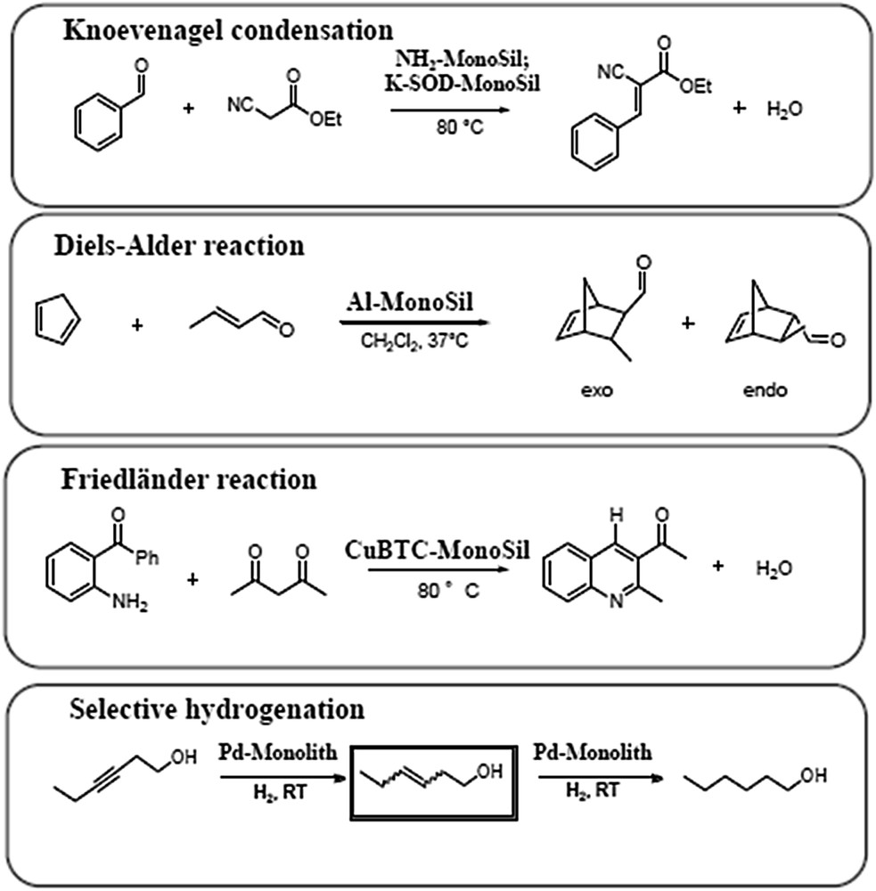
Representation of the different catalytic reactions performed with the monoliths of Fig. 8.
By analyzing the catalytic results some important features were disclosed. Firstly the appropriate size (length) of the monolith has to be identified in order to avoid external diffusion limitations. As an example, the Diels–Alder reaction was studied with monoliths of 6 mm diameter and 1, 2, 3, and 4 cm length at increasing flow rates (0.01, 0.02, 0.03, 0.04 mL min−1) to assure constant contact time [14]. For a contact time of 16 min, the conversion increases when increasing the flow rate and stabilized for flow rates above 0.03 mL min−1 (Fig. 10). This means that below 0.03 mL min−1 external diffusion limitation prevails and that under the conditions of our test, flow rates above 0.03 mL min−1 are required to pass the stagnation layer present at the surface of the macropores. This is a nice example that illustrates how these fascinating materials can be used in a very simple manner to elucidate mass transfer issues. For this reaction, the ratio of monolith diameter to monolith length should be 1:5 or 1:7 or above. Classically, in the catalysis industry, the ratio used between bed diameter and bed length (height) for the packed-bed reactor is in the range between 1:3 and 1:5. For our monoliths of 6 mm diameter, it is therefore better to first test the reaction with monoliths of 3 or 4 cm length and then optimize the contact time and the flow rate to increase the productivity (also called space-time yield when expressed as the number of molecules produced per bed volume and per hour). For the Diels–Alder reaction with a monolith of 4 cm length, the flow rate was increased and the contact time decreased to reach a maximum productivity at 0.07 mL min−1 corresponding to a contact time of 10 min (Fig. S6) [14].

Conversion as a function of flow rate for the Diels–Alder reaction performed with alumina grafted silica monolith with different lengths to keep the contact time constant (adapted from ref. [14]). Schematic representation of the external diffusion limitation due to the stagnation layer present at the surface of the skeleton.
A second important feature is the exceptionally larger efficiency and productivity obtained with the monolith in comparison to packed-bed and batch reactors, both using the same monolith but crushed into particles of 60 microns (Fig. 11). The same monolith mass was used for the 3 experiments. A size of 60 microns for particles has been chosen to lead to a similar pressure drop as the monolith in the packed-bed column. For all the catalytic reactions presented above (Fig. 9) we noticed a constant and stable conversion with the monoliths, which was higher than the conversion obtained with the same monolith crushed into particles and used as the packed bed. This larger conversion can be explained by the continuous homogeneous macroporous network in the monolith featuring a uniform stagnation layer at the surface of the macropore and leading to a homogeneous distribution of contact time. The contact time in a packed-bed column filled with the same mass of monolith will be higher as the contact time is the ratio between the total pore volume and the flow rate; in a packed bed, an additional macroporous volume is present (around 1 mL/g as shown in Fig. 4) in between the particles. However, even if the contact time is higher (and should give a higher conversion), the existence of junctions in between particles lead to throat-pores creating locally thicker stagnation zones more difficult to pass by the molecules. Furthermore, an additional stagnation layer around the particles of 60 microns is also formed. These two supplementary barriers encountered for mass-transfer limitations as evidenced by the decrease in conversions. This supplementary macroporosity in a packed bed will add another A term in the Van Deemter equation: H = A1 + A2 + B/u + C u, where A1 is the mass transfer in the macropore network of the monolith and A2 the mass transfer in the macropore network in between particles of 60 microns. This will contribute to a larger dispersion of contact time. In terms of productivity or space-time yields, monoliths were at least twice more productive in comparison to packed-bed reactors and 3 times more productive compared to batches for all tested catalytic reactions.

Conversion as a function of time for the Knoevenagel reaction for a monolith grafted with propylaminosilane and for a packed bed made of the same crushed monolith (particle size: 60 microns). Comparison of productivity between the monolith and the packed bed and batch reactors made of the same crushed monolith (adapted from ref. [9]).
For the selective hydrogenation of hexynol (Fig. 12), monoliths proved to be very promising by mixing gas (H2) and liquid feeds and a productivity higher than 4 times the one obtained with the packed bed was found [18,19]. A comparison was done between a packed bed filled with crushed monolith and a packed bed filled with a xerogel featuring no internal macropores. A lower productivity (twice less) was found with the xerogel packed bed, revealing the relevance of hierarchical porosity macro/mesopores in particles even for packed-bed experiments. The conversion and selectivity obtained with monoliths (loaded with 1.3 wt% Pd) in selective hydrogenation were stable over time (80% conversion; 80% selectivity in hexenol) (Fig. 12) and lead to a productivity 10 times higher than that attained in batch experiments performed with the industrial Lindlar catalyst Pb, Pd@CaCO3. However the Lindlar catalyst was more selective (89% selectivity in cis-hexenol) than the monolith (80% cis-selectivity) because Pd nanoparticles were used without any additive as Pb. Some preliminary tests with some additional metallic promotors (metal/Pd = 1/3) as Pb, Ag (commonly used in industry for selective hydrogenation) and Cu (very effective at lab scale [40]) were performed but no increase in selectivity was noticed (Fig. S7). The very large productivity obtained with monoliths for selective hydrogenation is very promising, and improvements remain to be done in order to increase selectivity. One can imagine optimizing Pd nanoparticle distribution or using bimetallic nanoparticles starting from hydrogen silsesquioxane monoliths [41–43] and other supports as Al2O3 [15] or TiO2 [18] monoliths.

Conversion and selectivity as a function of time for the selective hydrogenation of hexynol with a monolith containing nanoparticles of Pd (adapted from ref. [19]). Comparison of space-time yield (productivity) between a monolith, a packed bed filled with crushed monolith, a packed bed filled with a xerogel (mesoporous sol–gel without macroporosity) and a batch reactor using crushed monolith (adapted from ref. [18]).
Other groups have started using this novel class of microreactors for catalysis [40–44] and exceptional results have been obtained in biocatalysis by grafting an enzyme (invertase) onto the monolith. This enzyme was used to transform sucrose into glucose and fructose [44]. A reactivity 1000 times higher than that of the native enzyme (or the same enzyme immobilized in crushed monolith performed in batch) was obtained. The exceptional mass transfer properties of these monoliths, leading to a fine control of the contact time, open the route to increased productivities in a wide range of catalytic reactions.
3.3 Hierarchical monoliths with homogeneous porosity in adsorption
3.3.1 Hierarchical monoliths for denitrogenation of fuels
Other applications such as the removal of pollutants have been investigated using hierarchical monoliths. Fuels (diesel and gasoline) enclose impurities such as sulfur and nitrogen-containing aromatic molecules, responsible for toxic gas emissions such as SOx, H2S, and NOx from motor vehicles. The development of highly active catalysts and processes for hydrotreatment is a major issue for refiners to reduce atmospheric pollution. In particular, the environmental legislation is becoming more drastic about sulfur content in fuels. Powerful hydrodesulfurization treatments exist but efficient catalysts (based on MoS2 promoted with Ni or Co – NiMoS2 or CoMoS2 and deposit on alumina) are deactivated by the presence of nitrogen-containing aromatic compounds. It is therefore necessary to remove these nitrogen impurities before hydrotreatment. This could be done in batch using ionic liquids to trap the nitrogen aromatics. However, after some time, the purification of ionic liquids is necessary through distillation, which is energy consuming. To avoid this costly step, an ionic liquid (BMIM TFSI) was supported on monoliths and a model fuel composed of heptane/toluene (4/1 v/v) containing various types of aromatic sulfur compounds (benzothiophene, dibenzothiophene) and aromatic nitrogen compounds (indole, dimethylindole, N-methylcarbazole) was flown through the monolith [20]. Breakthrough curves were obtained, showing that indole was selectively retained in the monolith while it was not retained on a packed bed made of commercial silica of 60 micron particle size featuring the same mesopore size. Adding copper to the ionic liquid allows one to selectively retain indole in the packed bed of silica and all the nitrogen compounds in the monolith. The homogeneous macropore network of the monolith allows a better accessibility to the active sites and a higher performance allowing a selective denitrogenation of the fuel feed. Adding iron to the ionic liquid supported on the monolith allows retaining selectively indole and dimethylindole (Fig. 13), leading to a model oil containing merely 33% of its initial nitrogen compounds. The monolith column can be then regenerated by flowing pure heptane to recover the adsorbed nitrogen compounds before performing other denitrogenation cycles with the same efficiency. Even in adsorption applications, monoliths have proven therefore to be more efficient than packed-bed reactors.

Breakthrough curves of nitrogen aromatic impurity removal from synthetic fuels with a monolith supporting ionic liquid (BMIM TFSI) containing iron (adapted from ref. [20]).
3.3.2 Hierarchical porous zeolite monoliths for the removal of radioactive cations from nuclear effluents
Aqueous radioactive effluents contain radioactive cations, such as 137Cs (beta-gamma emitter) and 90Sr (beta emitter) with half-lives around 30 years. The radioactive wastewater becomes more and more complex with competing cations as they are often present as salty solutions with mainly NaCl salt or even more complex effluents such as contaminated seawater (Fukushima disaster) containing several cations, as Na+ (9.6 g L−1), Ca2+ (0.4 g L−1), Mg2+ (1.28 g L−1), K+ (0.5 g L−1), Sr2+ (7.8 mg L−1) (non radioactive). Zeolites have been used to treat Fukushima contaminated seawater to selectively remove Cs+ and Sr2+ and leading to a large volume of contaminated materials that need to be stored. Zeolites have been used as powders, which are difficult to handle. There is need for innovative technologies and monolithic bodies are required for automation and for more compact storage. Silica monoliths have been transformed by pseudomorphic synthesis into LTA-monoliths. The synthesis of LTA has been optimized to adapt the rate of dissolution of the silica to the rate of crystallization of LTA, leading to a macroporous monolith, the skeleton of which is formed by the association of LTA crystals of 1–2 microns [12,17]. This LTA-monolith has been tested in Sr2+ removal (10 mg L−1) (Fig. 14) at 0.15 mL min−1 flow rate in the presence of NaCl (0.1 M). The breakthrough curve shows a complete retention (without Sr2+leakage) of 0.37 mmol g−1 and a total exchange capacity of 0.86 mmol g−1. In batch mode, zeolite LTA powders could retain solely 0.22 mmol/g after 24 h whereas ion-exchange resins retained merely 0.05 mmol g−1 in flow for the same initial concentration of Sr2+. Ion-exchange resins have to be avoided as they are prone to produce hydrogen under irradiation and explode after prolonged storage. Once again, we have demonstrated that monoliths with hierarchical porosity bring to a superior efficiency in the adsorption/ionic-exchange process due to a better accessibility of the active sites. LTA-monolith has been tested in simulated Fukushima seawater with several competing cations in the presence of radioactive Sr2+ (5.5 ng L−1, 28 kBq L−1) and has revealed great potential to selectively remove Sr from the solution [17]. LTA is known to follow the selectivity order: Sr2+ > Ca2+ > Mg2+ > Cs+ > Na+. For a decontamination factor of 10, 1 g of LTA-monolith was able to treat 4 times more volume of highly salty radioactive solution compared to LTA powder in batch. In other words, the use of LTA-monolith allows for the storage of 4 times less materials for the treatment of the same quantity of solution, with the additional benefit of safety improvement as no powder has to be handled and the monolith can directly be stored. A decontamination factor of 100 (the Japanese norm exigency at Fukushima) could be reached with LTA-monolith but not with LTA powder. Zeolite monoliths are therefore promising candidates for radioactive treatment of complex effluents. Until now, the major drawback with these materials is the application of a low flow rate (0.15 mL min−1), which proves to be necessary due to the kinetics of cation exchange. Some improvements of performance could be reached for monoliths figuring higher accessibility to active sites, i.e. the introduction of mesoporosity to the system or by decreasing the size of LTA crystallites.
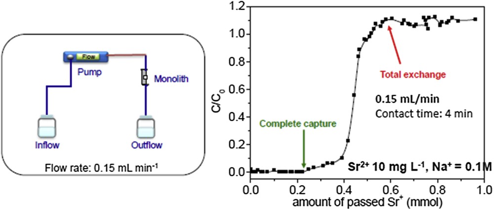
Breakthrough curve of Sr2+ removal from aqueous saline solution with LTA-monolith with a skeleton made of aggregation of 1–2-micron size crystals (adapted from ref. [17]).
3.4 New perspectives for emerging applications with hierarchical monoliths
3.4.1 Hierarchical zeolite monoliths with nanocrystals
LTA-monoliths, which have a skeleton formed by the association of micron-sized crystals, have revealed great potential for Sr2+ removal from salty effluents at low flow rate (0.15 mL min−1) [17]. To improve the performance of LTA-monoliths another synthesis strategy has been developed to produce LTA-monoliths with a skeleton formed by the association of nanocrystals in order to further increase the accessibility to the active sites and possibly enabling operating at higher flow rates. To reach this goal, the nucleation and growth steps of LTA zeolite crystals were separated. The pseudomorphic transformation conditions of silica monolith into LTA-monolith were modified (initially 100 °C for 18 h) and an ageing step of 24 h at 40 °C was proven to maximize the formation of a maximum of nuclei before the crystal growth started (done in a second step at a low temperature of 70 °C for 24 h). A very homogeneous monolith was obtained exhibiting a macroporosity similar to that of the parent silica monolith (Fig. 15). This new LTA-monolith (nanocrystals) will be tested in radioactive cation-exchange in further studies.

SEM pictures of (left) silica monolith and (right) LTA-monolith with a skeleton made of aggregation of nanocrystals.
3.4.2 In-situ synthesis of NiMoS2 into hierarchical monoliths
MoS2 promoted by Ni (NiMoS2) is a very efficient hydrotreatment catalyst. NiMoS2 is usually supported on alumina and used in a packed bed. The surface properties and the morphology of NiMoS2 are of prime importance for its catalytic performances: the more active sites are obtained when the lamellar structure of MoS2 presents a small amount of layers stacked with Ni at the edges of these layers. The effect of Ni in MoS2 catalysts has been attributed to the amount of Ni atoms that can be accommodated on the edges of MoS2 layers and also to the electronic transfer that the Ni atom induces on Mo atoms located at these sites [45,46]. To improve NiMoS2 performance, there is a need to enhance its structuration and favor these edges. Different strategies have been used, for example, by creating mesopores into the structure [47] or by developing nanoparticle synthesis [48]. The latter can be done with ionic liquid leading to an aggregation of self-supported nanoparticles [48]. However the industrial approach uses polyoxometallate (NiMo) Kegion cations adsorbed on mesoporous alumina followed by a thermal decomposition and a sulfuration step with H2S. We have developed an original in-situ synthesis of NiMoS2 nanoparticles inside the monolith without using a sulfuration step. The monolith was impregnated with an aqueous solution of (NH4)2MoS4, dried, and reimpregnated with a solution of Ni(NO3)2 and dried. The monolith becomes dark grey, characteristic for the formation of the NiMoS3 phase, which transforms into NiMoS2 after heating treatment at 550 °C under Ar. Nanoparticles of NiMoS2 are present as aggregates at the surface of the macropores and also as well-defined individual nanoparticles of 30 nm inside the mesopores featuring an important number of edges (Fig. 16). An optimization of this synthesis to concentrate the NiMoS2 nanoparticles inside the mesoporosity could lead to new improvements in hydrotreatment processes. However, in order to be tested in flow applications, an improved strategy of cladding the monolith has to be found, as this catalytic reaction is performed at high temperature (400 °C) where the Teflon clad decomposes.

Nanoparticle of NiMoS2 formed in-situ the mesoporosity of a silica monolith.
3.4.3 Carbon-coated hierarchical monoliths and carbon-monolith replicas
Because of their inherent properties, i.e. electrical and thermal conductivity, chemical inertness, thermal stability, low cost, and their ability to provide high surface areas, carbon-based porous materials are of great interest. They offer a wide range of applications, particularly when electrical and/or thermal conductivity is needed. Thus, porous carbons have been widely used as electrocatalysts, (electro)catalytic supports, electrode materials and hosts for gas adsorptive separation or storage (e.g., hydrogen, carbon dioxide). In the same vein as silica monoliths, carbon monoliths used as electrodes have the potential to provide efficient transport routes and easy access of the electrolyte and reagents to the whole system. As an example, carbon monoliths with an inhomogeneous macroporous network have been employed as supports for enzymatic electrocatalysis [49–54]. Amongst the different synthetic pathways developed to design porous monolithic carbons, we recently proposed the coating of hierarchical silica monoliths via the hydrothermal carbonization of (poly)saccharides such as glucose, sucrose and starch [55]. The silica monoliths were amino-functionalized before use in such a way that the isoelectric point of the silica-based surface could be shifted from pH 2 to pH 5, beneficial for an efficient hydrothermal carbon coating. After hydrothermal treatment and pyrolysis under an inert atmosphere carbon-coated monoliths have been obtained with a partial or a total filling of the mesoporous network depending on the amount of sugar used. Carbon monolithic replicas could be obtained after silica removal. BET surface area and pore volume up to 1400 m2 g−1 and 3.1 mL g−1, respectively, were reached without changing the homogeneous macroporous network and the monolithic aspect of the parent monolith. These carbon monoliths were used as sulfur hosts for lithium–sulfur batteries. However, due to a high porous volume, the carbon replicas were rather fragile as compared with the native silica monoliths. A carbon-coated silica monolith could be used instead to keep mechanical stability. Numerous promising applications are expected, particularly for continuous flow electrocatalysis, bio-electrocatalysis, but also catalytic reactions needing heat transfer control.
3.4.4 MCM-41 hierarchical monoliths with bi- or trimodal porosity
The amorphous silica monolith skeleton has been transformed into MCM-41 by pseudomorphic transformation by replacing the second step in alkaline medium (ammonia) of the synthesis by a treatment employing a surfactant (cetyltrimethylammonium bromide (CTAB)) and NaOH. The conditions for MCM-41 synthesis were adapted to achieve a rate of silica dissolution equivalent to the rate of MCM-41 formation [8]. Because dissolution of silica is fast as well as MCM-41 formation, pseudomorphic transformation was performed on a monolith with a low condensation state of silica issued from the first sol–gel step in acidic medium. Starting from silica monolith after the second basic step, where silica is well condensed, leads to a rapid formation of MCM-41 at the external macroscopic surface of the monolith in the form of a screw. The synthesis of MCM-41 monolith has been recently improved (1 SiO2: 0.6 CTAB: x NaOH: 400H2O, 6 days at 115 °C) in order to tune the mesoporous network. For instance an MCM-41 material with a single pore size (3.5 nm) templated by CTAB micelles was obtained with x = 0.2 and a material with a double interconnected porosity with pore sizes of 3.5 and 10 nm was obtained for x = 0.1. The secondary larger mesoporosity arises from regularly distributed voids in between MCM-41 domains with large wall thickness, as previously observed for pseudomorphic transformation of spherical particles [35]. To avoid the secondary large mesoporosity, the porosity of the silica skeleton has to be totally filled by MCM-41 domains and this was achieved by synthesizing an MCM-41 phase with a larger pore volume. The increase of NaOH amount in MCM-41 synthesis leads to a material with thinner walls and consequently higher pore volume and surface area. Such materials are promising candidates to be used as model materials to understand diffusion phenomena in systems with well-defined pores. Previously we have shown by PFG NMR measurements of n-hexane diffusion in MCM-41 particles obtained by pseudomorphic synthesis [35] that the addition of a second mesoporosity connected to the exterior of the particle enhances the diffusion rate into the smaller mesopores. Such new hierarchical monoliths with well-defined pores at 2 or 3 scales could represent valuable model materials to understand diffusion phenomena in complex multiscale porous media.
3.4.5 TiO2 hierarchical monoliths as promising photocatalysts
TiO2 under anatase form is an efficient photocatalyst under UV for the degradation of pollutants in air and in aqueous solution. Most of the time it is used as a suspension of nanoparticles as the well-known P25 of Degussa, with the difficulty to handle nanoparticles and to separate them from liquid medium. Shaping TiO2 as monolithic bodies could be an issue to continuous flow processes of wastewater treatment by the advanced oxidation process. To test the photocatalytic activity of TiO2 monoliths with hierarchical porosity, we first performed a preliminary test in batch to remove a dye, Orange-G, in aqueous solution. The TiO2 monolith synthesis was adapted from the Nakanishi group [56,57]. TiO2 monoliths (as well as Al2O3 monoliths [15,58]) are more difficult to obtain as a strong shrinkage occurs during gelation. TiO2 monoliths with 3 mm diameter were obtained in pieces of 1–2 cm length and the skeleton consists of an agglomeration of anatase crystallites. Monoliths of 1 cm length were immersed in a solution of 80 mg L−1 of dye and were exposed either to UV lamp or sunlight. A blank test was also performed in the dark. After 5 h under UV lamp and sunlight, the concentration of dye has decreased to 53.9 ± 0.1 and 49.5 ± 1.05 mg L−1, respectively, revealing a catalytic activity for dye degradation by TiO2 monoliths. In the dark, the concentration of dye was 61.3 ± 0.1 mg L−1, revealing some adsorption phenomenon of the dye into the monolith. Longer exposition time to UV and light should be performed, as the kinetic of dye degradation in static is slow. This preliminary result evidences the possibility to use TiO2 monolith in photocatalytic processes.
New compositions of hierarchical porous monoliths with a homogeneous macropores network have been recently synthesized in the literature: CuBTC [59], zirconium phosphate [60], titanium nitride [61], cordierite [62], Layered Double Hydroxyde (LDH) [63], CaTiO3, SrTiO3 and BaTiO3 Perovskite [64] opening the route for a wide development of these novel kind of monolithic microreactors in catalysis and in adsorption.
4 Conclusions
Shaping catalysts or adsorbents as monolithic bodies with well-defined hierarchical porosity (macro-/mesoporosity) shows numerous advantages over classical employment of particles in packed bed or batches. It drastically improves their efficiency, selectivity and lifetime. Several examples of improved catalytic reactions or adsorption processes in liquid media have been highlighted using this novel class of monolithic microreactors, owing essentially to the homogeneous network of macropores leading to an equal and homogeneous access of the molecules to the mesopores where the active sites are located. The contact time of the reaction can be precisely controlled with such a kind of microreactor, opening the route to the improvement of numerous reactions.
Monoliths with small macropores (1.5 microns) are commercialized as chromatographic columns, but lead to large pressure drops. We envision that monoliths with larger macropores of a size of 5 microns have a place on the market of catalysis and adsorption as they do not develop pressure drops and achieve superior outcomes. Efforts for generalizing the use of these new microreactors must be paid towards improvement of the cladding procedure. In chromatography, Merck is using a polymer (PEEK) clad, some other groups used epoxy resins. Here, we have used a Teflon heat shrinkable clad. These claddings are designed for low temperature operation, lower than 40–50 °C for polymers and 100 °C for Teflon gain. Thus, a new kind of cladding strategy must be disclosed in order to widen the employment of these very useful microreactors to a wide spectrum of applications.
Acknowledgements
This research was funded by the European Community's Seventh Framework Program through the Marie-Curie Initial Training Network Nano-Host, under Grant Agreement ITN No. 215193-2, by the ANR french agency (Project Labex Chemisyst, ANR-10-LABX-05-01 and project Nanochalco, ANR 2011BS0801501), by CNRS (INC) and by TOTAL SA.