

1 Introduction
Due to the manifold applications of crystalline zeolites, increasing attention worldwide has been paid to the preparation of zeolites in forms suitable for practical utilization and to the development of methods for producing zeolite objects (films, membranes, pellets, microspheres …) with controllable thicknesses. Among these zeolite objects, supported zeolite layers have great potential and great utilities and their functions and application can be easily tuned by changing the zeolite species used to generate them. Zeolite films and membranes are believed to be important materials in the technology era with novel emerging applications in various fields such as membrane separation [1,2], catalysis [3–5], chemical sensors [6,7], anti-microbial coating [8,9], microelectronic devices [10–13] and corrosion resistance [14–16].
Efforts have been devoted to the development of different methods for the synthesis of supported zeolite films such as in-situ crystallization and pre-seeding with regrowth or sticking of nanocrystals on a surface [2]. In-situ crystallization can be realized in a traditional liquid phase [1,17,18], by solid state transformation [19] or microwave-assisted hydrothermal synthesis [20] while pre-seeding methods were achieved in alkaline [21] and fluoride [22] routes. The vapor phase transport method was also used for the synthesis of MFI (Mobil Five) membranes [23]. But unfortunately, most of the efforts focused on the study of single-layered zeolite film/membranes composed of one type of zeolite. If zeolitic materials are selective in size and shape and display various relevant properties depending on their nature or chemical composition, the combination of different zeolites might be a wise solution to enhance some industrial applications. As a consequence, two-layered films of different zeolites were developed to improve the efficiency of separation membranes [24–26] or to combine the extreme properties of microporous materials. For example, the development of methods to produce bi-layer zeolite films composed of high and low silica zeolites on aluminum substrates were done by our team in order to reduce the molecular contamination in satellites [27–30]. In those bi-layer films, the bottom layer is represented by the ZSM-5 (Zeolite Socony Mobile 5) (MFI structure type) zeolite while EMC-1 (Elf Mulhouse Chemistry 1) zeolite (FAU (faujasite) structure type) or EMC-2 (Elf Mulhouse Chemistry 2) zeolite (EMT (Elf Mulhouse Chemistry Two) structure type) or beta zeolite forms the top layer of the material [27–30]. In this paper MFI-type zeolites and FAU-type zeolites are highlighted due to their great potential for industrial applications.
The MFI structure type is characterized by a porous system formed by the interconnection of straight circular channels (5.4 Å × 5.6 Å) with sinusoidal and elliptical channels (5.1 Å × 5.4 Å) which is very interesting for some environmental applications such as the removal and/or remediation of anions in water [31] and volatile organic compounds (VOCs) [32–34]. Depending on the silicon to aluminum molar ratio of the microporous framework, ZSM-5 (Si/Al < 500) and silicalite-1 (Si/Al > 500) are two zeolites presenting the MFI structure [33–37].
FAU-type zeolite is of particular interest due to its high aluminum content, i.e. its hydrophilicity. Its pores are composed of supercages, with a free diameter of 11.6 Å, interconnected through circular 12-member-ring (MR) apertures with a diameter of 7.4 Å [38].
Conventional NaY zeolite (FAU-structure type) presents a silicon-to-aluminum molar ratio between 1.5 and 2.5. High silica FAU-type zeolite, with a silicon to aluminum molar ratio between 3 and 5, can be synthesized directly by using specific structure-directing agents (SDAs) in a synthesis hydrogel. Thus, Guth and co-workers reported the crystallization of a high silica FAU-type zeolite commonly named EMC-1 (Elf Mulhouse Chemistry One) by using the 15-crown-5 ether as SDA [38–41].
Consequently, the scope of the present work was to produce zeolite bi-layered films composed of high (ZSM-5 zeolite) and low (EMC-1 and NaY zeolites) silica zeolites on alumina plates as represented in Fig. 1. Three different zeolite bi-layered films were synthesized, ZSM-5/ZSM-5, ZSM-5/EMC-1 and NaY/ZSM-5. The crystallinity, homogeneity, thickness and Si/Al molar ratio of the both layers as well as other microstructural properties are investigated by X-ray diffraction (XRD), scanning electron microscopy (SEM), X-ray fluorescence (XRF) and nitrogen sorption measurements. The weight of the zeolite layer was also estimated by nitrogen sorption measurements using the method of mass assessment.
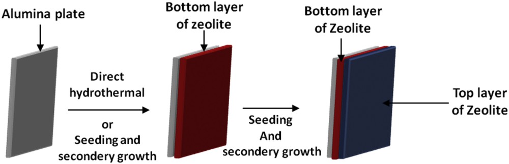
Scheme representing the overall method of the synthesis of a bi-layer zeolite film on alumina plates.
2 Experimental section
2.1 Materials
The chemical reagents used in this work were aluminum powder (99.95 wt %, Aldrich), sodium hydroxide (NaOH, 99.99 wt %, Aldrich), tetraethylorthosilicate (TEOS, 98 wt %, Aldrich), tetrapropylammonium hydroxide (TPAOH, 40 wt %, aqueous solution, Aldrich), aluminum isopropoxide (98 wt %, Aldrich), colloidal silica (Ludox HS-40, Aldrich), tetramethylammonium hydroxide pentahydrate (TMAOH, 5H2O, 98 wt %, Alfa Aesar), sodium aluminate (57 wt % Al2O3, 40 wt % Na2O, Strem Chemicals), 15-crown-5 (98 wt %, Alfa Aesar) sodium metasilicate (Na2SiO3·9H2O > 98%, Sigma) with aluminum sulfate-18-hydrate (Al2(SO4)3, Aldrich), ethanol and distilled water. All the chemical reagents were of analytical grade.
Pieces of 2 × 2 cm2 of alumina (0.2 cm thick) were purchased from Final Matériaux Avancés (Wissembourg, France).
2.2 Pre-treatment of the substrates
2.2.1 Before synthesis of the bottom layer of ZSM-5 zeolite
Pre-treatment of the substrates was fully described in a previous paper [14,30] and consists of cleaning the plates in an aqueous solution of a detergent (Alconox, 3 g in 400 mL of distilled water) heated to 60 °C for 1 h [30, 32]. They were then rinsed with distilled water, dried at 70 °C and cooled down to ambient temperature.
2.2.2 Before synthesis of bottom layer of NaY zeolite
Pre-treatment of the substrates was fully described by M. Lassinantti and co-authors [42] and consists of cleaning the plates in acetone for 5 min using an ultrasonic bath. After ultrasonification, the substrates were boiled for 5 min in an alkaline solution having the following volume composition 5H2O:1H2O2:1NH3 (30% H2O2 and 25wt % NH3 solution) and then in an acidic solution with a volume composition 6H2O:1H2O2:1HCl (30% H2O2, 37% HCl).
2.3 Synthesis of bi-layer zeolite films (ZSM-5/ZSM-5 and ZSM-5/EMC-1)
2.3.1 Synthesis of the ZSM-5 bottom layer (MFI structure-type)
The bottom layer was formed by in-situ crystallization of the MFI-type zeolite [30]. The molar composition of the clear solution used for the synthesis of ZSM-5 zeolite films was: 0.08 (TPA)2O:0.32 Na2O:1 SiO2:92H2O:0.0009 Al2O3. Three vertically alumina plates fixed on a PTFE (Teflon®) holder were immersed into 20 g of solution, placed in a 48 mL Teflon® lined stainless steel autoclave (Top Industrie, Fr.) and heated at 180 °C for 24 h. After hydrothermal synthesis, the coated substrates were rinsed with distilled water and placed in an ultrasonic bath for a few minutes to remove the loosely attached crystals. To remove the tetrapropylammonium cations (TPA+) occluded in the zeolite pores, the samples were calcined at 550 °C with a low temperature ramp of 1 °C min−1 to avoid cracks in the films [43].
2.3.2 Synthesis of the ZSM-5 top layer (MFI structure-type)
2.3.2.1 Seed preparation
The silicalite-1 seed crystals were synthesized according to the procedure published by Lew et al. [44]. Tetraethylorthosilicate (TEOS), ethanol (100%) and distilled water were mixed in a polypropylene flask. After the tetrapropylammonium hydroxide (TPAOH; 40 wt %) was added dropwise to the mixture, a clear homogeneous solution was formed with the following molar composition: TPAOH:3 SiO2:52.4H2O:25.1 EtOH. The solution was aged at room temperature for 1 day under stirring. Then, the polypropylene bottle is placed in a 60 °C oil bath under stirring. The solutions were kept under these conditions for two days and were then quickly transferred into Teflon-lined autoclaves. The autoclaves were placed into a preheated oven at 100 °C. Zeolite nanocrystals were recovered by centrifugation at 20,000 rpm for 1 h. The resulting nanocrystal cakes were purified by three repeated cycles of centrifugation, decanting, and ultrasonic redispersion in distilled water. They were then dried at 95 °C and calcined at 550° C for 5 h.
2.3.2.2 Seeding step and secondary growth method
The alumina plate substrates coated by the first layer of ZSM-5 zeolite was placed for 1 h in a cationic polymer solution (poly(diallyldimethylammonium) chloride 1 wt % aqueous solution, Aldrich) to reverse the negative charge of the ZSM-5 layer surface (by dip coating) [27–29]. The positively charged ZSM-5 bottom layer was then washed with ammonia solution (0.1 M) and then with distilled water in order to eliminate the excess of cationic polymer. It was then immersed in the zeolite seed colloidal suspension described in Section 2.3.2.1 for 1 h using the dip coating technique. Strong electrostatic interactions between the positively charged surface and the negatively charged zeolite nanocrystals are thus promoted. The preseeded film was then dried at 50 °C for 3 h.
The secondary growth step is launched by immersing the first coated and preseeded substrates in the same clear solution used for the synthesis of the ZSM-5 bottom layer described in Section 2.3.1 at 180 °C for 48 h. The substrates are rinsed with copious amounts of distilled water, placed in an ultrasonic bath for a few minutes to remove the loosely attached crystals and dried at 70 °C. In order to remove the templates occluded in zeolite pores (tetrapropylammonium cations), the final samples are calcined at 550 °C with a low temperature ramp of 1 °C min-1 to avoid cracks in the films [27–30, 43].
2.3.3 Synthesis of the EMC-1 top layer (FAU structure-type)
2.3.3.1 Seed preparation
The preparation of faujasite seed crystals and procedure for seeding the substrates is adapted from previous papers [27, 28, 45]. The precursor solution has a molecular composition of 1 Al2O3:3.2 SiO2:3.4 TMAOH:123H2O and was hydrothermally treated at 100 °C for 6 days in a polypropylene bottle. The resulting colloidal suspension of FAU-type seeds was washed by several centrifugation-scattering cycles in distilled water until the pH reached 9. A small amount of the obtained suspension was then dried by lyophilization to have a fine powder suitable for characterization techniques.
2.3.3.2 Seeding step and secondary growth method
The seeding step procedure applied for the synthesis of the EMC-1 top layer was similar to the one used for the synthesis of the ZSM-5 top layer (Section 2.3.2.2).
The secondary growth step is launched by immersing the first coated and preseeded substrates in a gel of molar composition 2.1 Na2O:10 SiO2:1 Al2O3:0.5 15-crown-5:100H2O [39]. The mixture was then placed in a 48 mL Teflon® lined stainless steel autoclave (Top Industrie, Fr.) at 110 °C for 15 days [39]. After the synthesis, the substrates are rinsed with copious amounts of distilled water, placed in an ultrasonic bath for a few minutes to remove the loosely attached crystals and dried at 70 °C. In order to remove the templates occluded in zeolite pores (tetraethyl ammonium for the MFI film and crown ether for the EMC-1 film), the final samples are calcined at 550 °C with a plateau at 380 °C and a low temperature ramp of 1 °C per minute to avoid cracks in the films [43].
2.4 Synthesis of bi-layer zeolite films (NaY/ZSM-5)
2.4.1 Synthesis of the NaY bottom layer (FAU structure-type)
Following the cleaning step described in Section 2.2.2, the substrates were treated for 1 h in a solution containing cationic polymer solution (poly(diallyldimethylammonium) chloride 1 wt % aqueous solution, Aldrich), adjusted to pH 8.0 by addition of a dilute ammonia solution. The substrates were rinsed in a 0.1 M ammonia solution to remove polymer excess. Then, the modified substrates were immersed for 1 h in the zeolite seed colloidal suspension described in Section 2.3.3.1. After the adsorption of faujasite seeds, the substrates were rinsed in a dilute ammonia solution to remove excess crystals. Three seeded substrates were then immediately placed vertically in a synthesis gel placed in a 48 mL Teflon® lined stainless steel autoclave (Top Industrie, France) at 100 °C for 21 h. The molar composition of the synthesis gel was 14 N2O:1 Al2O3:10 SiO2:798H2O:3 Na2SO4. The gel was prepared by mixing an aqueous solution of sodium metasilicate (Na2SiO3.9H2O > 98%) with aluminum sulfate-18-hydrate dissolved in a 1.0 M sodium hydroxide solution. The gel was homogenized under stirring for 2 h. After cooling, the samples were rinsed in a dilute ammonia solution. In order to investigate the events taking place in the bulk of the film synthesis solution, the bulk product was purified by sedimentation and redispersion in dilute ammonia solution. The purification step was repeated twice, and the dispersion was air dried at 100 °C [42].
2.4.2 Synthesis of the MFI top layer by seeding (MFI structure-type)
After the synthesis of the NaY bottom layer, the top ZSM-5 layer was synthesized using the method of seeding and secondary growth described above in Section 2.3.2.
2.5 Characterization methods
The zeta potentials of the silicalite-1 and faujasite zeolite seeds were measured by laser doppler micro-electrophoresis, (Malvern nano-ZS). Once dried by lyophilization, the seeds are characterized at room temperature by using a conventionnal X-ray diffractometer and a scanning electron microscope (SEM). The films were examined by X-ray diffraction (XRD) using a PANalytical, X’Pert Pro diffractometer fitted for flat samples and unit cell parameters were refined thanks to the Win X Pow software. The morphology, homogeneity and thickness of the films were investigated with a SEM (Philips XL30 FEG). For thickness assessment, the films were polished to remove crystals attached on the edges of the substrates.
Complete nitrogen gas adsorption–desorption isotherms were obtained with a Micromeritics ASAP 2420 apparatus with adapted tubes for the coated substrate dimensions. For better accuracy two alumina substrates are introduced in the tube. The mass of the substrates coated by the zeolite films was assessed by weighing. The microporous volume was separated from the mesoporous volume by the t-plot method. Prior to experiments, the samples were outgassed to a residual pressure of less than 0.8 Pa at 350 °C for 15 h.
The Si/Al molar ratio of the films was estimated and compared using two different methods including X-Ray Fluorescence (Philips, Magic X) and X-Ray diffraction. In the latter case, the Si/Al molar ratio of the ZSM-5 bottom and top layers and ZSM-5/ZSM-5 bi-layer films was determined from the refinement of the unit cell parameters of the non-calcined ZSM-5 films. According to Guth et al. [46], a linear relation exists between the silicon to aluminum ratio of the MFI-type zeolites and its unit cell volume in certain conditions.
3 Results and discussion
3.1 Synthesis of the ZSM-5 bottom layer
Under optimized conditions of the direct one-step synthesis, after 24 h of hydrothermal treatment, a continuous film of zeolite ZSM-5 is obtained on the alumina plate as shown in the SEM image (Fig. 2b) [47]. In comparison with the surface of the alumina plate, the asperity of the surface is observed (Fig. 2a). The cross-sectional view of the film is shown in Fig. 2c where a 9 μm thin coating is observed.
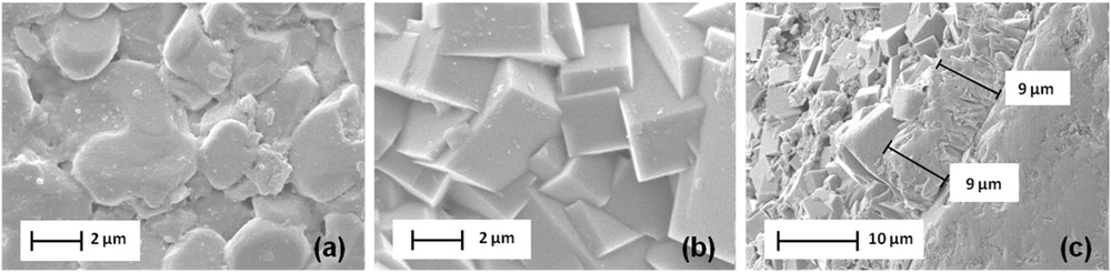
SEM images of (a) the surface of the alumina plate (b) the surface of the ZSM-5 bottom layer and (c) its thickness.
The XRD pattern of the calcined ZSM-5 bottom layer shows a well crystalline zeolite film with different reflection intensities, which are characteristic of the MFI structure (Fig. 3b) [30, 34–36, 47, 48]. Five additional peaks characteristic of the alumina (α-Al2O3) are also observed. These five peaks were also observed in the XRD pattern of the uncoated alumina plate (Fig. 3a). XRD patterns of the calcined ZSM-5 zeolite layer can be indexed to the monoclinic symmetry, which reveals that the silicon to aluminum molar ratio is higher than 70 [47, 49]. More precisely, the silicon to aluminum ratio was assessed to be 185 according to the relationship existing between the volume and the aluminum atom number of the unit cell [30, 46, 47]. In comparison to the Si/Al ratio with a value of 600 in the MFI synthesis solution, it can be concluded that some of the aluminum from the alumina substrate is incorporated into the zeolite coating.
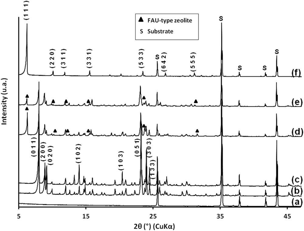
XRD patterns of (a) the alumina plate, (b) the ZSM-5 bottom layer synthesized on the alumina plate, (c) the ZSM-5/ZSM-5 bi-layer film, (d) the ZSM-5/EMC-1 bi-layer film, (e) the NaY/ZSM-5 bi-layer film and (f) the NaY bottom layer on the alumina plate.
3.2 Synthesis of the ZSM-5 top layer (ZSM-5/ZSM-5)
The top layer of ZSM-5 zeolite was synthesized using the secondary growth method, using the MFI seeds deposited by dip coating on the MFI coated alumina substrate [47].
The seeds were characterized by XRD and SEM. The XRD pattern corresponds to the MFI-type zeolite with a slight broadening of the peaks due to the small size of the crystals (Fig. 4a). The scanning electron microscopy image shows spherical crystals with an average size of 70 nm (Fig. 4b). The zeta potential of the silicalite-1 zeolite nanocrystals was estimated to be −35 mV.
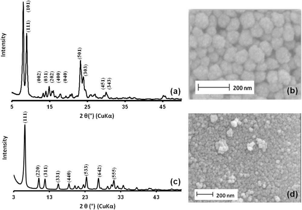
XRD patterns and SEM images of silicalite-1 zeolite seeds (a and b) and faujasite zeolite seeds (c and d).
Electrostatic interactions between the positively charged ZSM-5 surface (charge reversion with cationic polymer) and seeds are thus promoted. The seeding step efficiency was assessed by SEM (Fig. 5a) [47]. In Fig. 5a, the presence of silicalite-1 seeds attached to the ZSM-5 bottom layer is then evidenced. The SEM image corroborates the small size of the silicalite-1 crystals as well as the homogeneous attachment to the substrate.
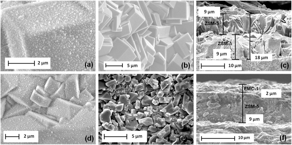
SEM images of (a) the seeded bottom layer of ZSM-5 zeolite, (b) the ZSM-5 top layer surface after hydrothermal treatment on the seeded substrate, (c) the thickness of the ZSM-5/ZSM-5 bi-layer film, (d) the seeded bottom layer of ZSM-5 zeolite with nanosized crystals of faujasite zeolite, (e) the EMC-1 top layer surface and (f) the thickness of the ZSM-5/EMC-1 bi-layer film.
The seeded and calcined supports were then immersed in a gel for the synthesis of ZSM-5 zeolite as described above and submitted to a hydrothermal treatment for 24 h. After this crystallization time, a continuous and dense layer of MFI zeolite is observed by SEM (Fig. 5b). The ZSM-5 bottom layer is no longer visible. The bi-layer film thickness was evaluated by SEM cross-view observations and is around 18 μm, while the bottom and top layer are respectively 9 μm thick (Fig. 5c).
The XRD-pattern shows different reflection intensities, which are characteristic of the MFI structure (Fig. 3c) [30, 34–36, 47, 48]. Based on each zeolite film thickness, the volume of a given coated zeolite can be deduced. According to the zeolite density (calculated as in bulk) and the dimensions of the zeolite film, the composition of the film can be evaluated to be around 50 wt % for the ZSM-5 bottom layer and 50 wt % for the ZSM-5 top layer (See Table 1). As described thereafter, this result is also confirmed by nitrogen sorption measurements. The silicon to aluminum ratio of the bi-layer was increased from 185 to 305 according to the relationship existing between the volume and the aluminum atom number of the unit cell [46].
Useful data for the determination of the bi-layer film composition.
| Bi-layer zeolite films | Layer thickness a (μm) | Vlayer (cm3/g STP) | Vlayerb (cm3/g) | Zeolite weight per substratec (mg) | Composition of the bi-layer filmc (wt %) | Composition of the bi-layer filmd (wt.%) | |
| ZSM-5/ZSM-5 | ZSM-5* | 9 | 1.32 | 2.04 × 10⁻³ | ∼16.3 | 50.8 | 50 |
| ZSM-5** | 9 | 1.26 | 1.95 × 10⁻³ | ∼15.8 | 49.2 | 50 | |
| ZSM-5/EMC-1 | ZSM-5* | 9 | 1.32 | 2.04 × 10⁻³ | ∼16.3 | 86.2 | 85.4 |
| EMC-1** | 2 | 0.34 | 0.53 × 10⁻³ | ∼2.6 | 13.8 | 14.6 | |
| NaY/ZSM-5 | NaY* | 3 | 0.52 | 0.80 × 10⁻³ | ∼3.6 | 14.3 | 15.1 |
| ZSM-5** | 12 | 1.59 | 2.46 × 10⁻³ | ∼21.5 | 85.7 | 84.9 |
a Film thickness determined from SEM observations.
b Micropore volume of the zeolite layers determined from N2 sorption results.
c Determined from N2 sorption results.
d Determined from the density of the zeolite and the dimensions of the layer (density of ZSM-5 is 1.78 g cm−3, EMC-1 is 1.37 g cm−3 and NaY is 1.27 g cm−3)
3.3 Synthesis of the EMC-1 top layer (ZSM-5/EMC-1)
The top layer of EMC-1 zeolite was synthesized by the secondary growth method, using NaX FAU-type seeds deposited by dip coating on the MFI coated alumina substrates [28].
The seeds were characterized by XRD and SEM. The XRD pattern of the seeding particles corresponds to the X zeolite with a slight broadening of the peaks due to the small size of the crystals (Fig. 4c). This fact is backed by the SEM image of the sample, showing crystals of 40 nm size (Fig. 4d). The zeta potential of the faujasite nanocrystals was −68 Mv [28]. Electrostatic interactions between the positively charged ZSM-5 surface (charge reversion) and NaX seeds are thus promoted. The seeding step efficiency was assessed by SEM inspection of the MFI coated substrate prior to and after the immersion in the colloidal suspension of seeds (Fig. 5d). In Fig. 5d, the presence of faujasite seeds attached to the ZSM-5 bottom layer is then evidenced. The SEM image corroborates the small size of the FAU-type crystals as well as the homogeneous attachment to the substrate.
The seeded and uncalcined supports were then immersed in a conventional gel for the EMC-1 zeolite synthesis as described above and subjected to a hydrothermal treatment for 15 days. After this crystallization time, a continuous and dense layer of EMC-1 zeolite is observed by SEM (Fig. 5e). The bipyramidal shape crystals are typical of the EMC-1 zeolite morphology and the ZSM-5 bottom layer is no longer visible [28]. The existence of both ZSM-5 and EMC-1 zeolites in the bi-layer film is confirmed by XRD patterns as reported in Fig. 3d where peaks corresponding to both zeolite phases are observed. The bi-layer film thickness was evaluated by the SEM cross-sectional view image and is around 11 μm, while the bottom and top layers are respectively 9 μm and 2 μm thick (Fig. 5f). Based on each zeolite film thickness, the volume of a given coated zeolite can be deduced. According to the zeolite density (calculated as in the bulk), the composition of the bi-layer film can be evaluated to be 85.4 wt % for the ZSM-5 bottom layer and 14.6 wt.% for the EMC-1 top layer (Table 1). As described thereafter, this result is also confirmed by nitrogen sorption measurements.
3.4 Synthesis of the NaY zeolite bottom layer (NaY/ZSM-5)
The bottom layer of NaY zeolite was synthesized by the secondary growth method, using NaX seeds deposited by dip coating directly on the alumina substrate. Electrostatic interactions between the positively charged alumina plate surface and seeds are thus promoted. The seeding step efficiency was assessed by SEM. In Fig. 6a, the presence of faujasite seeds attached to the alumina plate is evidenced. After the crystallization step, a homogeneous film constituted by bipyramidal crystals characteristic of the FAU-type zeolite is observed (Fig. 6b). A cross-sectional view of the film is shown in Fig. 6c where a 3 μm thin coating is observed. The XRD-pattern shows different reflection intensities, which are characteristic of the NaY zeolite (Fig. 3f) [50]. The silicon to aluminum molar ratio was assessed to be 1.53.
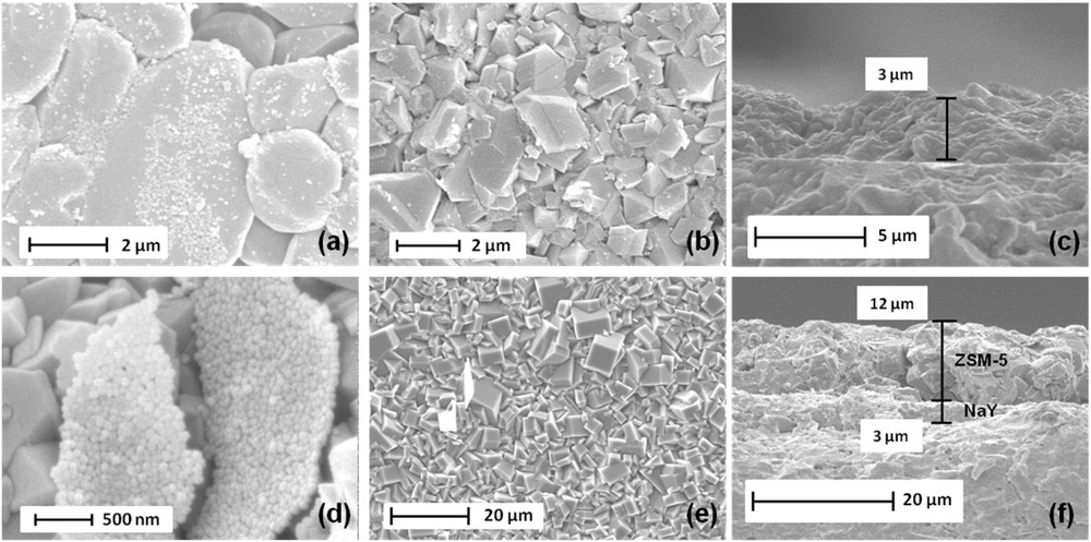
SEM images of (a) the seeded alumina plate with nanosized crystals of FAU-type zeolite, (b) the NaY bottom layer surface synthesized on the alumina plate after hydrothermal treatment on the seeded substrate, (c) the thickness of the NaY bottom layer, (d) the seeded bottom layer of NaY zeolite with nanosized crystals of MFI-type zeolite, (e) the ZSM-5 top layer surface after hydrothermal treatment on the seeded substrate, (f) the thickness of the NaY/ZSM-5 bi-layer film.
3.5 Synthesis of the ZSM-5 top layer (NaY/ZSM-5)
The ZSM-5 top layer was synthesized by the secondary growth method as shown above, using silicalite-1 seeds deposited by dip coating on the NaY coated alumina substrates. The seeding step efficiency was assessed by SEM inspection of the FAU coated substrate prior and after the immersion in the colloidal suspension of seeds (Fig. 6b and 6d). In Fig. 6d, the presence of silicalite-1 seeds (agglomerated particles) attached to the NaY bottom layer is then evidenced.
The seeded supports were then immersed in a gel as described above and submitted to a hydrothermal treatment for 24 h. After this crystallization time, a continuous and dense layer of ZSM-5 zeolite is observed by SEM (Fig. 6e). The prismatic shape crystals typical of the MFI-type zeolite morphology eclipsed the NaY bottom layer. The bi-layer film thickness was evaluated by SEM cross-view observations and is around 15 μm, while the bottom and top layers are respectively 3 μm and 12 μm thick (Fig. 6f). The existence of both NaY and ZSM-5 zeolites in the bi-layer film is confirmed by XRD patterns as reported in Fig. 3e where peaks belonging to the two different phases are observed. XRD patterns of the calcined ZSM-5 zeolite top layer can be indexed to the monoclinic symmetry, which reveals that the silicon to aluminum molar ratio is higher than 70 [47, 49]. More precisely, the silicon to aluminum ratio was assessed to be 76 according to the relationship existing between the volume and the aluminum atom number of the unit cell [30, 46, 47]. Based on each zeolite layer thickness, the volume of a given coated zeolite can be deduced. According to the zeolite density (calculated as in the bulk), the composition of the film can be evaluated to be around 15.1 wt % for the NaY bottom layer and 84.9 wt % for the ZSM-5 top layer (See Table 1). As described thereafter, this result is also confirmed by nitrogen sorption measurements.
3.6 Sorption properties
Nitrogen sorption properties of the uncoated alumina substrate and alumina substrates coated with mono or bi-layer zeolite films were investigated in order to assess the pore accessibility of the zeolite film. According to the IUPAC (International Union of Pure and Applied Chemistry) classification [51], isotherms reported in Fig. 7 are of type I and characteristic of pure microporous materials. This result confirms the SEM investigations done on the surface of the zeolite bottom and top layers where no inter-crystalline voids or cracks were observed. A step in the N2 adsorption–desorption isotherms of the bi-layer film composed of ZSM-5/ZSM-5 zeolites can be observed between 0.1 and 0.3 p/p0, which corresponds to a densification of the adsorbate phase [52]. This step seems to decrease by decreasing the Si/Al molar ratio of the ZSM-5 film. The isotherm corresponding to the bi-layer film composed of ZSM-5/ZSM-5 zeolites presents a total nitrogen adsorbed volume of 2.58 cm3/g STP (STP : Standard Temperature and Pressure) of sample (Fig. 7f), including the mass of the alumina plates, while the nitrogen adsorbed volume of the bottom layer is 1.32 cm3/g STP which corresponds to a microporous volume of 2.04.10−3 cm3/g (see Table 1 and Fig. 7c). The bi-layer film exhibits logically a higher nitrogen adsorbed volume representing an increase of 1.26 cm3/g STP (which corresponds to a microporous volume of 1.95.10−3 cm3/g).
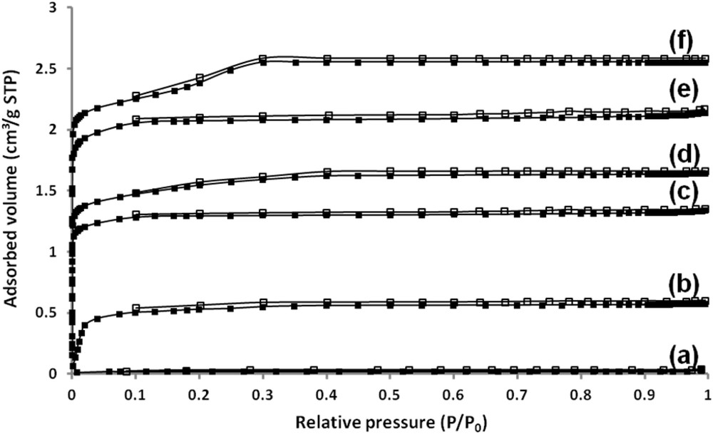
Nitrogen adsorption (filled symbol)/desorption (open symbol) isotherms at −196 °C for (a) the alumina plate, (b) The NaY bottom layer, (c) the ZSM-5 bottom layer, (d) the ZSM-5/EMC-1 bi-layer film, (e) the NaY/ZSM-5 bi-layer film and (f) the ZSM-5/ZSM-5 bi-layer film. The nitrogen adsorbed volume is expressed per gram of sample, including the mass of the substrates.
In the same way, the isotherm corresponding to the bi-layer film composed of ZSM-5 and EMC-1 zeolites presents a total nitrogen adsorbed volume of 1.66 cm3/g STP of sample (Fig. 7d), including the mass of alumina plates. The bi-layer film exhibits logically a higher nitrogen adsorbed volume representing an increase of 0.34 cm3/g STP (which corresponds to a microporous volume of 0.53.10−3 cm3/g) (see Table 1). The isotherm corresponding to the bi-layer film composed of NaY and ZSM-5 zeolites presents a total nitrogen adsorbed volume of 2.11 cm3/g STP of sample (Fig. 7e), including the mass of alumina plates, while the nitrogen adsorbed volume of the bottom layer is 0.52 cm3/g STP (Fig. 7b) which corresponds to a microporous volume of 0.80.10−3 cm3/g (see Table 1). The bi-layer film exhibits logically a higher nitrogen adsorbed volume representing an increase of 1.59 cm3/g STP (which corresponds to a microporous volume of 2.46.10−3 cm3/g).
As previously stated, the nitrogen sorption results represent also a reliable method for the determination of the mass composition of the bi-layer film. The first step consists of estimating the mass of the bottom layer by comparing the nitrogen adsorbed volume of the ZSM-5, EMC-1 and NaY films (V(sample)) to the nitrogen adsorbed volume of the equivalent powder (V(equivalent powder)) whose well known value is 120 cm3/g STP for ZSM-5, 207 for EMC-1 and 214 for NaY (which corresponds to a microporous volume of 0.19 cm3/g for ZSM-5 zeolite and 0.32 cm3/g for EMC-1 and NaY zeolites) [28, 30, 38, 47, 50]. A simple equation given below is basically used to calculate the amount of zeolite coated on the substrate (Eq. (1)) [27–30, 47]. The mass of the sample (mtotal(sample)), including the two alumina substrates and the zeolite layers (See Table 2), is determined by weighing.
| (1) |
The mass of the samples (mtotal(sample)), including the two alumina substrates and the zeolite layers, determined by weighing.
| Zeolite films | ZSM-5 | ZSM-5/ZSM-5 | ZSM-5/EMC-1 | NaY | NaY/ZSM-5 |
| mtotal (Sample)a (g) | 2.963 | 2.995 | 3.005 | 2.972 | 3.17 |
a The weights of the starting alumina substrates which have been coated are not exactly the same.
V stands for total nitrogen adsorbed volume expressed in cm3 g−1 STP and mtotal is the sample mass assessed by weighing in g.
Based on this equation, it could be inferred that each alumina substrate is coated with 16.3 mg of ZSM-5 zeolite for the bottom layer and 15.8 mg for the top layer in the bi-layer ZSM-5/ZSM-5 film. This bi-layer film is then composed of 50.8 wt % of the ZSM-5 bottom layer and 49.2 wt % of the ZSM-5 top layer (see Table 1). The same equation is used to determine the mass of NaY and EMC-1 zeolites forming the bottom layer or top layer of the two other bi-layer film. The nitrogen adsorbed volume of EMC-1 is deduced by subtracting the total nitrogen adsorbed volume of the bi-layer ZSM-5/EMC-1 film to the nitrogen adsorbed volume of the bottom ZSM-5 layer previously measured (0.34 cm3/g STP). The mass of the EMC-1 zeolite layer is then assessed to be 2.6 mg on each substrate. The nitrogen adsorbed volume of the equivalent EMC-1 powder was measured on EMC-1 powder synthesized under the same conditions (207 cm3/g STP). Consequently, the bi-layer film is composed of 86.2 wt % of ZSM-5 zeolite and 13.8 wt.% of EMC-1 zeolite (see Table 1). For the bi-layer NaY/ZSM-5 film, based on the equation, it could be inferred that each alumina substrate is coated with 3.6 mg of NaY zeolite for the bottom layer. The nitrogen adsorbed volume of the ZSM-5 top layer is deduced by subtracting the total nitrogen adsorbed volume of the bi-layer NaY/ZSM-5 film to the nitrogen adsorbed volume of the bottom NaY layer previously measured (1.59 cm3/g STP). The mass of the ZSM-5 zeolite layer is then assessed to be 21.5 mg on each substrate. The nitrogen adsorbed volume of the equivalent faujasite powder was measured on powder synthesized under the same conditions (214 cm3/g STP) [28, 30, 38, 47, 50]. Consequently, the bi-layer film is composed of 14.3 wt % of NaY zeolite and 85.7 wt % of ZSM-5 zeolite (see Table 1). This result is in agreement with the mass composition determined by film thickness and zeolite density. The sorption method was already used to determine the amount of zeolites coated on cordierite monoliths, aluminum substrates and macroporous alumina substrates [27–30, 47, 53, 54].
4 Conclusion
Two zeolitic bi-layer zeolite films composed of a ZSM-5 zeolite bottom layer and a ZSM-5 or EMC-1 zeolites as the top layer and a bi-layer composed of a NaY zeolite as the bottom layer and a ZSM-5 zeolite as the top layer were synthesized on alumina plates using a hydrothermal treatment and secondary growth synthesis method. The SEM and XRD results of both layers clearly indicate a homogeneous, highly crystallized and intergrown coating without defects. The continuity of the bottom layers and the top layers was ensured by the seeding step which represents an important parameter of the synthesis procedure. The whole porosity of the three bi-layer films is available as deduced from nitrogen sorption measurements, which are promising for future adsorption and nanofiltration applications.
Acknowledgements
We thank Ludovic Josien and Laure Michelin for their assistance with the X-ray diffraction, scanning electron microscopy and X-ray fluorescence.