

1 Introduction
Graphite contains layers of carbon atoms. Each layer is arranged in hexagons, with an atom at each nexus. The network of carbon atoms, connected by the shortest bonds, looks like a honeycomb. This two-dimensional single plane is called “graphene”. The layers slide over each other easily because there are only weak forces between them, making graphite a slippery and a lubricant material. Therefore, many substances called intercalates, can enter into the gallery of the graphite to form graphite intercalation compounds (GICs).
This study is a continuation of previous similar studies regarding the intercalation of metallic alloys into graphite, for which some conditions seem absolutely necessary in order to allow the intercalation; This study is a continuance of previous similar research work concerning the intercalation of metallic alloys in graphite, for which some conditions seem absolutely necessary to allow such processes to occur.
One of the components of the alloy must be a heavy alkali metal (strongly electropositive), and the other one should be an element whose electronegativity is close to 2 (in the Pauling's scale). The components of the alloy have to be miscible in the liquid phase for all the compositions. By this way, numerous metallic alloys have been successfully intercalated into graphite leading to new ternary graphite intercalation compounds; K–Hg, Rb–Hg [1–3], K–Tl, Rb–Tl [4–6], K–Bi, Rb–Bi, Cs–Bi [7,8], Cs–Sb [9] and K–As, Rb–As, Cs–As [10–14]. In general, these compounds share a common chemical formula that can be written as MM′xC4s, where M = alkali metal, M′ = second element, s = stage and x ≤ 1. Thereafter, other binary alloys have been successfully invested such as alkali metal-hydrides [15,16], alkali metal sulfides [17,18] or newly discovered compounds resulting from the action on graphite of Li alloyed with alkaline-earth or with rare earth elements [19–21], or simply from the action of the heavy alkali-metal-gold alloys on a graphite sample [22,23].
2 Chemical description of the alkali-arsenic-based intercalation compounds
As in the case of bismuth or antimony-alkali systems, novel GIC compounds are obtained when a heavy alkali metal-arsenic alloy is made using a platelet sample of HOPG pyrographite, in a sealed glass tube under vacuum. The reaction mixture is heated to the melting temperature of the reactant alloy. The procedure of the intercalation reaction into graphite of species associating an alkali metal and a second weakly electro-negative one is described in detail in the following references [10–13]. Several phases were obtained by varying the stoichiometry of the reactant alloy, temperature and reaction time. They are different in color and thickness. Some of them have a spectacular metallic luster. They have been named α, β, γ and δ according to their respective inter-planar distance (di), which is the thickness of the intercalated graphite interval. Numerous phases have been observed during the experiment and a good number of them have been successfully isolated. They are tabulated in Table 1 with the corresponding chemical operating conditions allowing their formation and the data related to their chemical identity. The latter are shown schematically in Fig. 2a. The stage (s) indicates the number of carbon layers between two successive intercalated intervals of graphite. To control the nature of the phase (or phases) present within the sample after reaction, systematic recording of the (00l) X-ray reflections by means of a classical θ/2θ diffractometer equipped with a Kα molybdenum source is routinely used. During this operation, the sample must be suitably oriented with respect to the incident X-ray beam.A set of the typical X-ray (00l) patterns recorded during this work demonstrating the high homogeneity and purity of the synthesized phases are shown in Fig. 1. This preliminary chemical characterization of the sample is subsequently followed by an examination by means of a scanning electron microscope. Fig. 3 reproduces some examples of the X-ray EDS (Energy dispersive spectroscopy) analysis performed showing the clearly simultaneous insertion within graphic intervals of the two alloying constituents.
The heavy alkali metal-arsenic–graphite intercalation compounds of stage 1 and 2 (isolated and synthesized in a reproducible way). The synthesis conditions are indicated for each ternary compound.
| System | Stage and type | Reactant alloy at. As% | Temperature reaction (°C) | Duration reaction | Repeat distance Ic (pm) | Interplanar distance di (pm) | Chemical formula |
| G–K–AS phases | 1 α | 20 | 630 | 30 min | 950 | 950 | KAs0,60C4 |
| 2 α | 32 | 630 | 6 h | 1285 | 950 | KAs0,60C8 | |
| 1 β | 38 | 570 | 1 h | 988 | 988 | K1,38AsC4 | |
| 2 δ | 38 | 570 | 5 h | 1380 | 1045 | KAsC8 | |
| G–Rb–AS phases | 1 α | 32 | 640 | 10 min | 987 | 987 | RbAs0,6C4 |
| 2 β | 40 | 610 | 72 h | 1375 | 1040 | Rb0,8AsC8 | |
| 2 γ | 32 | 640 | 17 h | 1400 | 1065 | RbAsC8 | |
| G–Cs–AS phases | 1 α | 32 | 650 | 20 min | 1050 | 1050 | CsAs0,6C4 |
| 2 β | 38 | 640 | 120 h | 1415 | 1080 | Cs0,8AsC8 | |
| 1 γ | 55 | 610 | 24 h | 1110 | 1110 | CsAsC4 | |
| 2 γ | 50 | 620–630 | 48 h | 1445 | 1110 | CsAsC8 |
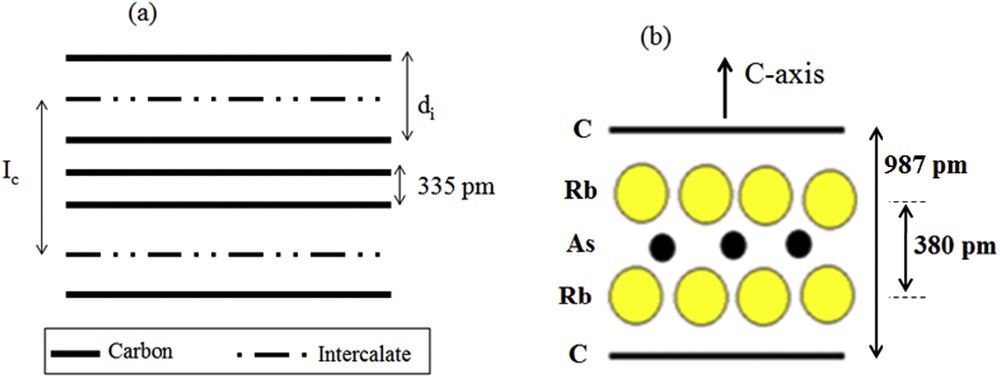
Schematic representation of (a) intercalation compound (GIC) (b) three-layer stacking sequence along the c-axis determined for the first stage α-graphite–rubidium–arsenic phase.
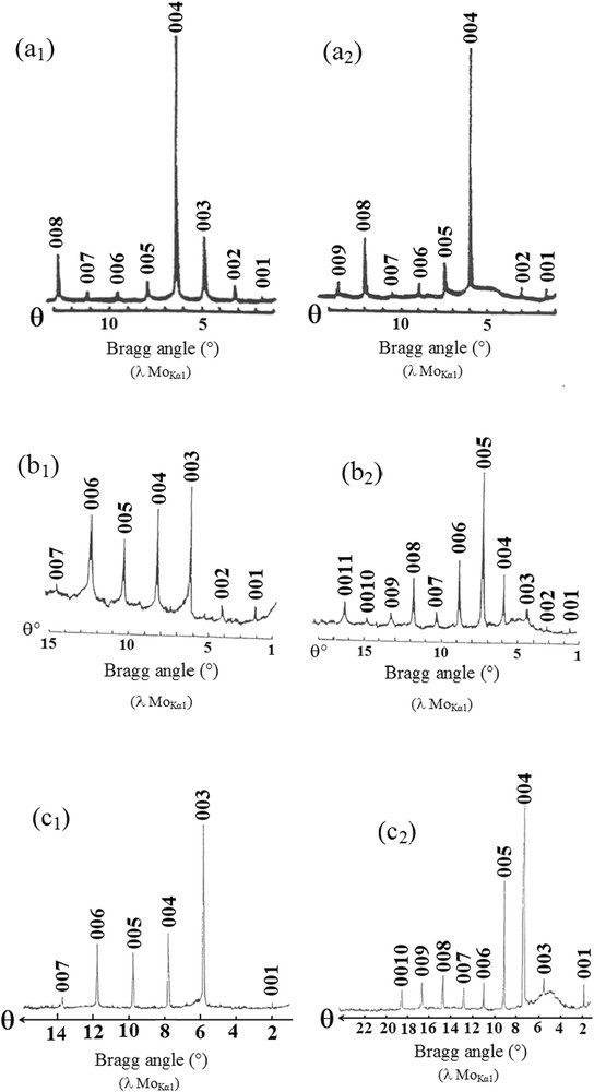
(00l) X-ray diffraction patterns of the heavy alkali metal-arsenic–graphite intercalation compounds (MoKα radiation): (a1) stage 2 α-G–K–As phase: IC = 1285 pm, (a2) stage 2 δ-G–K–As phase: IC = 1285 pm, (b1) stage 1 α-G–Rb–As phase: IC = 987 pm; (b2) stage 2 γ-G–Rb–As (c1) phase: IC = 1400 pm, stage 1 α-G–Cs–As phase: IC = 1110 pm, (c2) stage 2 γ-G–Cs–As phase: IC = 1445 pm.

SEM-EDS spectra of the phases: (a) α-G–Rb–As of stage1 (b) γ-G–Cs–As of stage1.
The major feature of these ternary GICs is the significant amount of the alloy intercalated into the host material. Structural analysis showed that the intercalated species are arranged as a multi-layer stacking model along the c-axis of graphite. An example of this configuration is illustrated in Fig. 2b. This three-layer stacking mode is the most common structure of this family of ternary compounds [ [24,25]]. Otherwise, the in-plane structural studies based on the analysis of the (hk0) reflection family have evidenced that the metallic sheets intercalated into these lamellar materials are perfectly ordered in parallel to the grapheme layers, by adopting various two-dimensional structures, with geometries that can commensurate or not, with respect to the graphite unit cell [26].
3 Physical properties
This paper focuses primarily on the most important results obtained from all the physical investigations, carried out on these ternary compounds. Electrical resistivity, dynamic magnetic susceptibility and Raman spectroscopy experiments have been performed on samples prepared as single phases. It is important to note that similar previous studies performed on related donor-graphite systems have shown that they are metallic parallel to the direction of graphene layers and highly anisotropic. It was also reported that some of them become superconducting at a low temperature [27,28].
3.1 Electrical resistivity
The graphite contains delocalized electrons (free electrons). These electrons can move through the graphite, carrying charge from place to place, and allowing it to conduct electricity. Electronically, graphite is considered as a semi-metal, which has a very low density of states at the Fermi level. Consequently, it contains a very low charge carrier concentration (10−4 per carbon atom). The relatively high value of its electrical conductivity σa (about 2.5 × 10⁴ Ω−1 cm−1) parallel to the direction of graphitic layers, could be explained by a very high mobility of charge carriers μa which is higher than 104 cm2 V−1. In contrast, the conductivity σc is only 10 Ω−1 cm−1 at 300 K along the crystallographic c-axis direction, i.e., perpendicular to the graphitic planes. Thus, graphite presents a strong anisotropy of conductivity and hence a high value of σa/σc ratio, which is in the order of 103 to 104 at 300 K. This value decreases when the temperature increases. The variation versus temperature of the planar conductivity can be explained by the decreased mobility of charge carriers when temperature increases. In fact, this decreased mobility is due to the electron–phonon interaction. The latter is more excited as temperature increases. During the intercalation process, an electronic exchange occurs between carbon layers and intercalated species. This charge transfer process results in an increase of the in-plane electrical conductivity. On the other hand, the electronic conduction mode along the c-axis direction is complex and its mechanisms aren't well understood yet [32,33].
3.1.1 Measurements
Electrical measurements are performed both parallel and perpendicular to the graphitic planes. Experiments were carried out on cylindrical graphite platelets having the following dimensions; diameter ϕ = 4 mm and a thickness ranging between 0.2 and 0.5 mm. The in-plane electrical resistivity measurements have been carried out using a conductive non-contact method developed at the laboratory [29]. This technique is very suitable for air-sensible sample studies, since transfer of any sample to the atmosphere is necessary. Indeed, the sample is placed in a sealed glass tube under vacuum, which allows for the performance of in situ measurements for electrical resistivity. On the other hand, the c-axis resistivity has been measured thanks to the four-point contact probe method, also developed at the laboratory.
3.1.2 Results
In Table 2, the parallel and perpendicular resistivity values of the studied phases are tabulated. These measurements were performed at three different temperatures: 295, 100 and 4.2 K. In the same table, the values of the electrical anisotropy A = ρc/ρa measured both at room temperature and at 4.2 K are also included. Measurements on the variation of the in-plane electrical resistivity with temperature ρa (T) were also carried out and the obtained results are shown in Fig. 4a. These measurements have been limited to two phases, which are the first stage β-G–KAs and the fourth stage β-G–Cs–As. This is due to the fact that the inductive contactless method does not allow for efficient measurements of the resistivity against temperature, on samples displaying values higher than 20 μΩ cm. The abusively high resistivity values are mainly due to the sample surface damage during the recovery. This method of measurement seems to be very sensitive to the extent of damage to the sample during its recovery inside a glovebox. The room temperature resistivity values are given in Table 2. Regarding c-axis resistivity measurements, the direct four-point probe contact method allowed performing all measurements against temperature. The typical curve obtained is shown in Fig. 5.
Electrical resistivity measurements of the G–M–As ternary phases (M = K, Rb, Cs) at temperatures: 295, 100 and 4.2 K.
| System | Stage and phase | ρa, μΩ cm | ρc, Ω cm | A = ρc/ρa | |||||
| 295 K | 100 K | THe | 295 K | 100 K | THe | 295 K | THe | ||
| G–K–As | 1 α | 27 ± 1 | 11 ± 0.5 | – | 0.29 | 0.25 | 0.25 | 1.1·104 | – |
| 1 β | 16 ± 1 | 4–4.5 | 2–2.1 | 0.18 | 0.073 | 0.043 | 1.1·104 | 2.1·104 | |
| 2 δ | 20–25 | – | 2–2.5 | 1.1 | 0.68 | 0.26 | 4.9·104 | 2.5·105 | |
| G–Rb–As | 2 γ | – | – | 5 ± 0.5 | 2.05 | 1.55 | 1.30 | – | 2.6·105 |
| G–Cs–As | 1 α | 35 ± 2 | – | 4–5 | 0.17 | 0.25 | 0.27 | 4.9·103 | 6·104 |
| 1 γ | 55 ± 10 | – | 4.5–5 | 0.12 | 0.058 | 0.043 | 2.2·103 | 8.6·103 | |
| 2 γ | 29 ± 1 | 15 ± 1 | 5 ± 0.8 | 2.15 | 1.97 | 1.82 | 7.4·104 | 3.6·105 |
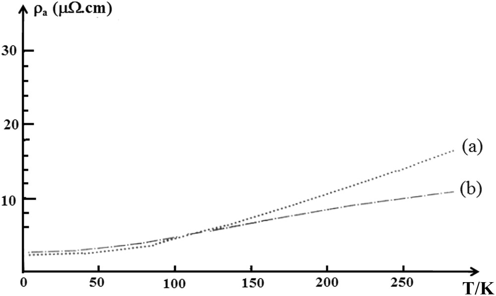
Temperature dependance of the in-plane resistivity of: (a) stage 1 β-G–K–As (b) stage 4 β-G–Cs–As ternary phases.

Temperature dependance of the c-axis resistivity of the stage 2 β-G–Rb–As ternary phase.
The ratio between the in-plane resistivity at 295 and 4.2 K is called the residual resistivity ratio (R.R.R. = ρa 295K/ρa 4.2K). It permits us to evaluate the density of structural defaults in the sample. Table 3 summarizes the calculated values for this parameter.
Residual resistivity ratio R.R.R. values of the G-M-As ternary phases (M = M, Rb, Cs).
| System and phase | 1 β K–As | 2 δ K–As | 1 α Cs–As | 1 γ Cs–As | 2 γ Cs–As |
| R.R.R | 8 | 10 | 8.5 | 10.8 | 5.8 |
3.2 Magnetic and optical properties
3.2.1 Dynamic magnetic susceptibility
The superconductivity is lacking in pristine graphite, but after charging the graphene planes with intercalation, its electronic properties change considerably and a superconducting behavior can appear. So, one of the remarkable physical properties of donor species-graphite intercalation compounds is that a number of them present superconducting behavior at a low temperature. Numerous studies in this field have shown that some binary and ternary donor-graphite intercalation compounds become superconductors at a very low temperature. KC8 GIC is a superconductor with transition temperatures below 0.14 K. Similarly, ternary compounds have proved to be superconductors as KHgC8 (TC = 1.90 K) [36], KTl1.5C4 (2.70 K) [37] or CsBi0.5C4 (4.05 K) compounds [38]. The Li3Ca2C6 GIC recently discovered is superconducting up to 11.15 K [39].
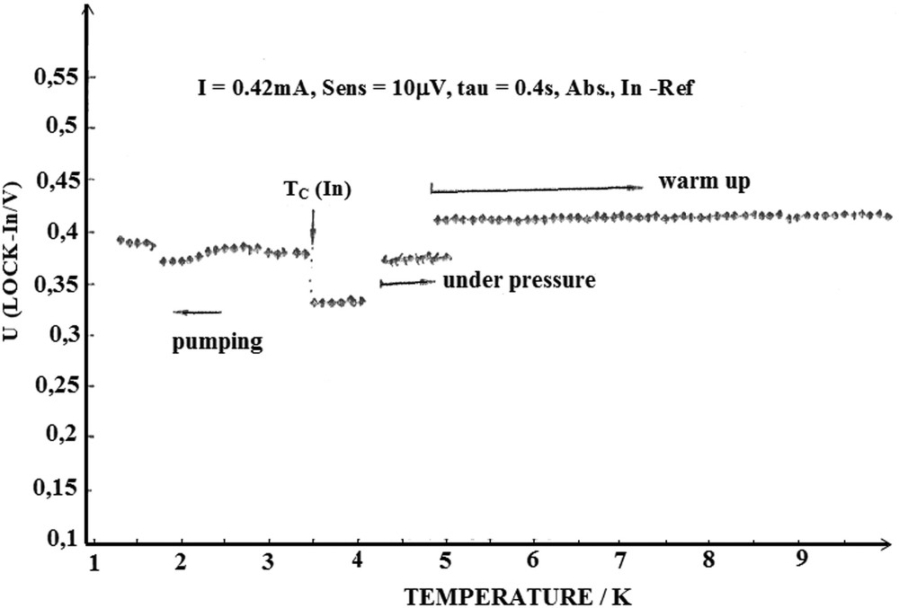
In order to examine the electronic behavior of our compounds, measurements of the dynamic magnetic susceptibility were carried out at a low temperature on some samples by I. Stang and K. Lüders from the University of Berlin in Germany. Four phases have been examined; stage 1 α G–Cs–As; stage 1 γ G–Cs–As; stage 2 β-G–Cs–As and stage 2 β G–Rb–As phases. The experimental method used is based on the measurement and monitoring of the magnetic susceptibility by cooling the sample from 10 to 1.3 K. Measurements were performed using the Lock-in signal detection method. This method consists of detecting the voltage (mV) measured out of phase with the driving current, by varying the AC magnetic field. The measured voltage value is directly linked to the magnetic susceptibility of the sample. In order to control the sensibility of the AC magnetic field, a small indium sample weighing 11.1 mg, used as the reference, was introduced within the coil containing the sample. The time constant amounts to 0.4 s, the frequency used is 67 Hz and the applied magnetic field amplitude is close to 40 mG.
Fig. 6 shows an example of the obtained curves. No superconducting temperature transition has been observed above 1.3 K over the four invested phases. Additional measurements on the untreated phases would be useful to conclude on the superconducting behavior of these compounds.

Representative Raman spectra of: (a) stage 1 α-G–K–As phase (sample 1) (b) stage 1 α-G–K–As phase (sample 2) (c) stage 1 β-G–K–As phase (d) stage 1 β phase β-G–Rb–As phase.
3.2.2 Optical properties
High Resolution-Raman Spectroscopy is a very useful tool to collect valuable information about the electronic structure of graphite intercalation compounds. For this purpose, Raman spectroscopy measurements have been undertaken on some bulk arsenic-heavy alkali metal based GICs synthesized at the laboratory. Raman spectra were recorded using a spectrophotometer equipped with a 514.5 nm argon laser working at 200 mW power (CREGU Center, Gs CNRS Nancy-France). The measurements were carried out at room temperature in the 1200–1650 cm−1 scanning range, with an exposure time of 5 s. Four of the obtained spectra are shown in Fig. 7. Note that samples were examined in air.
Temperature evolution of the dynamic magnetic susceptibility of the stage 1 γ-G–Cs–As phase from 295 to 1.3 K.
4 Discussion
4.1 Electrical conductivity and the conduction mechanisms
According to Table 2, some common findings might be formulated about the planar room temperature conductivity of these compounds;
- - It should be noted that two parallel experiments carried out on two samples of the same phase can yield significantly different results. This phenomenon might be due to the amount of the excess reactive alloy, which remains adhered to the sample surface. Unavoidably, it causes fluctuations in their treatment during sample recovery in the glovebox. It is quite normal that variations in the surface treatment will affect the sensitivity of the electrical measurement.
- - It is well known that among all the parameters controlling the in-plane conductivity of the graphite intercalation materials, the determining factor is the charge transfer established between the intercalate and carbon layers. No direct measurement of this parameter has been performed on these compounds, and therefore no conclusion could be made regarding its contribution to the in-plane resistivity. However, we can suppose that this transfer factor would be lower than that encountered with the related binary graphite-alkali metal compounds, formulated as MC8, where M could be K, Rb, Cs or Li, [30]. As mentioned above, the arsenic element present in the middle of the multilayered intercalated sheet, due to its pronounced electro-negativity, could capture a fraction of the alkali's electron (donor atom). This leads to a drop in the electronic exchange rate between the alkali metal and carbon atoms of the neighboring graphite planes, causing thereby a decrease in conductivity. As shown in Fig. 4a, the curve shape of the in-plane resistivity variation against temperature is composed of a residual resistivity observed at a lower temperature, which is directly related to the intrinsic default density in the sample. Additionally, a second component, represented by a quasi-linear portion of the curve, rises with the increase of temperature (dρa/dT > 0). This second component is due to the phonon-electron interaction mode previously observed for similar compounds.
The examination of the planar resistivity data shown in Table 2 makes it possible to deduce that all phases have relatively low in-plane conductivity, except for the stage 4 β-graphite–cesium–arsenic and the stage 1 β-graphite–potassium–arsenic phases, which are close to the planar conductivity of the binary alkali-graphite compounds [31].
In regards to the c-axis electrical conductivity, they are the first stage phases, which are found to be the best conductors; particularly the phases β-G–K–As and γ-G–Cs–As. Both phases are of stage 1, i.e., the same phases that exhibit a low basal plane conductivity. On the other hand, α-type phases and those with high stage (2 and 4), have moderate electrical conductivity values along the c-axis. The electronic transport mechanisms through the c-axis, involved in these lamellar materials, have been the subject of research by a number of authors [32–35]. Several electronic conduction models have been suggested, but they do not satisfactorily explain the observed phenomena. This is due to the complexity of this task, undoubtedly linked to a great number of physical and chemical parameters, which should be taken into consideration to understand the involved electronic transport modes. Among them, it is possible to mention the c-axis carbon layer stacking mode; in-plane arrangement of the atomic intercalated sheets (liquid state, crystalline state, commensurate or no-commensurate with the graphite unit cell...); coexistence of more than one phase in the same compound; existence of agglomerates and domains within the crystal lattice, etc. [35]. In the light of this discussion, it can be deduced that these graphite-based materials present a c-axis resistivity that increases with temperature. In addition, the ρc (T) plots appear to be linear with a “metallic-like” starting from room temperature up to 4.2 K. However, the “metallic” term is just indicative because it couldn't qualify the self-nature of the c-axis conductivity, whose values are largely outside the metallic range, in contrast to the planar resistivity. A typical example of c-axis resistivity evolution against temperature is displayed in Fig. 4b. This wide gap conductivity in both directions leads to a large anisotropy: A = ρc/ρa. The values at room and low temperatures (295 and 4.2 K) are shown in Table 2. As can be seen, it can reach values more than 104 Ω−1 cm−1 at room temperature in the case of the stage 2 γ-Cs–As phase, and even more at low temperatures (>105 Ω−1 cm−1). This value could be compared to 1.8 × 10⁵ Ω−1 cm−1, observed for the stage-4 K–Bi based graphite intercalation compound. Compared to the binary alkali metal-graphite compounds, they are more than 102 times higher and they should be rather comparable to the graphite-acceptor compounds. The residual resistivity ratio, defined as R.R.R. = ρ295K/ρ4.2K, is calculated and the values of this quantity are listed in Table 3. They are rather small and are located between 8 and 11. They are in the same order of magnitude greater than those observed for the homologous intercalated ternary compounds, commonly comprised between 6 and 12. Typical residual values for the derivative binary GICs, in comparison, are 200 and 300 for KC8 and RbC8 compounds, respectively. R.R.R is assumed to be a significant indicative parameter of the density of defaults present in the GIC materials. The smaller the residual value, the greater the density defaults of the material. In contrast, the higher the residual value, the better the structural quality of the samples. Thus, the default density in GIC compounds might be more important for the thick multi-layered sheet intercalated compounds than for the mono-layered ones, like the alkali-based graphite GICs. This explains the low R.R.R. values observed for the poly-layered graphite intercalation compounds.
4.2 Raman investigation and chemical stability
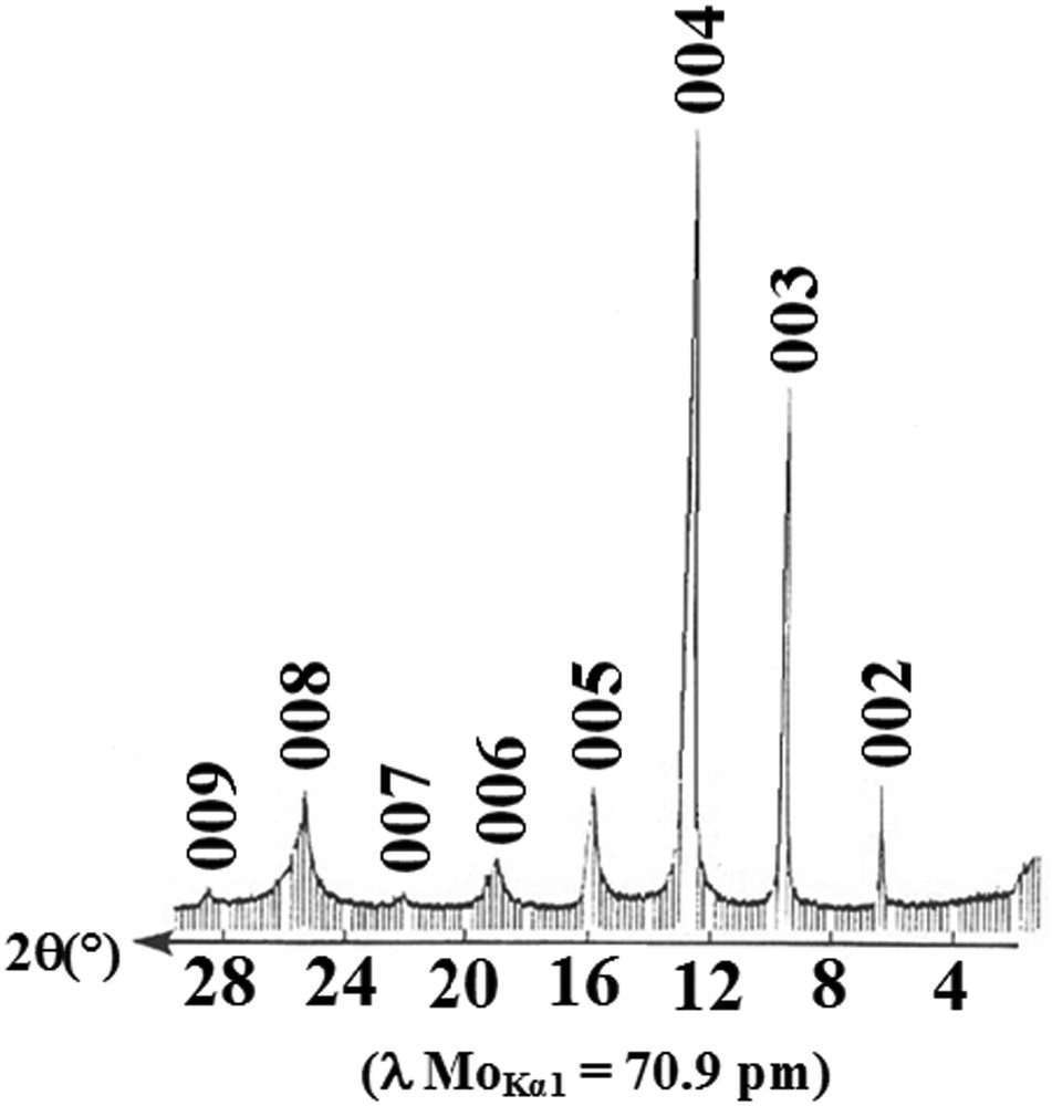
Examination of Raman spectra displayed in Fig. 6 shows that they present a broadened peak centered around 1600 cm−1. This line is assigned to the E2g2 vibration mode of the carbon plane surrounded on both the sides by intercalate of stage 1, and by intercalate on one side and a graphitic layer on the other side for stage 2 compounds [41]. The appearance of this line confirmed the existence of intercalate in the graphite interlayer gallery. Similar shaped spectra have been reported in previous studies on homologous binary and ternary compounds [40,41]. For some first stage samples less stable in air, the G-broadened line splits into two components, accompanied by a second band located at 1581.2 cm−1 or at 1578.1 cm−1, clearly observed in Fig. 6a and b. This splitting band could be attributed to a specific intermediate product between a first stage and de-intercalated galleries, giving rise to uncharged inner graphitic layers [42]. But in general, we can say that these compounds (of stage 1 and 2) exhibit Raman spectra, which are characterized by the presence of a unique broadened line focused at around 1600 cm−1. This indicates that the structure of the sample was retained and is chemically stable as it is demonstrated in Fig. 8, related to the (00l) X-ray pattern of a second stage compound recorded after six months of its exposure to air. This means that most of the heavy alkali-metal atoms remained in the graphite interlayer spaces. On the other hand, the G-line position of the spectra is energy up-shifted by electron doping from 1582 cm−1 in pure graphite to ∼1600 cm−1. In fact, researchers have shown that the E2g2 bounding layer modes up-shifted (downshifted) in frequency by 10–30 cm−1, for the acceptor (donor) type GICs relative to 1582 cm−1 line of pure graphite. These shifts were attributed to the contraction (acceptor GICs) and expansion (donor GICs) of the intra-layer covalent CC bonds induced by the charge transfer. Furthermore, it is remarkable to note that the G-line centered around 1600 cm−1 has substantially the same vibrational frequency and a similar shape to that observed with the acceptor species LiC6 and EuC6 compounds [43]. Raman spectroscopy investigation has always been considered as a useful tool to probe the electronic charge transfer involved in these materials [44–46]. This up-shift of the single E2g2 Raman peak, ascribed to the in-plane atomic carbon vibrations, is definitely linked to the charge transfer exchanged between intercalate and bonding graphene layers. This charge transfer seems to be important as it was reported by Lüders et al. [47]. The authors revealed, based on 133Cs-NMR studies, that the degree of ionization of Cs-alkali-metal in the stage 1 α-Cs–As-phase is larger than in the Cs–Bi-GIC. Finally, it should be noted that many factors have to be taken into consideration to correctly extract the Raman response of a GIC sample, such as intrinsic disorder of the crystal, laser induced heating of the sample and air intrusion, which strongly affect the Raman response in the GIC.
(00l) X-ray diffraction pattern of the stage-2 α graphite–potassium–arsenic after 2 months of exposure in air.
5 Conclusions
Heavy alkali metal-arsenic alloys easily intercalate into graphitic galleries leading to a new family of intercalation compounds. Numerous phases have been synthesized according to temperature, composition and duration time of the reaction. The in-plane resistivity measurements carried out on these phases revealed that the obtained values at ambient temperature ranged within the metallic field. Along the c-axis, the resistivity is very high and not metallic-like. These opposite values result in a high anisotropic resistivity (A = ρc/ρa) and a value of an order of magnitude more than105 has been recorded at 4.2 K temperature. Both ρa(T) and ρc(T) curves of the evolution of resistivity according to temperature were measured. At low temperature, a residual resistivity subsists and it is directly related to the structural default density present within the bulk sample. When the temperature increases, the resistivity shows a quasi-linear increase in proportion to temperature. This is due to the phonon-electron interaction process.
Dynamic magnetic susceptibility measurements showed no superconducting transition up to 1.3 K. High Resolution Raman spectroscopy analyses revealed a good chemical stability of these phases at the microscopic scale, as demonstrated by the presence of a stable broadened G-band peak located at 1600 cm−1, characteristic of a graphite intercalated compound (GIC). An up-shift of this line, with respect to the intra-layer grapheme frequency in pure graphite was observed. It is reliable to the charge transfer between the intercalated species and bonding carbon layers. This electronic behavior is intrinsically related to the significant ionization degree of the alkali metal, as it was previously reported during 133Cs NMR investigation.