

1 Introduction
The severe environmental regulations concerning the reduction of sulfur content in diesel oil demand a drastic efficiency of the hydrodesulfurization (HDS) of petroleum feedstock, which is a catalytic process most generally performed on CoMo/Al2O3 catalysts. The active phase of these catalysts is the so-called CoMoS phase that consists of well dispersed MoS2 nanocrystallites decorated with Co promotor atoms located at the edges and corners of the MoS2 slabs [1]. This active phase is obtained by sulfiding an oxidic precursor, generally prepared by incipient wetness impregnation of an alumina support with an aqueous solution containing the elements to be deposited (Co and Mo), followed by a drying and a calcination step. New methods of preparation of the oxidic precursors have been developed in order to improve catalytic performance. Among them the use of Keggin or Anderson based heteropolyanions was proposed several years ago to prepare impregnating solutions instead of the classical ammonium heptamolybdate precursor [2,3]. Improvements have also been obtained through the addition of organic agents to the impregnating solution prepared with [4,5] or without [6] heteropolyanions. More recently the modification of dried or calcined oxidic precursors by organic molecules was shown to improve HDS catalytic performances [7–10]. Whatever the approach, various organic agents that have been used can be divided in two families: the chelating agents allowing complexation with metallic ions and the non-chelating agents. Among the chelating molecules, EDTA (ethylenediaminetetraacetic acid) [11], En (ethylenediamine) [12,13], CyDTA (cyclohexanediaminetetraacetic acid), NTA (nitrilotriacetic acid), TA (tartaric acid) [5] or saccharose [14] were considered. In our laboratory TGA (thioglycolic acid) [7,8], also described as a sulfiding agent [15], was used to impregnate a commercial CoMo/Al2O3 oxidic precursor. Recently due to its low cost and availability, citric acid has attracted much attention for the preparation of fresh catalysts [4,6,11]. Through the formation of Mo and/or Co complexes with the chelating agents, the improved HDS catalytic activities have been ascribed to (i) a decrease of the interaction between metals and the support [16–21] and/or to a lower formation of cobalt aluminate [2], (ii) an improvement of the Mo and/or Co dispersion [2,12,13,22–26], and (iii) the modification of the sulfidation of Co and Mo atoms (delay of Co sulfidation) [7,8,27–35].
Researchers have also developed modifications with non-complexing agents. Among them the glycol-type agents have been largely employed [9,20,21,36]. In these cases the beneficial effect cannot be related to metal complexation. According to Nicosia and Prins [21] introduction of TEG (triethyleneglycol) into the impregnating solution containing phosphorus restrains interaction between metals and the support and facilitates Co interaction with phosphomolybdate species in solution while according to Iwamoto et al. [25,26] the role of PEG (polyethyleneglycol) with a high molecular weight was to prevent Co and Mo aggregation facilitating their dispersion on the support surface. Gonzalez-Cortes et al. [37] have proposed a “urea-organic matrix” method with addition of urea to the impregnating solution to prepare modified HDS CoMo catalysts in order to improve the dispersion of Co and Mo species and to increase the MoS2 slab stacking for better HDS performance.
Recently we have shown that the use of the non-complexing 1,5-pentanediol for the modification of CoMoP/Al2O3 oxidic precursors led to a drastic increase of the performance in SRGO HDS [10]. To understand the role of this type of agent, we investigate here its effect on the gas phase sulfidation and on thiophene HDS performance. A detailed characterization of the genesis of the active phase monitored by XPS together with thermogravimetric analysis allows us to describe the exact role of the pentanediol modifying molecule.
2 Experimental
2.1 Preparation of the oxidic precursor
The CoMo/Al2O3 solid used in this work is a commercial catalyst containing 17.3 wt% of MoO3, 3.5 wt% of CoO and 0.08 wt% of P. This oxidic precursor will be denoted hereafter by CoMoRef. Its presents a surface area of 260 m2 and a water pore volume of 0.9 cm3 per g of catalyst.
2.2 Preparation of the modified oxidic precursors
The CoMoRef was pore volume impregnated with an aqueous solution containing the desired amount of 1,5-pentanediol (C5diol) to have a C5diol/Mo molar ratio equal to 1. After 2 h of ageing, the modified solid was dried at 80 °C under N2 for 15 h. The CoMo modified solid is denoted by CoMo1C5diol.
2.3 Sulfided catalysts
For characterizations the oxidic precursors were sulfided for 3 h (otherwise specified) at temperatures ranging from 50 to 350 °C. Prior to sulfidation no additional pretreatment, neither drying nor calcination, was performed on the CoMoRef or CoMo1C5diol solids. The sulfidation took place at atmospheric pressure with a flow (100 mL/min) of a H2/H2S (90/10) mixture in a glass reactor. The sulfidation temperature ramp was 6 °C min−1. After sulfidation the reactor was closed and immediately cooled down at room temperature. It was then placed in a glove box under argon in order to avoid any re-oxidation of the solids during the sampling for XPS and HRTEM analyses.
2.4 Catalytic activity
Catalytic activity in thiophene HDS was measured at atmospheric pressure in a flow-bed reactor packed with 200 mg of catalyst. The reactor is designed to work under differential conditions. The catalysts were firstly sulfided at 350 °C for 3 h under a flow (100 mL min−1) of a H2S/H2 (10/90) mixture in the catalytic reactor. Then the temperature was cooled down to 270 °C for the evaluation of thiophene HDS conversion. After purification by vacuum distillation thiophene was introduced into the reactor at constant pressure (50 Torr) in a flow of purified hydrogen (10 mL min−1). The reaction products (butane and butene) were analyzed by gas chromatography. For the conversion values measured in this work, the HDS rate can be calculated by r = α Dthio/m, where Dthio is the flow of thiophene, m is the mass of the catalyst, and α is the thiophene conversion [38]. As the density of the different catalysts is not constant due to the addition of C5diol, the reaction rate is expressed per gram of catalyst corrected by the loss of ignition.
2.5 Characterizations
- - Raman spectroscopy
The Raman spectra of the samples were recorded at room temperature using a Raman microprobe (Infinity from Jobin-Yvon) equipped with a photodiode array detector. The exciting laser source was the 532 nm line of a Nd-YAG laser with a beam power of 0.23 mW at the focal point. The wavenumber accuracy was 2 cm−1. A filter was used to decrease the power of the laser beam in order to avoid an evolution of the samples during analysis. For each sample, several particles were analyzed to check the homogeneity of the solid.
- - UV-Visible
UV-Visible spectra of solutions or solids were recorded using a PerkinElmer Lambda 650 spectrometer equipped with an integration sphere. The wavenumber accuracy was 1 nm.
- - Thermogravimetric analysis
Thermogravimetric study of the sulfidation under a H2/H2S atmosphere was performed using a thermogravimetric apparatus (Rubotherm) designed for measurements under corrosive/dangerous gases such as H2S and coupled with a rapid chromatograph (Agilent 3000). This analysis permits, during the sulfidation, a correlation between the evolution of the sample mass and the quantity and nature of outlet gases after reaction of the catalysts with the H2/H2S mixture. The solid was heated up to 350 °C with a ramp of 120 °C h−1 under a H2/H2S (90/10) mixture gas (100 mL min−1). For the analysis of CoMoRef, 2.000 g of oxidic precursor were introduced into the apparatus, which correspond to 9.5.10−4 mol of Co and 2.4.10−3 mol of Mo. For the analysis of CoMo1C5diol, 2.290 g of modified oxidic precursor were used in order to introduce the same amount of Mo and Co (2.290 g of CoMo1C5diol contain 0.250 g of C5diol, 2.000 g of CoMoRef and 0.040 g of remaining H2O that was not eliminated during the drying step following the impregnation with the modifying agent aqueous solution).
- - RPE
The catalyst sulfidation was in situ studied by RPE. The glass cell in which the catalysts were analyzed was designed to be connected to the sulfidation apparatus. The solid was heated from room temperature to 300 °C with a ramp of 120 °C h−1 under a H2/H2S (90/10) mixture gas with a flow of 100 mL min−1. The spectra were recorded every 10 degrees using a Varian E9 spectrometer that delivers a homogeneous magnetic field between 0 and 20,000 Gauss. The signal of the sample is monitored at 100 kHz.
- - X-ray photoelectron spectroscopy (XPS)
The catalyst was characterized by XPS before and after modification with 1,5-pentanediol and at different steps of the gas phase activation. For the sulfided samples, XPS sampling was performed under an argon atmosphere in a glove box. The powdered samples were pressed on an indium foil attached to the sample holder, which was introduced directly into the XPS spectrometer thanks to the connection of the glove box to the XPS transfer chamber.
XPS spectra were recorded with the VG ESCALAB 220 XL spectrometer equipped with a monochromatic Al Kα (E = 1486.6 eV) X-ray source. The spectra were collected with a pass energy of 30 eV using the electromagnetic lens mode low-energy electron flood gun for charge compensation effects. The binding energies (BEs) of Mo3d, Co2p, C1s and S2p (sulfided samples) were determined by computer fitting of the measured spectra and referred to the Al2p photopeak of the support at 74.6 eV. The BEs were estimated within ±0.2 eV. The surface atomic ratios IMo3d/IAl2p and ICo2p/IAl2p were calculated using the CASA software after subtracting the nonlinear Shirley background and the contribution of the S2s signal to the Mo3d signals (sulfided samples).
The Mo3d and Co2p spectra were decomposed using an interactive least-squares program and the fitting peaks of the experimental curves were defined thanks to a combination of Gaussian (70%) and Lorentzian (30%) distributions. These decompositions, based on the peak areas relative to each chemical species present on the surface of the solid, allow us to estimate the percentage of Mo atoms forming the MoS2 slabs (Mo sulfidation degree) and the percentage of Co atoms implied in the CoMoS phase and Co9S8 bulk sulfide.
The Mo3d spectra were decomposed into the three well-known contributions respectively attributed to MoVI oxide (Mo3d5/2 BE = 233.0 eV), MoVoxysulfide (Mo3d5/2 BE = 230.5 eV) and MoIV (MoS2) (Mo3d5/2 BE = 228.8 eV) [39] (Fig. 1A). The decompositions of the Mo3d spectra were performed simulating each contribution with two peaks corresponding to the Mo3d5/2 and Mo3d3/2 core levels and taking into account that the binding energy difference BE (Mo3d5/2)-BE (Mo3d3/2) is equal to 3.15 eV, the Mo3d5/2/Mo3d3/2 peak area ratio being equal to 1.5 and the full width at half maximum (FWHM) of the Mo3d5/2 and Mo3d3/2 peaks being almost the same [39–43]. The S2s peaks, which contribute to the total envelope of the spectra of Mo3d, were simulated (with one peak for each sulfur type species i.e., S2− and ) by taking as reference the corresponding S2p peaks with respect to the following criterion: BE(S2s)–BE(S2p) = 64 eV.
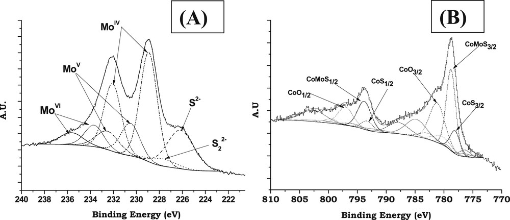
Typical decomposition of XPS spectra after sulfidation (H2/H2S, 90/10) at 350 °C for 3 h: (A) Mo3d; (B) Co2p.
Due to the complexity of the Co2p spectrum (multiplet effect and satellite structures) [40] the methodology implemented consisted in isolating successively the contributions of each Co-based chemical species. Each contribution has been simulated with several peaks corresponding to the Co2p3/2 (main peak + satellite structure) and Co2p1/2 (main peak + satellite structure) core levels. For each contribution the spectral parameters (BE differences, intensity ratios and FWHM ratios) of these peaks are interdependent in all the decompositions. This permits to decompose the spectra by varying only the global intensity of each contribution to obtain the relative amount of each species. Fig. 1B shows an example of decomposition of the Co2p spectrum of a sulfided catalyst. For each spectrum three contributions were used considering only the presence of three states for Co atoms, i.e., Co2+ in the oxide state, CoMoS phase and Co9S8 bulk sulfide as will be discussed hereafter.
The absence of any signal at 169.0 eV (characteristic of sulfates) indicates that no re-oxidation of the sulfided catalysts occurred during the transfer of the solid from the sulfiding reactor to the XPS machine.
- - High Resolution Transmission electron microscopy (HRTEM)
High Resolution Transmission electron microscopy was performed on a TECNAI TEM (200 kV). Freshly sulfided samples were ground under an inert atmosphere and dispersed in heptane. The suspension was collected on a microscope grid covered with a thin lacey carbon film. For statistical analysis, more than 20 photographs were taken, which enabled us to measure about 2000 slabs for each sample. Statistical analysis of each photograph was done by measuring the length (L) and stacking (N) of the MoS2 slabs.
3 Results
3.1 Reactivity
Thiophene HDS rates (per g of catalyst corrected by the loss of ignition) obtained for the CoMoRef and CoMo1C5diol catalysts are reported in Table 1. The modification of the conventional oxidic precursor by 1,5-pentanediol induces an increase in the catalytic performance in the HDS of thiophene. Physico-chemical characterizations of this modified oxidic precursor have been performed at each step of the genesis of the active catalyst in order to understand the exact role of this agent.
Catalytic performance in thiophene HDS for the studied solids.
| Catalysts | Thiophene HDS rate (mol s−1 g−1) |
| CoMoRef | 4.0.10−8 |
| CoMo1C5diol | 5.6.10−8 |
3.2 Characterization of oxidic precursors before and after modification with C5diol
Various physical techniques have been used to characterize the modified oxidic precursor to evidence the changes occurring upon impregnation with C5diol.
3.2.1 Raman spectroscopy
Fig. 2 shows the Raman spectra of CoMoRef and CoMo1C5diol catalysts in the 200–1600 cm−1 range. For comparison the spectrum of an aqueous 1,5-pentanediol solution is also presented. The spectrum of CoMoRef does not exhibit the features of bulk oxides such as MoO3 or CoMoO4 while it shows lines at 360, 560 and 950 cm−1 characteristic of the presence of well dispersed polymolybdate species [44], considered as consisting of well dispersed AlMo6O24H63− entities [2]. The spectrum of the modified solid is exactly the same as that of the starting oxidic precursor, which suggests that no modification of the nature of the oxomolybdate phase occurs upon impregnation with 1,5-pentanediol. Some Raman lines in the 1300–1500 cm−1 range are also observed, which confirms that pentanediol is present in the porosity of the modified oxidic precursor.
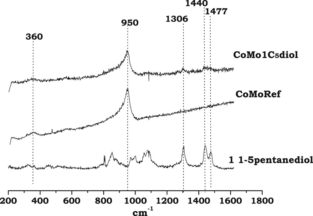
Raman spectra of CoMoRef and CoMo1C5diol solids compared to that of 1,5-pentanediol in the liquid state.
3.2.2 UV spectroscopy
Fig. 3A,B,C present the UV spectra of Co based solutions and CoMo based solids.
- - Mo entities: The spectrum of CoMoRef (Fig. 3B) exhibits a broad dissymmetric band with a maximum at about 270 nm, which evidences the presence of polymolybdate entities [45]. No modification is observed upon addition of C5diol. This is in agreement with the aforementioned Raman study that does not show any change of the Raman spectrum upon impregnation with the organic agent.
- - Co entities: Upon addition of C5diol to a Co sulfate aqueous solution no modification of the spectrum is observed as shown in Fig. 3A. The observed doublet of bands at 480 and 510 nm is due to the Co(H2O)62+ complexes present in aqueous solution [12]. Thus no complexation of the Co2+ by the organic agent is evidenced. Regarding solids, the spectrum of the reference solid CoMoRef (Fig. 3C) exhibits a triplet of bands at 537, 580 and 635 nm usually observed for Co(Mo) oxidic precursors and that corresponds to Co2+ ions in tetrahedral sites of the alumina lattice (Cotet-Al) [12,46]. No bulk oxides such as Co3O4 (broad bands at 400 and 750 nm) and CoMoO4 (broad band at 525 nm) are evidenced [12]. It is well admitted that Co2+ ions can also be in octahedral environment (Cooct-Al) in the alumina lattice. Indeed such Cooct-Al entities are suspected to be located near the alumina surface in interaction with Mo entities and to be the precursors of the Co atoms participating in the formation of the CoMoS phase after sulfidation [47] while the Cotet-Al ions that are considered to be deep in the support are known to be less sulfidable [48]. To directly compare the relative amounts of Cooct-Al and Cotet-Al species in our two samples, the UV-Visible spectra were normalized to obtain similar intensities of the band at 425 nm (characteristic of Cooct-Al [49,50]). Upon modification with C5diol the relative intensity of the Cotet-Al characteristic bands slightly decreases, meaning that the relative amount of Cotet-Al species is decreased by addition of this organic agent. This suggests that the modification by this organic agent induces an extraction of some Co ions in tetrahedral sites to the benefit of Cooct-Al species.
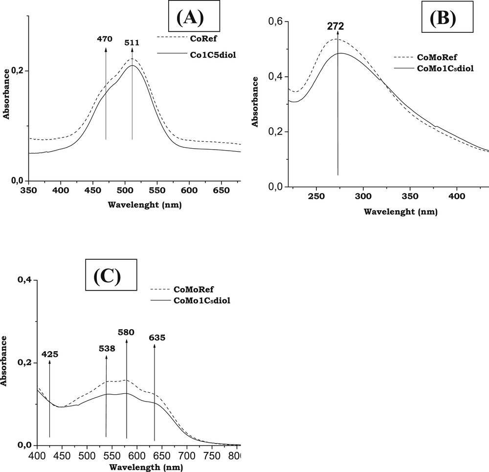
UV spectra: (A) Co sulfate and Co sulfate + C5diol aqueous solutions (350–700 nm range); (B) CoMoRef and CoMo1C5diol solids at low wavenumbers (200–460 nm range); and (C) CoMoRef and CoMo1C5diol solids at high wavenumbers (400–800 nm range).
3.2.3 XPS
Fig. 4A,B respectively show the XPS spectra of Mo3d and Co2p core levels of CoMoRef and CoMo1C5diol solids while Table 2 presents the IMo3d/IAl2p and ICo2p/IAl2p that are characteristic of the dispersion of the Mo and Co entities.
- - Binding Energies: The Mo3d spectrum of the reference oxidic precursor exhibits a Mo3d5/2 photopeak with an apparent binding energy (BE) equal to 233.0 eV, which is characteristic of MoVI in oxide environment while the Co2p spectrum shows the features of cobalt in oxide environment with the Co2p3/2 peak at 781.8 eV and a shake-up satellite at higher binding energy. The introduction of C5diol does not induce any clear change in these XPS spectra, which confirms the Raman and UV results that evidence no change in the chemical environment of Mo and Co atoms.
- - Dispersion of Mo and Co: Table 2 presents the IMo3d/IAl2p and ICo2p/IAl2p intensity ratios for the CoMoRef and CoMo1C5diol catalysts before and after sulfidation. The intensity ratios IMo3d/IAl2p are not clearly affected upon modification. Thus the Mo dispersion is not improved by the organic agent, in agreement with the similarity of the CoMoRef and CoMo1C5diol Raman spectra. After sulfidation no difference is observed between the two catalysts. Regarding Co, at the oxidic state a slight increase in the ICo2p/IAl2p ratio is observed. This difference could be related to the decrease in the relative amount of Cotet-Al species, as shown by UV-Visible, which contributes to increase the quantity of Cooct-Al species. Indeed the latter are supposed to be located near the surface of the support while the former are supposed to be located below the alumina surface [47,48]. However, after sulfidation the ICo2p/IAl2p ratios are exactly the same, which means that the amount of Co detected by XPS is the same for the two solids.
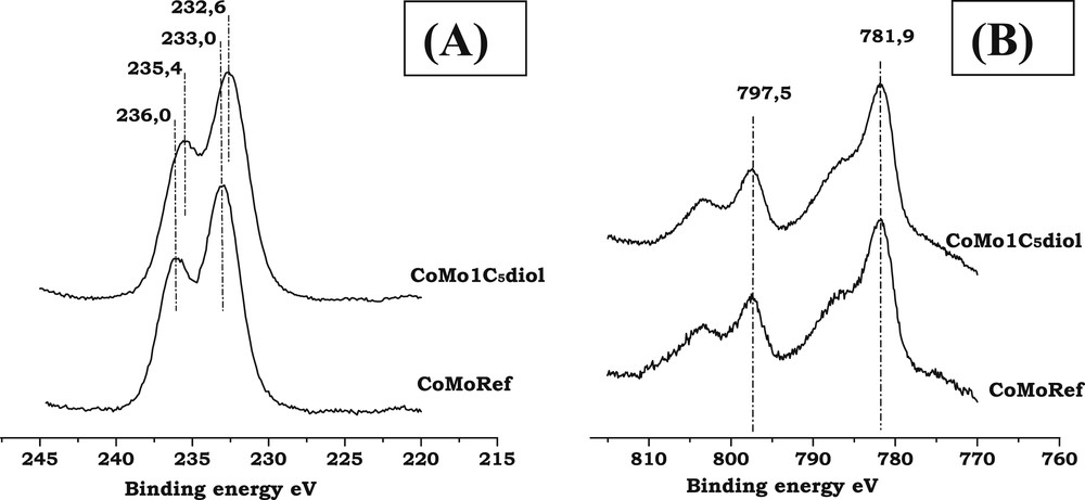
XPS spectra of CoMoRef and CoMo1C5diol: (A) Mo3d; (B) Co2p.
Dispersion of Mo and Co for CoMoRef and CoMo1C5diol solids as determined by XPS.
| Samples | IMo3d/IAl2p | ICo2p/IAl2p |
| CoMoRef | 1.60 | 0.92 |
| CoMo1C5diol | 1.70 | 1.13 |
| Sulfided CoMoRef | 1.40 | 1.02 |
| Sulfided CoMo1C5diol | 1.40 | 1.00 |
3.3 Characterization of the catalysts during the gas phase activation
3.3.1 Thermogravimetric analysis under sulfiding conditions
3.3.1.1 CoMoRef
Fig. 5 shows the TGA curve of the CoMoRef weight upon sulfidation as well as the evolution of the relative amounts of H2 and H2S at the reactor outlet. Four zones that correspond to specific evolutions of the catalyst weight and of the amount of H2S can be evidenced:
- - From 20 to 70 °C (zone 1) the catalyst weight and the amount of outcoming H2S increase with the increase in temperature. The outcoming H2S is lower than the incoming one, which is in agreement with the weight increase that is correlated to the H2S uptake.
- - From 70 to 100 °C (zone 2) the catalyst weight decreases while the amount of outcoming H2S is lower than the amount of incoming H2S.
- - From 100 to 130 °C (zone 3) the catalyst weight still decreases but the amount of outcoming H2S is higher than the amount of incoming one, which indicates that sulfur is eliminated from the solid in this temperature range.
- - From 130 to 300 °C (zone 4) the weight of the catalysts still decreases while the amounts of incoming and outcoming H2S are similar. After gas phase activation a global weight increase equal to 0.025 g is observed.
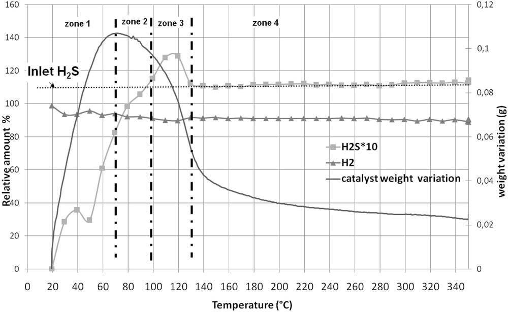
Thermogravimetric analysis of CoMoRef under H2/H2S (89/11): evolution of the catalyst weight and of the relative amounts of H2 and H2S at the outlet of the reactor.
It is thus possible to estimate the amount of H2S that is consumed (or released) by the solid during sulfidation and to correlate it to the variation of weight in the solid. Table 3 presents the results of this quantification for each zone of Fig. 5. It is important to note that H2O is detected all along the sulfidation from room temperature up to 300 °C (not represented on Fig. 5).
- - From 20 to 70 °C (zone 1), 7.3.10−3 mol of H2S are consumed by the catalyst. Taking into account that 2.000 g of catalyst are introduced into the thermogravimetric apparatus (corresponding to 3.35.10−3 mol of Co + Mo), only 5.65.10−3 mol of S should be necessary to quantitatively form MoS2 and Co9S8. This indicates that some H2S has been consumed on the solid or is adsorbed. However, if the entire H2S is adsorbed, it should correspond to a theoretical weight gain of 0.234 g on the solid while the experimental weight gain is only of 0.107 g in this temperature range. That means that part of the consumed H2S is used for sulfidation of the solid inducing a loss of gaseous water due to O–S exchanges. These results are in accordance with those found by Échard et al. [51], who showed that at low temperatures H2S is consumed in large excess, corresponding to its adsorption on the support and on the active metals and its reaction with the catalyst for sulfidation. Nevertheless we can also note that the H2S consumption is consistent with the formation of MoS3. Indeed, 7.2.10−3 mol of H2S are necessary to sulfidize the entire Mo into MoS3. This species was proposed as a sulfidation intermediate by several authors. However it was, in all cases, observed at higher temperatures than 70 °C. Payen et al. [52] observed this entity after sulfidation at 267 °C for 1 h of a Mo/Al2O3 dehydrated oxidic precursor while Prins et al. [53] evidenced it during the sulfidation of a CoMo/Al2O3 oxidic precursor between 108 and 255 °C. Moreover they did not evidence such a sulfidation intermediate with a CoMoP solid.
- - From 70 °C to 100 °C (zone 2), the solid weight decreases whereas 1.3.10−3 mol of H2S are consumed. This decrease is mainly due to H2O elimination as shown by chromatographic analysis of the gaseous mixture at the outlet of the reactor. This water comes from the sulfidation of the solid and the decrease in the weight of the solid is in accordance with the hypotheses proposed by Echard et al. [51]. Studying the sulfidation of a CoMo catalyst with a H2/H2S mixture under pressure (about 42 bar) these authors proposed that in this temperature range the sulfur involved in the transformation of the oxidic phase into sulfidic ones comes from previously adsorbed H2S and not from H2S coming from the gas phase. Indeed, if this sulfur comes only from the gas phase, the weight of the solid should increase due to the intrinsic difference of weight between S and O. Another possibility to explain the decrease in the weight is that the water formed during sulfidation between room temperature and 70 °C desorbs at higher temperatures.
- - From 100 to 130 °C (zone 3), about 10−3 mol H2S is released from the catalyst, which induces a decrease in the solid weight, the latter being also due to a loss of water as shown by the GC analysis. Such a loss of weight was also observed by Echard et al. [51] who assigned it to the desorption of the H2S adsorbed at lower temperatures.
- - From 130 to 300 °C (zone 4), the continuous decrease in the catalyst weight is mainly related to the loss of water as detected by chromatography. Moreover it is very interesting to see that the amounts of H2S at the inlet and outlet of the reactor are similar in this temperature range, which allows us to suggest that if the sulfidation of the solid continues after 130 °C, which is very likely as we will see after, the H2S used for this transformation comes mainly from previously adsorbed H2S. This hypothesis is different from the one made by Echard et al. [51] who proposed that the gas phase containing H2S contributes largely to the sulfidation in the 170–300 °C range. Indeed during the sulfidation, under pressure, of a CoMo catalyst the authors observed an important consumption of H2S in this range with maximum at 300 °C. In our case, such consumption is not observed.
- - At 300 °C, the global increase in the weight of the catalyst corresponds to 0.025 g. This is very low compared to the amount of consumed H2S during the entire sulfidation process. Indeed, taking into account the release of H2S observed in zone 3, the global uptake of H2S corresponds to 7.7.10−3 mol, which means a weight increase of 0.250 g (considering pure adsorption of H2S) or 0.125 g (considering that H2S is only used for O-S exchanges and thus sulfidation to give MoS2 and Co9S8). This difference between the real increase and the expected one is probably due to the important loss of water during sulfidation, which may be partly due to desorption of water (or hydroxyls groups) that was physisorbed on the oxidic precursor since no additional pretreatment (drying or calcination) of the oxidic precursor was performed before sulfidation.
Quantitative analysis of Fig. 7. *The theoretical weight variation is calculated taking into account the evolution of outcoming H2S and considering that consumed H2S is only adsorbed on the solid. **Quantification on H2S evolution is performed by integrating the outcoming H2S curve and considering that the total gas flow is the same at the inlet and at the outlet of the reactor (100 mL min−1).
| Zone | Temperature range (°C) | Exp. weight variation | Theo. weight variation* | Quantification of H2S evolution** | Other comments |
| Zone 1 | 20-70w | +0.11 g | +0.24 g | Incoming H2S: 0.012 mol Outcoming H2S: 4.7.10−3 mol Consumed H2S: 7.3.10−3 mol | H2O loss |
| Zone 2 | 70–100 | −0.01 g | +0.04 g | Incoming H2S: 7.4.10−3 mol Outcoming H2S: 6.1.10−3 mol Consumed H2S: 1.3.10−3 mol | H2O loss |
| Zone 3 | 100–130 | −0.04 g | −0.03 g | Incoming H2S: 7.4.10−3 mol Outcoming H2S: 8.3.10−3 mol Released H2S: 9.10−4 mol | H2O loss |
| Zone 4 | 130–300 | −0.035 g | Incoming H2S = Outcoming H2S | H2O loss |
3.3.1.2 CoMo1C5diol
Fig. 6, where five zones can be evidenced, shows the evolution of the weight of CoMo1C5diol and the evolution of the relative amounts of H2 and H2S at the outlet of the reactor while Table 4 presents the results of quantification for each zone. 2.290 g of solid, corresponding to 2.000 g of non-modified oxidic precursor, are introduced into the thermogravimetric apparatus. Upon increasing the sulfidation temperature, the pentanediol is eliminated as we will see hereafter. However its elimination does not proceed via a simple desorption process but through a complex decomposition. Indeed, previous experiments (thermogravimetric analysis of CoMo1C5diol or C5diol/alumina under H2, N2, and H2/H2S) showed that when pentanediol starts to be eliminated many peaks are observed on the chromatograms (not shown here). This shows that the decomposition of the organic agent leads to many products, which are all observed in the same temperature range. Here, to follow its elimination, we chose a peak (see on Fig. 6), which is one of the most intense. This peak is not clearly attributed, but corresponds to a C4 type molecule, regarding its retention time.
- - From 20 to 70 °C (zone 1) only 2.8.10−3 mol of H2S are consumed that is 2.6 times lower than what is observed for CoMoRef in the same temperature range. Thus the presence of C5diol inhibits the uptake of H2S on the surface. Moreover, Table 4 shows that the experimental weight variation is similar to the theoretical one calculated considering that consumed H2S is only adsorbed on the solid without any transformation of the supported oxidic precursor (which would have led to water elimination not observed in this range). This seems to indicate that the major part of consumed H2S in this temperature range is only adsorbed on the solid and does not participate in the sulfidation of the active metals (this point will be discussed hereafter). Thus the modification of CoMoRef with C5diol inhibits the adsorption of H2S on the solid at low temperatures and as a consequence the sulfidation of the active metals.
- - From 70 to 110 °C (zone 2) the catalyst continues to consume H2S but the total amount of consumed H2S is still low compared to that of CoMoRef (see Table 3). In this temperature range, the solid weight starts to decrease and water is observed on the chromatograms, which could be due to the loss of physically adsorbed water and/or to the beginning of the sulfidation of the metals. At about 100 °C C5diol starts to be eliminated from the catalyst as shown by GC analysis. But the loss of C5diol in this temperature range remains low.
- - From 110 to 140 °C (zone 3) the catalyst weight still decreases. This decrease corresponds to different phenomena. Indeed in this temperature range losses of water and H2S are observed and the C5diol elimination becomes more important.
- - From 140 to 210 °C (zone 4) the catalyst weight still decreases while C5diol is eliminated from the solid. But interestingly the loss of C5diol corresponds to a new uptake of H2S, which confirms that C5diol was inhibiting the adsorption of H2S at low temperatures.
- - From 210 to 300 °C (zone 5) the decrease in the weight can be attributed to the loss of water (due to sulfidation and/or to elimination of hydroxyls groups or adsorbed H2O), incoming and outcoming H2S amounts being similar. After gas phase activation the catalyst weight is 0.255 g lower than the oxidic precursor weight, but taking into account the elimination of 0.290 g of C5diol and H2O a global increase in weight of 0.035 g is obtained at 300 °C.
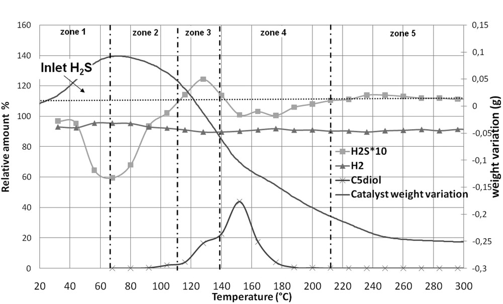
Thermogravimetric analysis of CoMo1C5diol under H2/H2S (89/11): evolution of the catalyst weight and of the relative amounts of H2 and H2S at the outlet of the reactor. The relative evolution of the intensity of a peak detected by GC and corresponding to C5diol elimination is also represented.
Quantitative analysis of Fig. 8. *The theoretical weight variation is calculated taking into account the evolution of outcoming H2S and considering that consumed H2S is only adsorbed on the solid. **Quantification on H2S evolution is performed by integrating the outcoming H2S curve and considering that the total gas flow is the same at the inlet and at the outlet of the reactor (100 mL min−1).
| Zone | Temperature range (°C) | Exp weight variation | Theo* weight variation | Quantification on H2S evolution** | Other comments |
| Zone 1 | 20–70 | +0.092 g | +0.09 g | Incoming H2S: 0.012 mol Outcoming H2S: 9.2.10−3 mol Consumed H2S: 2.8.10−3 mol | |
| Zone 2 | 70–110 | −0.057 g | +0.07 g | Incoming H2S: 9.8 10−3 mol Outcoming H2S: 7.6 10−3 mol Consumed H2S: 2.2.10−3 mol | H2O loss εC5diol loss |
| Zone 3 | 110–140 | −0.099 g | −0.016 g | Incoming H2S: 7.4.10−3 mol Outcoming H2S: 7.9.10−3 mol Released H2S: 5.10−4 mol | C5diol loss H2O loss |
| Zone 4 | 140–210 | −0.14 g | +0.016 g or +0.032 g | Incoming H2S: 1.7.10−2 mol Outcoming H2S: 1.6.10−2 mol Consumed H2S: 10−3 mol | C5diol loss H2O loss |
| Zone 5 | 210–300 | −0.048 | Incoming H2S = Outcoming H2S | H2O loss |
This thermogravimetric study of the gas phase sulfidation of CoMoRef and CoMo1C5diol shows that the organic agent modifies the sulfidation of the catalyst. Firstly, at low temperatures it inhibits the amount of adsorbed H2S molecules and the sulfidation of the active metals. Secondly, at higher temperatures, the loss of C5diol induces a new H2S uptake that is not observed on the CoMoRef.
3.3.2 XPS and EPR study of the sulfidation
All the aforementioned results suggest that the C5diol modifies the H2S consumption during activation. Thus it is very interesting to know how the sulfidation of both molybdenum and cobalt is affected.
- - Characterization of the sulfide catalysts
For both solids, after sulfidation at 350 °C, the spectra of Mo3d core level (see Fig. 7A,C) exhibit a Mo3d5/2 photopeak at about 228.8 eV characteristic of MoS2, the shoulder at BE = 225.8 eV being due to the S2s photopeak while the Co2p spectra (see Fig. 7B,D) exhibit a main peak at about 778.8 eV characteristic of Co in sulfur environment [54]. Table 5 summarizes the results of the decomposition of the XPS spectra of the CoMoRef and CoMo1C5diol catalysts sulfided at 350 °C for 3 h. This quantitative analysis has been performed in order to determine the Mo sulfidation degree and the proportion of Co involved in the CoMoS phase. It appears that modification of CoMoRef with C5diol induces a higher Mo sulfidation degree. Similarly, the total amount of Co atoms in the sulfided state is higher for the modified solid. This results in a higher fraction of the CoMoS phase. It is interesting to note that when the Co sulfidation degree increases upon modification from 40 to 50%, the CoMoS percentage increases from 30 to 40% while the fraction of Co9S8 does not change. For each CoMoRef catalyst and CoMo1C5diol catalyst, the number of promoted active sites for 100 g of catalyst (corrected by the loss of ignition) was calculated according the following formula:
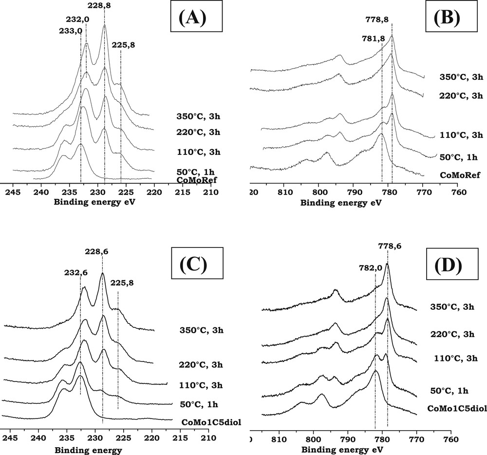
Mo3d and Co2p XPS spectra of CoMoRef and CoMo1C5diol after sulfidation (H2/H2S, 90/10) at various temperatures. (A): Mo spectra of CoMoRef; (B): Co spectra of CoMoRef; (C): Mo spectra of CoMo1C5diol; and (D): Co spectra of CoMo1C5diol.
XPS data of the CoMoRef and CoMo1C5diol catalysts sulfided at 350 °C.
| Catalysts | CoMoRef | CoMo1C5diol |
| Mo sulfidation degree (%) | 60 | 70 |
| Relative amount of the CoMoS phase (%) | 30 | 40 |
| Relative amount of Co9S8 (%) | 10 | 10 |
| Relative amount of Co oxide (%) | 60 | 50 |
NCoMoS is the number of promoted active sites for 100 g of catalyst,
%CoCoMoS is the relative % of Co implied in the CoMoS phase,
nCo is the number of Co atoms for 100 g of catalyst.
Table 6 presents the obtained numbers of CoMoS sites for the two solids versus the thiophene HDS rates. The ratios NCoMoS-CoMo1C5diol/NCoMoS-CoMoRef and HDS rate CoMo1C5diol/HDS rate CoMoRef are the same, which means that the improvement of the thiophene HDS rate is directly correlated to the increase in the number of CoMoS sites. To understand the origin of this higher amount of active sites, the sulfidation of the two solids was followed by XPS and EPR.
- - Characterization of the genesis of the active phase
Comparison between the number of active sites (for 100 g of catalysts) and the catalytic performances in thiophene HDS of the studied solids.
| Catalysts | Number of active sites for 100 g of catalyst | Thiophene HDS rate (mol s−1 g−1) |
| CoMoRef | 8.42.1021 | 4.0.10−8 |
| CoMo1C5diol | 1.13.1022 | 5.6.10−8 |
| Ratios CoMo1C5diol/CoMoRef | 1.35 | 1.40 |
Fig. 7A,B present the evolution of the Mo3d and Co2p XPS spectra of the CoMoRef catalyst at different steps of activation. After activation at 50 °C for 1 h, the features of sulfidic Mo and sulfidic Co species are observed, which means that the sulfidation of both metals starts at room temperature in agreement with the thermogravimetric study, which shows an important H2S consumption at low temperatures. Upon increasing the sulfidation temperature from room temperature up to 350 °C the Mo XPS features of the oxide components (peaks at 233 and 236.1 eV) gradually disappear while those of the sulfide ones appear (peaks at 228.8 and 232 eV). Thus, molybdenum sulfidation starts at room temperature and finishes at 350 °C. Evolution of Co is different. Indeed during the activation the intensity of the oxidic state Co contribution (BE = 781.8 eV) decreases while the sulfidic state Co one increases from low temperatures to 220 °C. Then the XPS spectra obtained at 220 °C and 350 °C are similar. So cobalt sulfidation starts at ambient temperature and seems complete after 3 h at 220 °C.
Regarding the CoMo1C5diol, XPS characterizations have been performed at the same sulfidation steps as for the above CoMoRef study (Fig. 7C,D). The relative evolution of Mo and Co XPS features is different compared to that of CoMoRef. Indeed after sulfidation at 50 °C the Mo3d and Co2p XPS spectra exhibit the features characteristic of the starting oxide species with those of the sulfide ones but the relative intensities of the latter ones are largely lower than in the case of CoMoRef. This suggests that the presence of the organic agent inhibits the sulfidation of both metals at low temperature. Moreover the relative intensity of the S2s component at 225.8 eV is very low thus confirming the thermogravimetric study, which shows that C5diol inhibits the adsorption of H2S and the sulfidation at low temperatures. This inhibiting effect of the organic agent on the sulfidation is also evidenced by the in situ EPR study of the sulfidation of these two catalysts. Indeed the comparison of the evolutions of the EPR spectra of CoMoRef and CoMo1C5diol obtained during their gas phase sulfidation indicates that the formation of MoV species is slackened when the oxidic precursor was previously modified with the C5diol (see Fig. 8A,B). Indeed the intensity of the EPR spectra (obtained at g = 1.93 for both solids and thus characteristic of the MoV oxo or oxysulfide species [55,56]) increases more slowly at low temperatures in the case of CoMo1C5diol solid. The Mo and Co XPS spectra obtained after sulfidation at 110 °C for 3 h show that sulfidation of the metal has progressed, which is not surprising since the thermogravimetric study (see Fig. 6) shows that C5diol is eliminated from 110 °C to about 200 °C, inducing a second H2S consumption in this temperature range. Then from 110 to 350 °C the intensities of the peaks characteristic of MoS2 and sulfided Co increase continuously while those of oxidic components decrease. This evidences the sulfidation of molybdenum and cobalt atoms upon increasing the temperature up to 350 °C.
- - Characterization of the carbon content during sulfidation
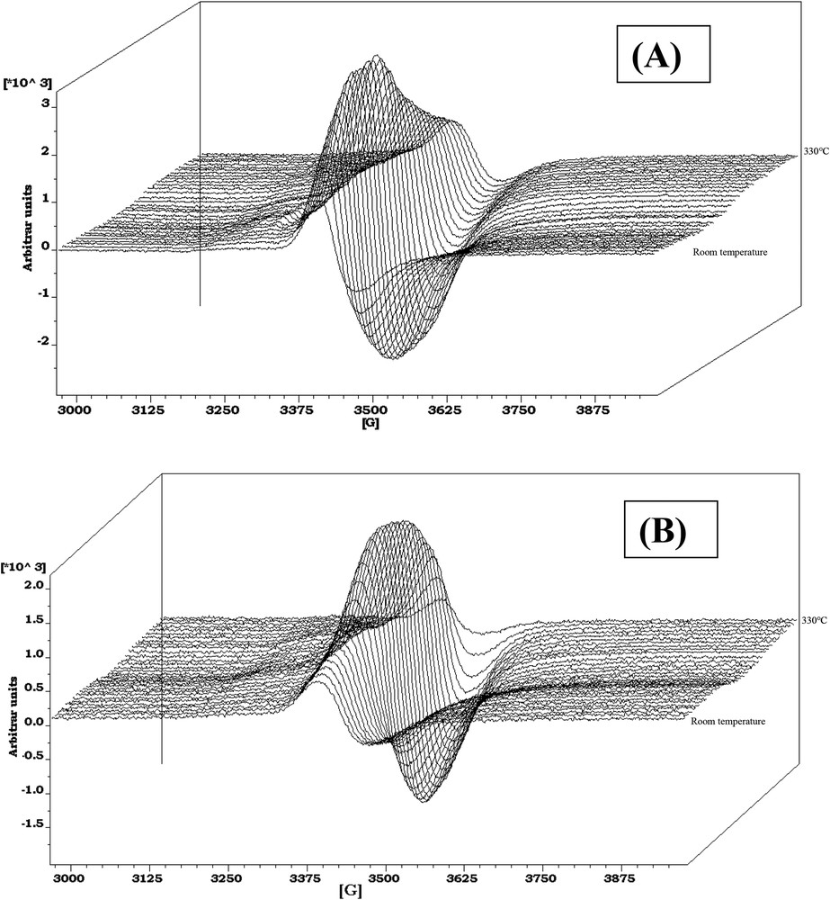
In-situ EPR spectra obtained during sulfidation (H2/H2S, 90/10) from room temperature to 330 °C. The first spectrum corresponds to the oxidic precursor and the following spectra are taken every 10 °C: (A) CoMoRef; (B) CoMo1C5diol.
In order to see if the organic additive turns into coke species during activation, the carbon content was also determined during sulfidation. Table 7 presents the IC1s/IAl2p XPS ratios for the two catalysts at each step of activation. For CoMo1C5diol this ratio drastically decreases between 110 and 220 °C; this temperature range corresponds to that of decomposition of pentanediol, in agreement with TGA data. This indicates that carbon issued from the decomposition of pentanediol does not lead to coke formation that would remain on the catalyst surface. The value at the end of sulfidation is 0.32 which can be compared to that of CoMoRef, 0.25. The remaining part of carbon may then be attributed to carbon contamination during XPS analysis.
IC1s/IAl2p XPS ratio for the CoMoRef and CoMo1C5diol solids at different steps of the activation.
| Samples | CoMoRef | CoMo1C5diol |
| Before activation | 0.20 | 1.00 |
| 110 °C – 3 h | 0.25 | 0.95 |
| 220 °C – 3 h | 0.25 | 0.37 |
| 350 °C – 3 h | 0.25 | 0.32 |
This study shows that the sulfidation of Co is achieved before that of Mo in CoMoRef as already observed by several authors [27–29,34,35] while in the case of CoMo1C5diol the sulfidation of both Mo and Co species is partly inhibited at low temperatures and occurs simultaneously up to 350 °C. Moreover, the results indicate that the organic agent favours a higher amount of CoMoS sites formed during sulfidation.
3.3.3 Electron microscopy
The sulfided catalysts were analyzed using TEM to determine the effect of the addition of C5diol on the MoS2 morphology. Typical TEM images are given in Fig. 9 whereas the distribution of the length and stacking degree of MoS2 slabs are reported in Figs. 10 and 11. These figures show that the use of C5diol induces a decrease in the length of the MoS2 slabs while stacking is not really affected. The average size of the MoS2 slabs is 33 Å for CoMoRef and 27 Å for CoMo1C5diol. Taking into account the geometrical Kasztelan's model [57], it is suggested that more edge and corner sites are available for Co promotion after sulfidation of the modified oxidic precursor.
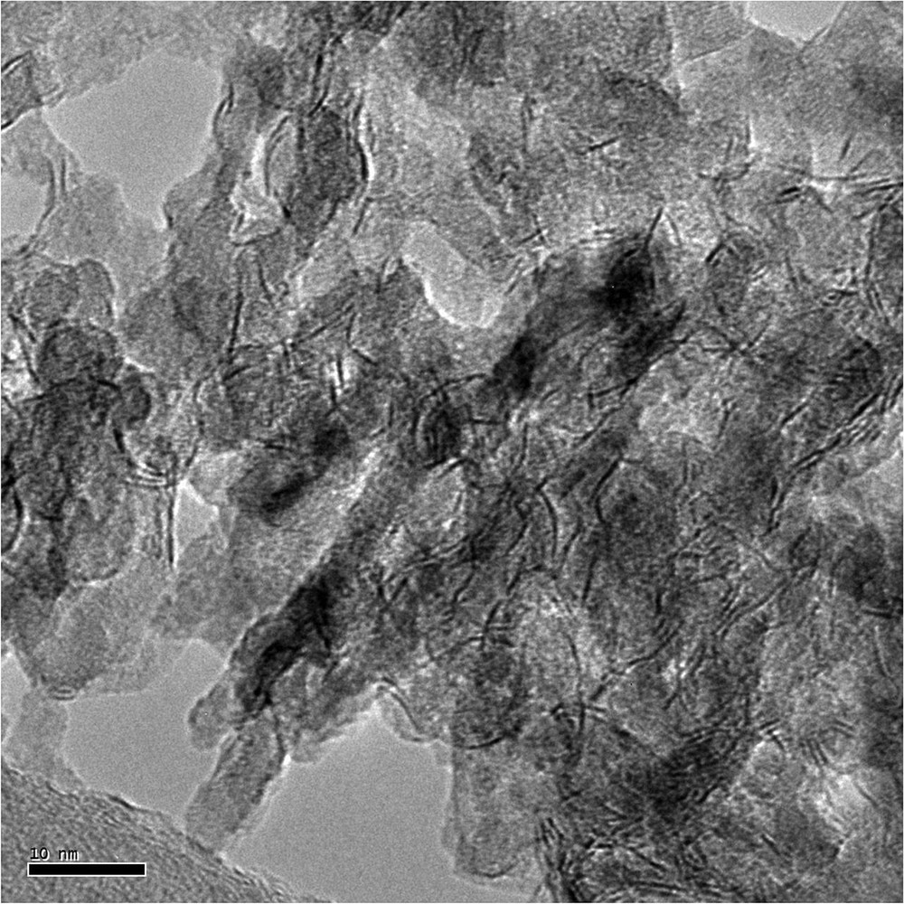
Example of the HREM micrograph of sulfided CoMo1C5diol.
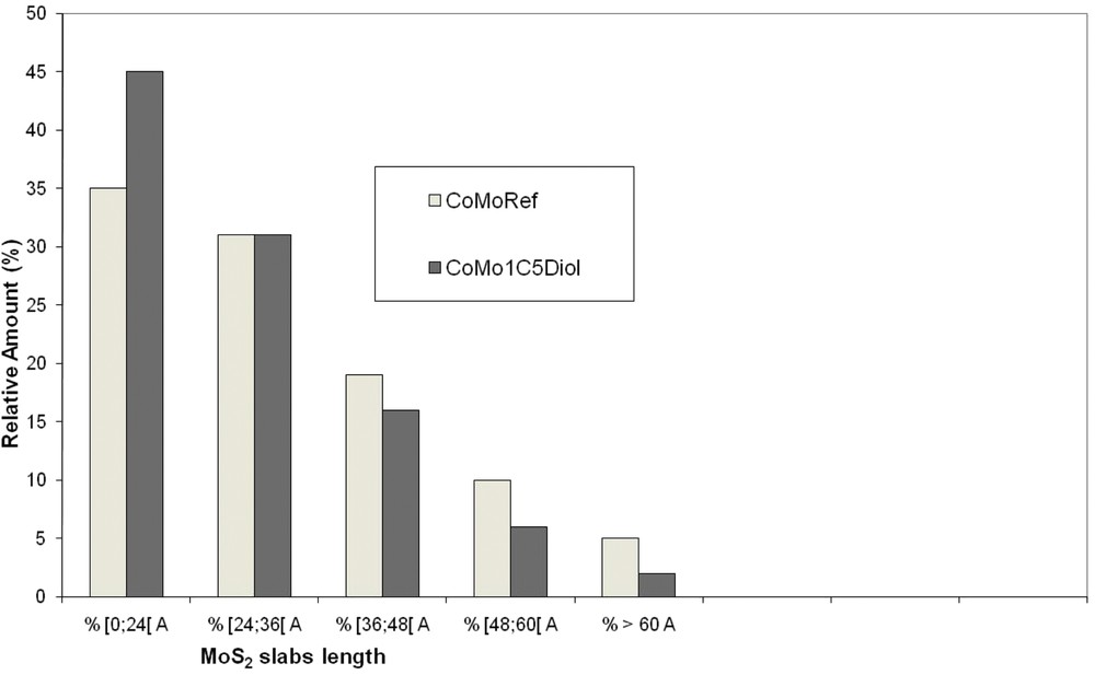
Distribution of the MoS2 slab length for CoMoRef and CoMo1C5diol catalysts after sulfidation under the gas phase at 350 °C for 3 h.
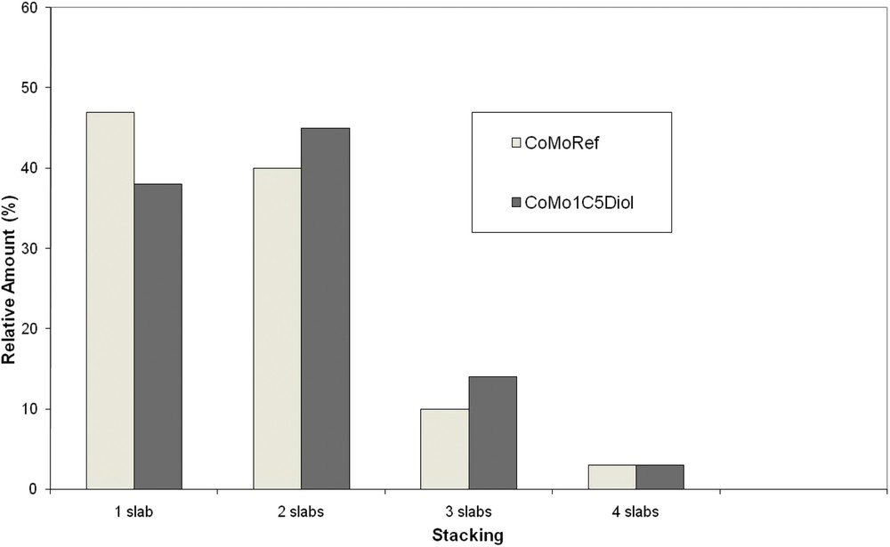
Distribution of the MoS2 slab stacking for CoMoRef and CoMo1C5diol catalysts after sulfidation under the gas phase at 350 °C for 3 h. Slabs with more than four layers are not represented due to their very low amount.
4 Discussion
In a previous work we showed that the catalytic performances of such a conventional oxidic precursor can be improved through its modification by impregnation of a chelating agent such as thioglycolic acid (TGA). The improvement of the performances was assigned to the complexation of Mo and Co atoms with TGA, which induces modifications of the amount and morphology of the active phase [7,8]. In the present work we show that the impregnation of a classical CoMo based oxidic precursor with a weak chelating agent such as 1,5-pentanediol in aqueous solution also induces a large improvement in the thiophene HDS conversion. After characterization of the active catalysts (in their sulfided form) this improvement is clearly explained by an increase in the number of CoMoS sites, which is linearly correlated to the increase in the HDS rate obtained thanks to the use of this organic agent. It is thus evidenced that this improvement in catalytic performance is only due to the increase in the number of CoMoS sites. This is in accordance with previous studies, which have shown that such a type of additive also allows for improving the catalytic performances in HDS of straight-run gasoline. The authors of this work have shown that the HDS performance is correlated to the number of CoMoS sites [10]. More recently a combined theoretical and experimental study of the role of glycol type additives showed that the catalytic performance in toluene hydrogenation was not only dependent on the amount of the CoMoS phase but was more probably driven by the number of mixed Co-Mo sites present at the MoS2 edges [58]. However their best catalysts are most often those which present the highest global amounts of CoMoS sites.
To understand how it is possible to increase the number of CoMoS sites in sulfided catalysts, it is necessary to consider the morphology of the active phase. Indeed when comparing the slabs of the two catalysts it is seen that the use of C5diol induces mainly a decrease in the slab length, which means that more edge and corner sites are available for Co localisation. Moreover XPS analysis showed that the Mo sulfidation level is increased upon modification, which means that a higher amount of Mo atoms is in the form of MoS2 slabs. Considering all these data (CoMoS%, MoS2%, MoS2 average length) we have calculated the number of Co atoms per slab. Table 8 presents the calculations and the results obtained for the two catalysts. Firstly it appears that all the additional Co atoms that are involved in the CoMoS phase (upon modification of CoMoRef with C5diol) can be incorporated into the active phase since the increase in NCoMoS is accompanied by an increase in NMoS2 and a decrease in the slab length, which induces an increase in the number of edges that are available for Co occupation. So TEM and XPS results are consistent. Secondly it is observed that whatever the catalyst, the substitution rate of Mo by Co atoms on the edge and corner sites (TCo-E+C) is the same and corresponds to a Mo substitution equal to 50%, in agreement with theoretical studies that have proposed that Co atoms only occupy the S-edges of the MoS2 slabs [59,60]. These results show that the increase in the number of CoMoS sites is obtained through an increase in the global number of “half promoted” MoS2 slabs with a lower size and not by increasing the promotion rate of the MoS2 slabs.
Comparison between the number of active sites (for 100 g of catalysts) and the catalytic performances in thiophene HDS for the studied solids.
| /100 g catalyst | CoMoRef | CoMo1C5diol |
| Number of Mo atoms (nMo) | 7.25.1022 | 7.25.1022 |
| Number of Co atoms (nCo) | 2.81.1022 | 2.81.1022 |
| Number of Mo in the MoS2 phase | 4.35.1022 | 5.08.1022 |
| Number of Co in the CoMoS phase | 8.43.1021 | 1.13.1022 |
| MoS2 slab average size (Å) | 33 | 27 |
| Number of (Co + Mo) per slaba (nCo+Mo)sl | 108 | 75 |
| Number of edges and corners per slaba (nE+C)sl | 33 | 27 |
| Number of slabs | 4.8.1020 | 8.3.1020 |
| Number of Co at per slab (nCo)sl = NCoMoS/Nsl | 17 | 14 |
| Substitution rate of MoE+C by Co TCo-E+C = (nCo)sl/(nE+C)sl | 0.52 | 0.52 |
a Number of (Co+Mo) per slab ((nCo+Mo)sl) and number of edges and corners per slab ((nE+C)sl) are estimated from the geometrical Kasztelan's model [57] taking into account the slab length as determined by statistical analysis of TEM images. As it is admitted that Co in the CoMoS phase is in substitution of Mo atoms at the edges of the MoS2 slabs, the total number of atoms in a slab, that is the (nCo+Mo)sl number, corresponds to Mo atoms in the MoS2 phase and Co atoms in substitution on the edge (CoMoS).
We will see now how the observed modifications of the CoMoS phase can be induced by the use of this organic agent. Raman and XPS characterizations of the oxidic precursor show that this organic additive does not modify the nature and the dispersion of the supported oxomolybdate phase. Several studies have reported the use of chelating agents such as citric acid or ethylenediamine with the objective of improving the dispersion of Mo and Co when preparing oxidic precursors. But the chelating agents were introduced into the impregnating solution with the metal salts [2,12,13,22–24,61]. In those studies the main role of the additives was to stabilize the impregnating solution and consequently to inhibit the formation of any bulk oxides such as MoO3 or CoMoO4 upon calcination. Moreover whatever the complexing agent used in those studies, a calcination step was performed before sulfidation. Consequently the same type of oxomolybdate species was sulfided, calcination being a levelling step for these modifications [2]. Other authors observed that addition of polyethylene glycol with molecular weight 400 (PEG) to the impregnating solution was maintaining a high dispersion of molybdenum and cobalt and was suppressing their aggregation during the oxidic precursor preparation [25,26]. But in their studies these authors have calcined their catalysts after the impregnation. Therefore, the role of PEG as suggested by these authors resembles that of the aforementioned ethylenediamine or citric acid. Recently Costa et al. showed, mainly by Raman spectroscopy, that addition of triethyleneglycol (TEG) on dried CoMo and CoMoP catalysts leads to a change in the dispersion of the supported entities even if no bulk oxide (MoO3, CoMoO4, Co3O4) was evidenced on the starting oxidic precursor [9]. They proposed that the TEG-based aqueous solution acts as a solvent via a redissolution/redispersion phenomenon inducing, for CoMo oxidic precursors, the transformation of non-well-defined oxomolybdate species into AlMo6O24H63− Anderson entities. In the case of CoMoP solids, this redissolution leads to the formation of PCoMo11O407− type species. This phenomenon is less important for the calcined oxidic precursor because of stronger molybdate-support interactions. Such a redissolution effect could also be considered for 1,5-pentanediol aqueous solution. However, in our case the XPS and Raman characterizations of CoMoRef and CoMo1C5diol do not permit to evidence any clear modification of the oxomolybdate phase after impregnation of this organic agent. Regarding cobalt, we just observe an increase in the ICo2p/IAl2p ratio, which can be interpreted according to the UV spectra as a little decrease in the relative amount of Co atoms in tetrahedral sites of the alumina lattice to the benefit of the octahedral ones.
After sulfidation, we can see that the modification of CoMoRef by C5diol provokes an enhancement of the molybdenum and cobalt sulfidation degree. For Mo, while we cannot detect any modification of the nature of the supported species we can imagine that this higher sulfidation degree could be due to a decrease in the Mo–alumina interaction induced by the impregnation of the C5diol solution. For Co, the higher sulfidation level may originate from the extraction of some Co atoms in tetrahedral sites since it is known that these species are less sulfidable than the octahedral ones.
The major effects of additive impregnation were observed during sulfidation. Indeed the thermogravimetric study of the gas phase sulfidation of CoMoRef and CoMo1C5diol shows that the organic agent modifies the adsorption of H2S on the catalyst during sulfidation. At low temperatures, while H2S is adsorbed in a large amount on CoMoRef, the presence of C5diol after modification inhibits the amount of adsorbed H2S molecules and thus the sulfidation of the active metals. This decrease in H2S adsorption on the modified solid can proceed via adsorption of C5diol on the surface or pore blocking. The initial catalyst presents a surface area of 260 m2/g and a water pore volume of 0.9 cm3/g. After impregnation of 1 g of catalyst by pentanediol and drying for water elimination, the remaining content of diol is 0.125 g (which fits the Mo/diol ratio of 1). This corresponds to 2.7 molecules of diol per nm2. Moreover the volume occupied by the 0.125 g of diol represents about only 10% of the catalyst pore volume. Considering that 3 times less H2S is adsorbed at low temperature after modification, we can propose that pentanediol may block some pores but is mainly dispersed on the surface, in order to achieve such an effect. On the contrary at higher temperatures, the loss of C5diol induces a new H2S consumption, which is not observed on CoMoRef. The XPS study of the gas phase activation of the two solids shows that these phenomena influence the relative rate of sulfidation of Mo and Co atoms. Indeed, in CoMoRef, sulfidation of both metals starts at room temperature and sulfidation of Co is achieved before that of Mo. In the case of the CoMo1C5diol, the sulfidation of both Mo and Co species is inhibited at low temperatures but both metals are sulfided simultaneously up to 350 °C. This simultaneous sulfidation originates from the delay of the metals sulfidation at low temperature. The second uptake of H2S, which is observed during the loss of C5diol, could also be at the origin of this simultaneous sulfidation. It presents two main advantages leading to the best catalytic performances as we discussed in previous papers [7,8]. Firstly, it permits to delay the sulfidation of cobalt and thus to inhibit the formation of Co9S8 allowing to have more Co atoms in the decoration position. This is in agreement with our XPS results, which show for the CoMo1C5diol catalyst that the higher amount of sulfided Co is incorporated preferentially into the CoMoS phase than in the bulk Co sulfide. As discussed in many studies [27–35], the complete sulfidation of Co before the formation of MoS2 slabs yields bulk Co9S8, whose atoms are not able to promote the MoS2 slabs at higher temperatures. The use of well chosen chelating agents enables to overcome this problem by retarding the sulfidation of Co after the formation of the MoS2 slabs. In this work we show that Mo and Co sulfidation occurs simultaneously thanks to the use of a non-chelating agent, which is a way to delay sufficiently the Co sulfidation and consequently to optimize the formation of the CoMoS phase. Secondly, the simultaneity of the sulfidation of both Co and Mo atoms can be related to the decrease of the MoS2 slab size evidenced for CoMo1C5diol as the migration of the Co atoms on the MoS2 edges during the formation of the disulfide slabs blocks their growth.
5 Conclusion
The performance of a CoMoP/Al2O3 catalyst in HDS of thiophene can be successfully improved through the modification of the oxidic precursor by impregnation with 1,5-pentanediol aqueous solution. It is shown that the better HDS performance of the modified solid in the HDS of thiophene is linearly correlated to the increase in the number of CoMoS active sites. This higher number of CoMoS sites is due to the increase in the Mo sulfidation degree, the relative CoMoS % and the smaller size of the MoS2 slabs.
A detailed characterization of the genesis of the active phase allowed us to describe the exact role of the pentanediol modifying molecule.
- - No Mo or Co complexes are observed on the oxidic precursor after its impregnation, which is in accordance with the weak chelating properties of this organic compound.
- - Concerning Mo, no redissolution/redispersion effect of this organic compound as observed for glycol type compounds can be characterized. However as, after sulfidation, an enhancement of the molybdenum sulfidation degree is observed, a decrease in the Mo--alumina interaction induced by the impregnation of the C5diol solution could be possible.
- - Regarding Co, the impregnation of pentanediol induces a little decrease in the relative amount of Co tetrahedral species that are known to be beneficial to the promotion of the MoS2 slabs after sulfidation. Indeed the Co sulfidation degree is also improved upon modification.
- - The main effect of the organic molecule is to delay the sulfidation of the supported metals, leading to a simultaneous sulfidation of both Co and Mo atoms, which induces lower MoS2 slab size and higher CoMoS%. The modification of the sulfidation is due to the interaction between 1,5-pentanediol and the solid that inhibits the adsorption of H2S on the solid at low temperatures and thus retards the sulfidation of the metals.
Acknowledgements
The authors want to thank Total Research and Technology Feluy, Zone industrielle CB-7181, Feluy, Belgium, for financial support.
The Chevreul Institute (FR 2638), the “Ministère de l’Enseignement supérieur et de la Recherche”, the “Région Nord-Pas-de-Calais and FEDER are acknowledged for supporting and funding this work (TEM and XPS facilities).