

1 Introduction
The methanol-to-propylene (MTP) process was designed as a prospective method for production of light olefins, especially propylene from relatively low-priced methanol [1,2]. The commercialized MTP process is the Lurgi technology, which has a large amount of methanol conversion [3]. In the Lurgi technology, MTP process takes place in a fixed-bed reactor over the MFI-type zeolite catalyst, which is called H-ZSM-5 [4]. Primarily, methanol is dehydrated into the equilibrium mixture of methanol, dimethyl ether (DME), and water according to the following reactions [5,6]:
| (1) |
| (2) |
| (3) |
| (4) |
| (5) |
| (6) |
| (7) |
| (8) |
| (9) |
Consecutively, higher olefins, alkanes, cycloalkanes, and aromatics are generated via methylation, hydrogen transfer, oligomerization, and cyclization (aromatization) reactions. The reaction scheme in Fig. 1, which was suggested by Bjørgen et al. [10], demonstrates the MTP reaction.
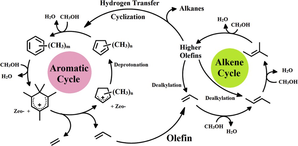
Dual-cycle mechanism of the MTP reaction proposed by Bjørgen et al. [10].
In the current investigation, to carry out the MTP reaction, the high-silica conventional H-ZSM-5 catalyst with a Si/Al ratio of 220 was synthesized by the hydrothermal method. To improve the catalytic activity of the conventional H-ZSM-5 catalyst in the MTP process, many investigations were conducted [11–14], particularly by adding different promoters via the impregnation method. For example, Losch et al. [15] synthesized ZSM-5 zeolites and modified them with hydrofluoric, hydrochloric, and phosphoric acids. The modified catalysts resulted in the same ZSM-5 crystal morphology and similar catalytic performance. Missengue et al. [16] presented a method for applying South African coal fly ash by extracting metals such as Al and Fe with concentrated sulfuric acid and by using solid residue as a precursor for the synthesis of ZSM-5 zeolite. The prepared catalyst presented full methanol conversion during 15 h on stream in the methanol to olefins reaction. Ahmadpour and Taghizadeh [17] investigated the MTP reaction over high-silica mesoporous ZSM-5 zeolites. The best propylene selectivity and catalytic lifetime were 47.2% and 80 h, respectively. Behbahani and Mehr [18] reported that Strontium (Sr) promoted the ZSM-5 catalyst with a low Si/Al ratio of 31.5, using the wet impregnation method. It was shown that the Sr promoter reduced gas and increased liquid products. Therefore, Sr-promoted ZSM-5 catalyst was more suitable for methanol to aromatics or methanol to hydrocarbons reaction. It was concluded by Liu et al. [19] that propylene selectivity was modified over the H-ZSM-5 catalysts, which were impregnated by the promoters W, Ce, Mn, Fe, and Cr. The W-impregnated H-ZSM-5 catalyst had the best performance in propylene selectivity. In comparison with the common impregnation method, the framework substitution by transition metals improved the strength of acidic sites more effectively. This has been proven by temperature-programmed desorption of ammonia (NH3-TPD) profiles [20,21]. The modified acidic sites reduce the rate of side reactions such as hydrogen transfer reactions including hydrogenation/dehydrogenation of certain hydrocarbons, oligomerization, and cyclization reactions. Few studies have shown that framework substitution by transition metals was used for catalysts of the MTP reaction. The M-substituted (M: Al, Fe, and Ga) MFI metallosilicates were synthesized by Jin et al. [20] using the hydrothermal method. Among the prepared metallosilicate catalysts, Fe-substituted MFI metallosilicate (H-FeAlMFI) demonstrated the best activity in the MTP reaction. Recently, Hadi et al. [21] synthesized the nanosheets of M-substituted (M: Mn, Ce, and W) MFI-type zeolites. The W-substituted MFI zeolite nanosheets had the best performance in the MTP reaction. Nevertheless, with respect to the literature survey, the W-substituted MFI metallosilicate (H-WAlMFI) was not presented as the potential catalyst for the MTP reaction in the literature. Therefore, in the present work, high-silica W-substituted MFI metallosilicate catalysts with gel Si/Al ratio of 220 and Si/W ratios of 50, 100, and 250 were synthesized using a hydrothermal technique.
The feedstock of the MTP process was composed of the specified mixture of methanol and water [22]. Methanol is one of the most promising derivatives from natural gas [23,24]. Huge quantities of methanol are produced by syngas, which is obtained via steam reforming of natural gas [25]. The liquid mixture of methanol and water should be vaporized before introducing to the reactor. Generally, in the laboratory scale of the MTP process, a syringe pump or micropump was used for pumping of the liquid feed into the preheater for vaporization [26]. Then, in the mixing chamber, the vaporized feed and the carrier gas of the process (an inert gas, e.g., N2) were mixed and finally entered into the catalytic bed [20,27]. In the current investigation, the catalyst evaluation examinations were implemented for all the prepared catalysts using the aforementioned conventional feed-supply system.
To elucidate the suitability of the conventional feed-supply system on important parameters of the MTP process, for example, methanol conversion, propylene yield, and catalytic lifetime, time on stream (TOS) examinations were performed for the best catalyst using both the conventional and novel feed-supply methods. The novel technique used the piezoelectric ultrasonic effect for provision of MTP feed. The piezoelectric ultrasonic effect evaporates the liquid feed at room temperature. In other words, the liquid feed is converted into the gas phase by using the piezoelectric ultrasonic effect without boiling. The liquid evaporation phenomenon at room temperature by means of the piezoelectric ultrasonic effect was previously reported by Phanphanit and Cooper [28] and Briceño-Gutierrez et al. [29].
Watson et al. [30] carried out a complete review on piezoelectric ultrasonic effect and its wide applications as actuator. The first developed piezoelectric ultrasonic actuator was successfully used in cameras [31]. In recent years, the demand for piezoelectric ultrasonic actuators has increased. For instance, its application in the microrobotics industry [32], field of microelectromechanical systems [33], and the medical profession, particularly for minimally invasive surgery [34,35], has been reported. Also, devices were designed using piezoelectric ultrasonic vibratory energy for evaporation of water, gasoline, or other liquid fuels used in humidifiers, carburetors, fuel injectors in vehicles, and so forth [36]. To the best of our knowledge, the use of piezoelectric ultrasonic effect for delivering the feed of the MTP process has not been reported before. The theoretical bases of the piezoelectric ultrasonic effect and the device itself are reviewed in the following section.
2 Piezoelectric ultrasonic effect
2.1 Theoretical bases
Piezoelectric effect is the capability of special crystals to produce electrical charges in response to mechanical stress. Certain ceramics are known as special piezoelectric crystals. Needless to say, the unique feature of the piezoelectric effect is that it is reversible. It means that the crystals that demonstrate the direct piezoelectric effect (the creation of an electrical field when mechanical stress is used) also show the production of mechanical stress when an electrical field is used. Whenever piezoelectric crystal is under mechanical stress, a shift in the positive and negative charge centers in the crystal occurs, which leads to an external electrical field around it. The external electrical field either stretches or compresses the piezoelectric material when reverse of the piezoelectric effect takes place. The displacement of the piezoelectric crystal depends on its polarization and the polarity of the electrical charges. The simplified mechanism of the piezoelectric effect is shown in Fig. 2a.
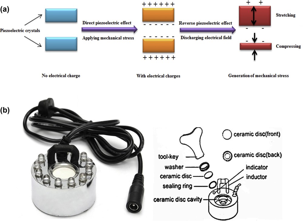
(a) Simplified mechanism of the piezoelectric effect; (b) piezoelectric ultrasonic device and its components.
2.2 Piezoelectric ultrasonic device
With continuous charging and discharging of electrical charges of the piezoelectric crystal or ceramic disc of the piezoelectric ultrasonic device, a stressed fluctuation is generated in that crystal. As a result of these stressed fluctuations, the piezoelectric crystal or ceramic disc starts to vibrate. The frequent vibrations of the piezoelectric crystal produce ultrasound waves in the surrounding area. The phenomenon of creation of ultrasonic waves by the piezoelectric effect is usually called the piezoelectric ultrasonic effect. To use the energy of the piezoelectric ultrasonic effect to evaporate a liquid like water, methanol, and so forth, the piezoelectric transformer, which is named transducer or ultrasonic generator, converts the electrical energy into the mechanical energy. Consecutively, a high frequency is released by the vibration sector, which contains the resonant circuit. In other words, the piezoelectric transformer or piezoelectric ultrasonic device converts the electrical frequencies into the proportional mechanical oscillations. The mechanical oscillations contain ultrasonic waves, which move ingredients in an environment like a liquid environment (e.g., methanol and water solution).
In the present study, the piezoelectric ultrasonic device, including piezoceramic transformer, was placed at the bottom of a feed vessel. The feed vessel consisted of a liquid solution of methanol and water with specific composition. The ultrasound vibrations were transported through the liquid to liquid–air boundary layer by exciting the piezoelectric transformer. The frequent compression/decompression of the liquid column, which is above the piezoelectric transformer or piezoelectric ultrasonic device, formed cavitation near the liquid surface. Afterward, the capillary waves were generated and aerosols of methanol and water were dispersed from these capillary waves. The aerosols of methanol and water were immediately coalesced with air [30,37–39]. The piezoelectric ultrasonic device and its other forming components are shown in Fig. 2b. As previously explained and shown in Fig. 2b, the ceramic disc is the major part of the piezoelectric ultrasonic device that forms vibratory energy for evaporation of methanol and water solution. Table 1 shows the main characteristics of the piezoelectric ultrasonic device.
Main characteristics of the piezoelectric ultrasonic device.
| Rating voltage (V/AC) | Rating current (A) | Ultrasound frequency (kHz) | Size of ceramic membrane (mm) | Limited temperature (°C) | Life of ceramic membrane (h) |
| 24 | 0.95–1.1 | 40 | 16 | 0–40 | >3000 |
Ten hours after the TOS examinations, the feed effluents of the conventional and novel feed-supply methods were condensed and their methanol compositions were analyzed. In comparison with the conventional feed-supply system, it was observed that the feed composition was totally constant by the novel feed-supply technique. This seems to be useful in the TOS examinations. The supplementary explanations on the advantages of stable feed composition, which was obtained by the novel feed-delivering technique, are presented in Section 5.3. Moreover, with use of the piezoelectric ultrasonic device, the conventional process equipment such as syringe pump, preheater, and mixing chamber would be eliminated; therefore, this novel technique is a neat exemplification of process miniaturization or process intensification.
3 Experimental section
3.1 Materials
The first materials used were tetraethyl orthosilicate (SiC8H20O4, 99 wt %), sodium hydroxide (NaOH, 98 wt %), aluminum sulfate (Al2(SO4)3·18H2O, 98 wt %), sodium tungstate (Na2WO4·2H2O, 98 wt %), ammonium chloride (NH4Cl, 98 wt %), ammonium fluoride (NH4F, 98 wt %), and tetrapropylammonium bromide (TPAB; C12H28BrN, 99 wt %). All the materials were extra pure, supplied by Merck and Aldrich companies, and used as received without any further treatment.
3.2 Catalyst synthesis
The W-substituted MFI metallosilicates were synthesized by the hydrothermal technique following the modified methods given in Refs. [20,40,41]. The synthetic gel was provided with the molar composition of 100SiO2:0.2273Al2O3:xWO3 (x = 0.4, 1, and 2):18.9Na2O:20.5NH4F:12.5TPAB:3200H2O. The gel composition was adjusted to obtain Na-WAlMFI with Si/Al ratio of 220 and Si/W ratios of 50, 100, and 250. The individual precursors were added to water in the following order: ammonium fluoride, aluminum sulfate (as a source of aluminum), sodium tungstate (as a source of tungsten), TPAB (as the template), tetraethyl orthosilicate (as a silicon source), and sodium hydroxide. The mixture was severely agitated for 2 h after inserting all the precursors. In the aging process, the resulting gel remained statically for 24 h at room temperature. Then, to carry out the hydrothermal synthesis, the gel was transferred to the Teflon-lined stainless-steel autoclave at 170 °C for 72 h.
After that, the product was washed with water by means of a Buchner funnel. The resulting paste was dried at 100 °C for 12 h and subsequently calcined at 550 °C for 4 h in air atmosphere. Eventually, the ion-exchange method was used to prepare H-WAlMFI through Na-WAlMFI with the following procedure: the sample in the NH4 form was produced by a 1 mol L−1 ammonium chloride solution at 50 °C for 48 h of agitation. The H-WAlMFI was obtained by drying and calcination of the NH4 form in atmospheric air at 100 °C for 12 h and 500 °C for 6 h, respectively. The conventional H-ZSM-5 was synthesized using the same method described for the synthesis of the H-WAlMFI zeolites, without adding sodium tungstate.
The H-WAlMFI zeolites with gel Si/W ratios of 50, 100, and 250 were H-W(50)AlMFI, H-W(100)AlMFI, and H-W(250)AlMFI, respectively.
3.3 Process setup for catalytic activity
The catalyst performance evaluations were conducted under atmospheric pressure in a vertical plug flow reactor. The reactor consisted of a pyrex tube, which was 900 mm in length and 9 mm (ID) in diameter. The catalyst powder (1 g) was dispersed over a plug of quartz wool and inserted into the reactor. The length of a catalytic bed was 100 mm. Moreover, the blank experiment was carried out using the sole plug of quartz wool and no methanol conversion to the products was observed. The reactor was placed in an electrical furnace controlled by a proportional-integral-derivative controller, to supply the heat to the MTP reaction. The feed consisted of 50 mol % binary solution of methanol and water. According to the current investigations and some other studies [2,11,17,21,27,42], the feed composition with 50 mol % of methanol and 50 mol % of water is the optimal feed composition for the MTP reaction to produce more propylene.
Water vapor is applied as a diluent material in the feedstock. Water is inserted in feedstock of the MTP because of reduction in the rate of unwanted reactions such as cyclization and hydrogen transfer [19,22]. These secondary reactions lead to the production of heavy hydrocarbons from the light olefins. In the MTP reactor, water vapor is adsorbed on the surface of the catalyst, which delays the generation of high carbon hydrocarbons. The heavy cyclic hydrocarbons are capable of deactivating the catalyst by producing coke depositions. When there is lack of feedstock water, the catalyst samples are poisoned by coke residues and also deactivated via sintering of the catalyst particles in a highly exothermic MTP reaction [27,43]. Therefore, because of the delay in the catalyst deactivation by coke depositions and prevention of sintering of the catalyst particles, and also to increase the selectivity to light olefins, especially propylene, the feed consisted of 50 mol % of water.
The process of feed preparation by the conventional feed-supply system is explained in Section 1. The procedure of feed preparation via the novel feed-supply method for TOS examinations is as follows: the feed stream was prepared by passing nitrogen (N2) as the carrier gas of the process through the feed vessel containing the piezoelectric ultrasonic device. The piezoelectric ultrasonic device evaporated the liquid feed and converted it into methanol and water aerosols. Consecutively, the carrier gas of the process transferred the methanol and water aerosols to the catalytic bed of the MTP reactor. The catalytic experiments were carried out under optimum operational conditions: reaction temperature of 500 °C, methanol weight hourly space velocity of 2.5 h−1, and a methanol molar ratio in feed of 50%. The product of the MTP reaction was analyzed using Shimadzu 2010 plus model gas chromatograph (GC). The GC analyzer was equipped with HP-PLOT Al2O3S, Agilent capillary column (length, 50 m and internal diameter 0.53 mm), and flame ionization detector. Helium was used as the carrier gas of the GC. The flow diagram of the experimental setup is shown in Fig. 3. The conventional feed-preparing system and the novel feed-supply technique are shown by the red and blue boxes, respectively.
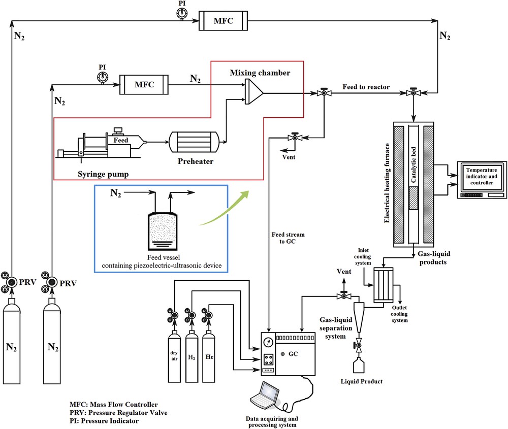
Schematic flow diagram of the experimental setup for activity examinations of catalysts in the MTP process, by comparing the conventional feed-supply system (the red box) and the novel feed-delivering technique (the blue box).
The methanol conversion, product selectivity, and product yield were calculated using Eqs. (10)–(12), respectively [2].
| (10) |
| (11) |
| (12) |
3.4 Techniques of catalyst characterization
The structure of conventional H-ZSM-5 and H-WAlMFI zeolites were determined via powder X-ray diffraction (XRD) using a Siemens D500 X-ray diffractometer. The prepared catalyst samples were analyzed at room temperature by XRD, using monochromatic Cu Kα radiation (wavelength λ = 0.154 nm at 2θ range from 4° to 70° with a scanning rate of 2°/min). Field emission scanning electron microscopy (FE-SEM) was used to specify the crystallite size and surface morphology of the catalysts. Likewise, the FE-SEM apparatus was equipped with an energy dispersive X-ray (EDX) analyzer. EDX is an extensively used analysis to determine the chemical species in a certain material using an FE-SEM technique. To conduct qualitative elemental analysis of the gold-coated catalyst samples, EDX technique was used. Both of the FE-SEM images and the EDX analyses were recorded by a MIRA3 TESCAN microscope. Transmission electron microscopy (TEM) images were recorded from the catalyst samples that were supported on a holey carbon-coated grid Cu mesh 300, using Zeiss EM10C equipment operated at 100 kV. The particle size distribution was analyzed using dynamic light scattering (DLS) technique recorded on a Microtrac (Nanotrac wave model) system. The textural properties of the conventional H-ZSM-5 and H-WAlMFI zeolites were revealed using the N2 adsorption/desorption analyses at 77.40 K by a NOVA 2000 Quanta Chrome USA device. Primarily, all the catalyst samples were evacuated at 300 °C under N2 flow for 3 h. The Brunauer–Emmet–Teller (BET) relation was used to determine the total specific surface area (Stotal) of the samples from the adsorption data, which were obtained from the linear part of the plot (in the relative pressure range of 0.05–0.25) with respect to IUPAC recommendations. The total pore volume (Vtotal) was calculated based on the N2 adsorbed volume at P/P0 = 0.99. The micropore area (Smicro) and micropore volume (Vmicro) were determined using the t-plot method in the P/P0 range of 0.1–0.4. Furthermore, the Barrett–Joyner–Halenda method was used to provide the mesopore size distribution from the adsorption isotherm. The mesopore volume (Vmeso) is the difference between the calculated total volume (Vtotal) and the micropore volume (Vmicro) [44]. To identify the surface acidity of the conventional H-ZSM-5 and H-WAlMFI zeolites with different Si/W ratios, the NH3-TPD was conducted using a BELCAT-A (BEL Japan, Inc.) apparatus. For this purpose, 35 mg of each catalyst sample was inserted into the U-tube chamber. The catalyst sample was primarily degassed under helium flow at 300 °C for 2 h at a heating rate of 10 °C/min. The catalyst sample was cooled to 60 °C and consecutively saturated by ammonia for 1 h. After saturation, the catalyst was purged with helium for 30 min due to removal of the physically adsorbed ammonia on the surface of the sample. The temperature of the catalyst was subsequently increased from 35 to 590 °C at a heating rate of 5 °C/min. The amounts of ammonia, which were desorbed from the catalyst, were measured by comparing the TPD areas with those of a standard sample, using a thermal conductivity detector [44]. The quantitative contents of Si, Al, and tungsten (W) were shown by inductively coupled plasma-atomic emission spectrometry (ICP-AES), which was conducted on an IRIS advantage ICAP full spectrum direct-reading emission spectrometer (TJA Solutions, USA) [45]. To carry out the ICP-AES analyses, the catalyst sample was precisely quantified and solved by a sufficient amount of hydrogen fluoride. Subsequently, to remove silicon fluoride, the solution was vaporized. Afterward, the residue was solved in 0.2 mol L−1 hydrogen chloride and the solution was adjusted to weak acidity with ammonia. Ultimately, the resulting solution was diluted and used for ICP-AES characterization [44–46].
For determination of the amounts of coke residues on the spent catalyst, thermogravimetric analysis (TGA) was used. The coke analyses were performed after TOS examinations. Temperature was increased to 800 °C at a constant rate of 10 °C/min under flowing dry air with a flow rate of 50 cm3 min−1 using a Perkin Elmer (RIS Diamond) thermal analysis instrument. The catalyst weight loss resulting from the reaction of deposited coke by oxygen was documented.
4 Results and discussion
4.1 Crystal structure and physicochemical properties of catalysts
Fig. 4 represents the XRD patterns of the catalyst samples. Distinct sharp diffraction peaks were observed in 2θ ranges of 8–15 and 20–30, and all of them corresponded to the typical pattern of the MFI zeolite crystal structure according to the Joint Committee on Powder Diffraction Standards data [47]. Some additional peaks can be observed on the XRD pattern of the tungsten-substituted MFI metallosilicate with a Si/W molar ratio of 50 (H-W(50)AlMFI) in comparison with XRD pattern of the conventional H-ZSM-5. According to the Joint Committee on Powder Diffraction Standards data and some other studies, such as those of Achary et al. [48], Xue et al. [49], and Haddouch et al. [50], these additional peaks belong to the AlWO4 structures (the higher the tungsten content of the catalyst sample, the stronger the peaks of AlWO4). Due to the low content of tungsten in the H-W(100)AlMFI and H-W(250)AlMFI zeolites, the peaks of AlWO4 structures cannot be determined accurately by their XRD patterns. With regards to the literature survey, the XRD pattern cannot support the details related to the low content of metal heteroatoms, which are substituted in the MFI zeolites [42,43]. With regards to the XRD patterns, the MFI-type crystal structure was indicated by circles, whereas the AlWO4 crystal structure was indicated by stars. Almost no other considerable change in phase and crystallinity was detected in W-substituted MFI metallosilicates. It is concluded that through the framework substitution by tungsten species and subsequent processes including ion-exchange and calcination treatments, the original structure of the MFI zeolite was not altered [51]. Uniform dispersion of the tungsten species throughout the MFI zeolite structure was demonstrated by lack of extra peaks in the XRD patterns [52–55]. The uniform dispersion of tungsten species was related to the low tungsten content and appropriate crystallization during the hydrothermal synthesis.
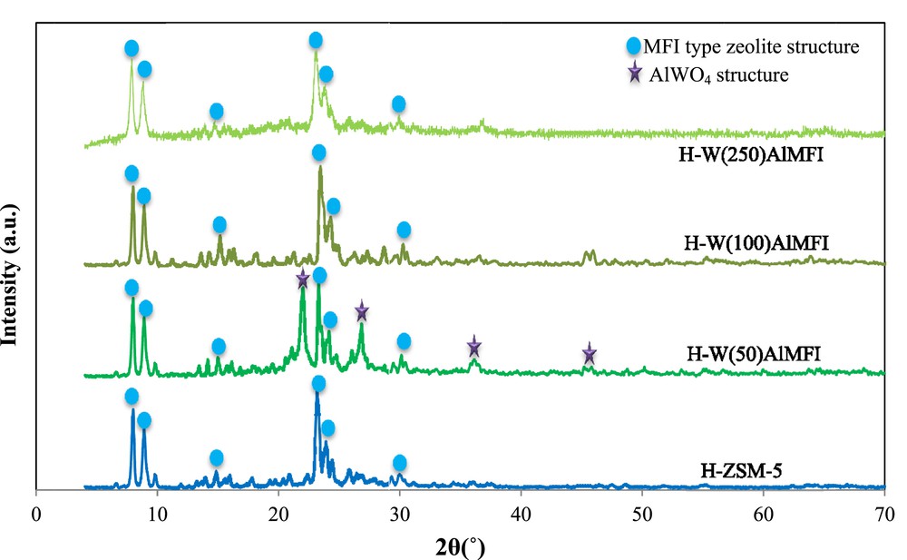
XRD patterns of the conventional H-ZSM-5 and W-substituted MFI metallosilicates (H-WAlMFI) with different ratios of Si/W.
The surface morphology of catalysts was identified by FE-SEM images (Fig. 5). Due to substitution of the tungsten species in the H-WAlMFI crystal structure, their external surface was not smooth. Particularly, the external surface of H-W(50)AlMFI zeolite was opaque as compared to the others, probably because there was more tungsten species in its framework, but the outer surface of the conventional H-ZSM-5 was smoother. The FE-SEM images of the H-WAlMFI catalysts showed the aggregation of W-substituted MFI zeolite crystals. Especially, the images of H-W(50)AlMFI zeolite illustrated a dense aggregation. The particle shapes of H-W(100)AlMFI and H-W(250)AlMFI were microspherical aggregates and their particle size distributions were considered to be comparatively uniform as compared to H-W(50)AlMFI zeolite. It shows that the tungsten species were well dispersed through the lattice of H-W(100)AlMFI and H-W(250)AlMFI zeolites. The high magnified FE-SEM images of the individual catalyst samples showed that the microspherical aggregates were formed from microsized crystals.
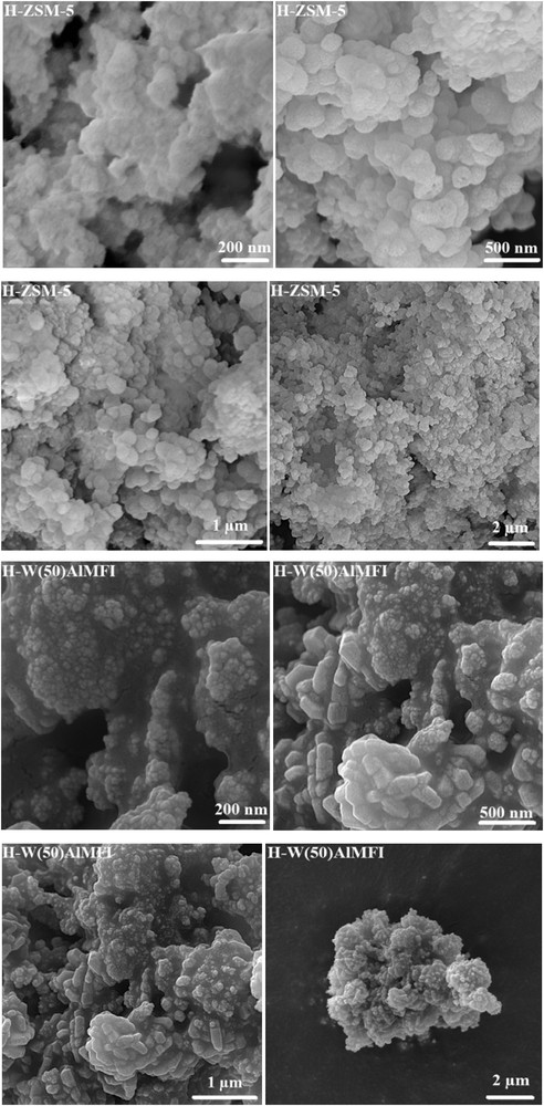
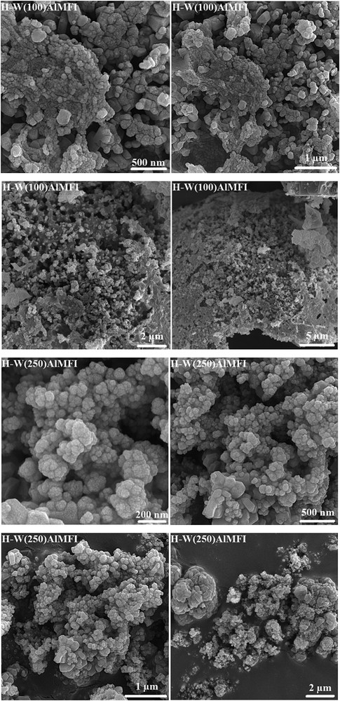
FE-SEM images of the conventional H-ZSM-5 and W-substituted MFI metallosilicates (H-WAlMFI) with different ratios of Si/W.
For investigation of the presence of considered elements in the structure of catalysts, qualitative elemental analysis was carried out by an EDX technique (Fig. 6). The results of elemental analyses demonstrated the presence of desired elements in the framework of all the samples. As expected, the peaks of a tungsten heteroatom were observed in EDX graphs of the H-WAlMFI zeolites (the higher the tungsten content of the zeolite framework, the stronger the EDX peaks of tungsten for that zeolite).
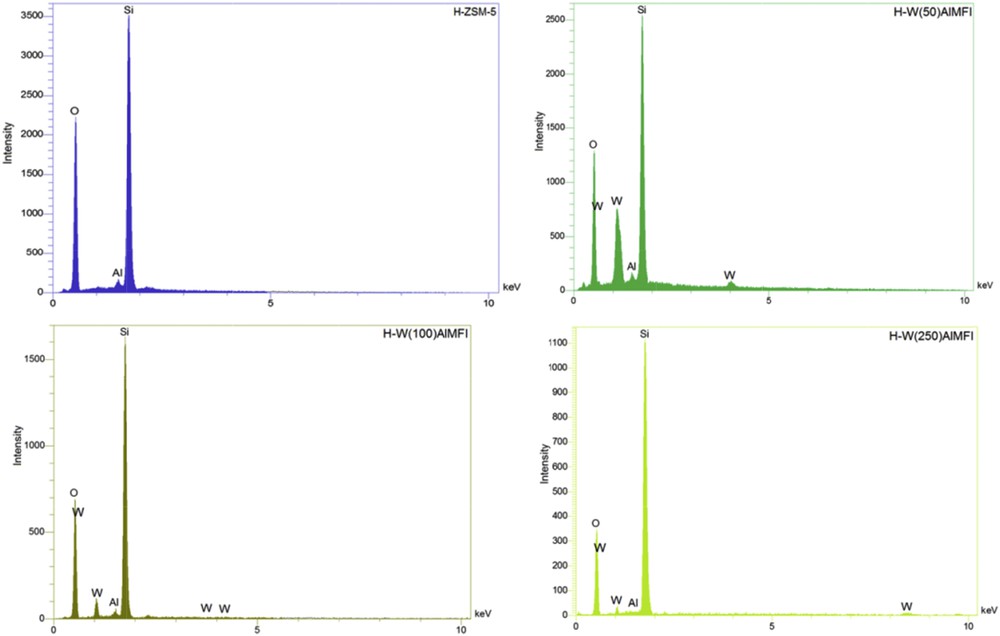
EDX graphs of the conventional H-ZSM-5 and W-substituted MFI metallosilicates (H-WAlMFI) with different ratios of Si/W.
Fig. 7 shows TEM images of the catalyst samples. Consistent with the high magnification FE-SEM images, the TEM images confirmed that the microspherical aggregates of the catalyst samples were made of microsized crystals.
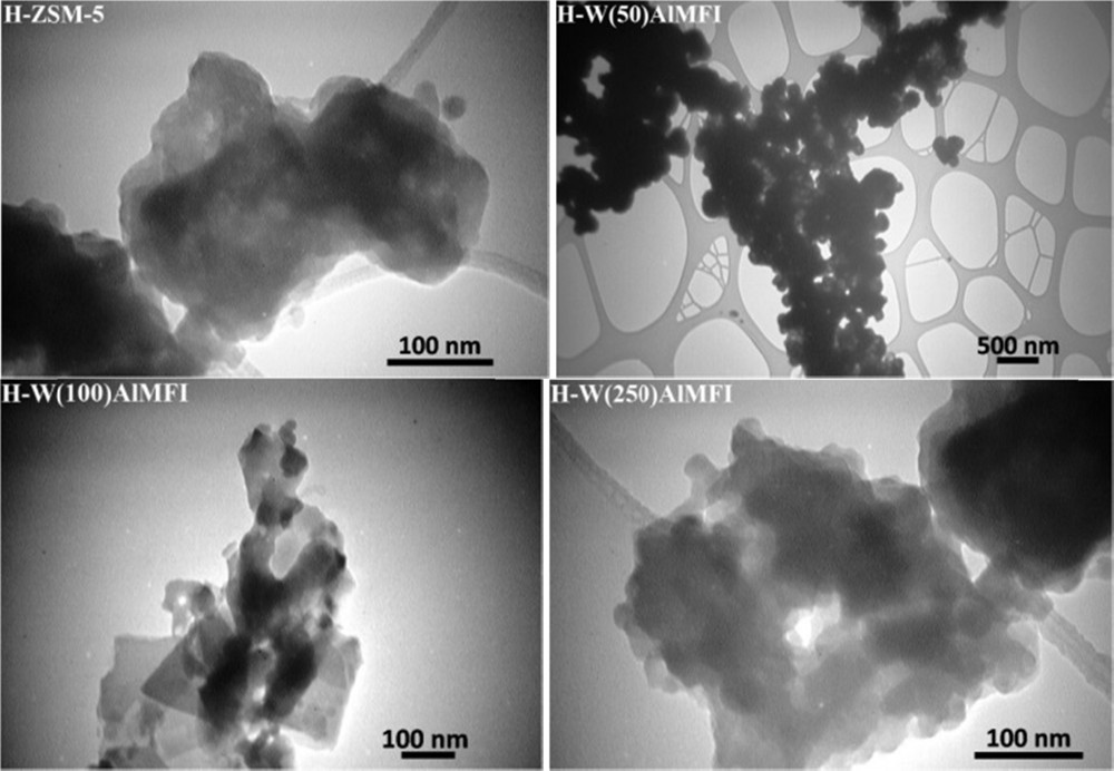
TEM images of the conventional H-ZSM-5 and W-substituted MFI metallosilicates (H-WAlMFI) with different ratios of Si/W.
The particle size distributions of the conventional H-ZSM-5 and H-WAlMFI zeolites were obtained using a DLS technique and are presented in Fig. 8. Larger particles scattered more light than smaller ones and caused fluctuations in the scattered light intensity in relation to their size [56]. The DLS analyses showed that the average particle sizes of the conventional H-ZSM-5, H-W(50)AlMFI, H-W(100)AlMFI, and H-W(250)AlMFI were about 975–1712 nm, 2.62–2.86, 1.38–1.64, and 1.16–1.63 μm, respectively. The DLS analyses demonstrated that the catalyst particles had a relatively normal particle size distribution. It is concluded that the particle sizes were rather uniform.
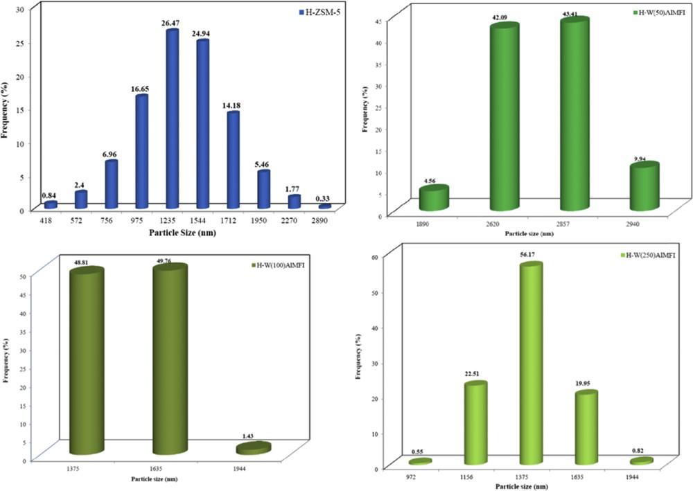
Particle size distribution of the conventional H-ZSM-5 and W-substituted MFI metallosilicates (H-WAlMFI) with different ratios of Si/W.
Fig. 9 shows the N2 adsorption/desorption isotherms. All the H-WAlMFI zeolites and also conventional H-ZSM-5 included a narrow hysteresis loop at the relative pressure of 0.1–1. The catalyst samples revealed weak type IV isotherms, which characterized the dominant microporous with little mesoporous structure. The N2 adsorption/desorption isotherms of the conventional H-ZSM-5 and H-WAlMFI zeolites, especially the H-W(100)AlMFI and the H-W(250)AlMFI demonstrated an increase in the relative pressure range of 0.5 < P/P0 < 1 due to N2 adsorption in the inter particle vacancies [57]. Table 2 shows textural properties of the catalyst samples. The total specific surface area (SBET) of conventional H-ZSM-5 was the highest among the other catalyst samples. The SBET was reduced by substituting the tungsten species in the MFI lattice. The SBET of the H-WAlMFI zeolite decreased more with increase in the tungsten content of that H-WAlMFI zeolite. The total pore volume of H-W(50)AlMFI was lower than that of the others. Furthermore, the mesopore area (SMeso) and the mesopore volume (VMeso) of the conventional H-ZSM-5 were greater than those of H-WAlMFI zeolites. The ideal SMeso and VMeso for production of more propylene in the MTP reaction were sufficiently provided by H-W(250)AlMFI. As shown in Table 4, the highest propylene yield was obtained over the H-W(250)AlMFI catalyst.
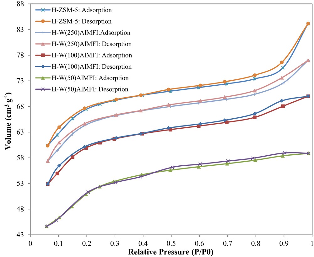
N2 adsorption/desorption isotherms of the conventional H-ZSM-5 and W-substituted MFI metallosilicates (H-WAlMFI) with different ratios of Si/W.
Textural properties of the conventional H-ZSM-5 and W-substituted MFI metallosilicates (H-WAlMFI) with different ratios of Si/W.
| Catalyst | Characteristics | |||||
| SBET (m2 g−1) | SMicro (m2 g−1) | SMeso (m2 g−1) | VTotal (cm3 g−1) | VMicro (cm3 g−1) | VMeso (cm3 g−1) | |
| H-ZSM-5 | 387 | 250 | 137 | 0.13 | 0.08 | 0.05 |
| H-W(50)AlMFI | 298 | 194 | 104 | 0.09 | 0.06 | 0.03 |
| H-W(100)AlMFI | 355 | 235 | 120 | 0.11 | 0.07 | 0.04 |
| H-W(250)AlMFI | 379 | 245 | 134 | 0.12 | 0.08 | 0.04 |
Product distribution and methanol conversion for the conventional H-ZSM-5 and W-substituted MFI metallosilicate (H-WAlMFI) with different ratios of Si/W.
| Catalyst | H-ZSM-5 | H-W(50)AlMFI | H-W(100)AlMFI | H-W(250)AlMFI |
| Methanol conversion% | 99.7 | 99.8 | 100.0 | 100.0 |
| Yield % | ||||
| Methane | 0.9 | 5.9 | 2.0 | 2.9 |
| Ethane | 0.2 | 1.2 | 0.3 | 0.2 |
| Ethylene | 20.5 | 21.2 | 23.7 | 14.2 |
| Propane | 5.3 | 2.1 | 1.7 | 2.1 |
| Propylene | 33.2 | 40.2 | 45.3 | 52.9 |
| Butane | 16.0 | 4.8 | 4.0 | 4.1 |
| Butylene | 15.0 | 16.5 | 17.9 | 17.4 |
| 8.6 | 7.9 | 5.2 | 6.4 | |
| 53.7 | 61.4 | 69.0 | 67.0 | |
| 68.7 | 78.0 | 87.0 | 84.4 |
Acidity of the catalyst samples was investigated using NH3-TPD analyses. Fig. 10 shows the NH3-TPD profiles of the conventional H-ZSM-5 and H-WAlMFI zeolites. The NH3-TPD profiles of the catalysts contained two desorption peaks. Both of them confirmed the acidic sites of the MFI type zeolites [58]. The lower temperature peak at 160–190 °C is related to the NH3 desorption from weak acidic sites and the higher temperature peak at 420–480 °C is related to the NH3 desorption from strong acidic sites. In the MTP reaction, the strong acidic sites accelerate the unwanted reactions such as hydrogen transfer and cyclization reactions. The weak acidic sites improve the formation of initial CC bond via alkylation and methylation reactions, which positively affect the light olefin production. Similarly, the weak acidic sites hinder the side reactions [59,60].
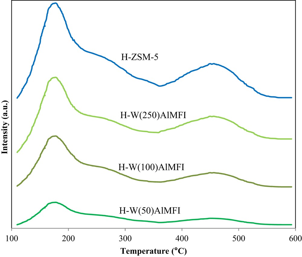
NH3-TPD profiles of the conventional H-ZSM-5 and W-substituted MFI metallosilicates (H-WAlMFI) with different ratios of Si/W.
As shown in Fig. 10, by substituting the tungsten species in the lattice of the MFI zeolite, the strength of acidic sites, especially strong acidic sites, was considerably reduced. For the H-W(50)AlMFI catalyst, the peak that was related to its strong acidic sites was almost eliminated. It is concluded that substituting the tungsten species in the network of zeolites made the strength of acidic sites to be more suitable for conducting the MTP reaction. Adequate strength of acidic sites was provided by the H-W(250)AlMFI zeolite. The H-W(250)AlMFI catalyst maximized the catalytic activity toward more propylene formation.
The ICP-AES technique was used to determine the quantitative elemental composition of the catalyst samples. The suitable agreement between the nominal and measured values of chemical species demonstrated that the framework substitution by W component was successfully conducted through hydrothermal synthesis. The ICP-AES analyses showed that the W heteroatoms were efficiently inserted in the framework of the W-substituted MFI metallosilicates. The insertion of W heteroatoms in the framework of the catalysts certainly affected the propylene yield. The results of ICP-AES analyses are shown in Table 3.
Elemental contents of the conventional H-ZSM-5 and W-substituted MFI metallosilicates (H-WAlMFI) with different ratios of Si/W obtained by an ICP-AES technique.
| Catalyst | Nominal contents in catalyst preparation | Actual contents determined by ICP-AES | ||
| Si/Al | Si/W | Si/Al | Si/W | |
| H-ZSM-5 | 220 | – | 210 | – |
| H-W(50)AlMFI | 220 | 50 | 208 | 47 |
| H-W(100)AlMFI | 220 | 100 | 212 | 95 |
| H-W(250)AlMFI | 220 | 250 | 209 | 243 |
4.2 Catalytic examinations of the MTP process
Thermodynamic studies such as the effect of reaction temperature on methanol conversion to olefins over ZSM-5 zeolite (MFI-type zeolite) has been extensively reported [61,62]. It is commonly identified that methanol conversion and propylene selectivity are improved at higher reaction temperatures (470–500 °C). For MTP process, the reaction temperature should not exceed 550 °C. With respect to the dual-cycle reaction mechanism (Fig. 1), the high reaction temperature provides the activation energy of undesirable reactions such as hydrogen transfer, oligomerization, and aromatization (cyclization) reactions. These side reactions generate side products such as heavy alkanes, cycloalkanes, and aromatics. This issue decreases the propylene selectivity in the MTP reaction. Furthermore, the high reaction temperature causes sintering of the catalyst particles because of the formation of hot spots in the reactor, which reduces the number of active sites in the catalyst sample. According to the literature review, 500 °C is the optimal reaction temperature to maximize methanol conversion and propylene selectivity in the MTP process [21,63,64].
The product yields that were obtained over the conventional H-ZSM-5 and H-WAlMFI zeolites in the MTP reaction are shown in Table 4. As shown in Table 4, substitution of tungsten species in the framework of the MFI zeolites enriched their activity for the production of more propylene than the conventional H-ZSM-5. Among the W-substituted MFI metallosilicates, adequate concentration of tungsten chemical species was obtained by the H-W(250)AlMFI zeolite. The H-W(50)AlMFI and H-W(100)AlMFI generated lower propylene than the H-W(250)AlMFI catalyst in the MTP reaction. The high methane production over the H-W(50)AlMFI catalyst was significant. Also, among the W-substituted MFI metallosilicates, the lowest propylene was produced by the H-W(50)AlMFI zeolite. For all the catalyst samples except H-W(250)AlMFI, the yield of ethylene was higher than that of butylene.
With the use of H-W(250)AlMFI zeolite, methanol conversion and propylene yield were maximized at 100% and 52.9%, respectively. The better catalytic activity and propylene yield for the W-substituted MFI metallosilicate with a nominal Si/W molar ratio of 250 was due to its modified active sites. When the lattice of the MFI zeolite was substituted with tungsten species, the concentration and strength of its acidic sites were reduced. The moderated strength of acidic sites of the W-substituted MFI zeolite could successfully inhibit secondary reactions such as hydrogen transfer, oligomerization, and cyclization reactions. These side reactions led to the formation of undesirable products such as higher olefins, alkanes, and aromatics. The adequate acidic concentration and the most appropriate active sites were presented by the H-W(250)AlMFI catalyst, which are vital for high methanol conversion and yield of enriched propylene.
The catalytic lifetime or TOS examination of the best catalyst (H-W(250)AlMFI) was conducted by using the conventional feed-supply system. As shown in Fig. 11, the methanol conversion reduced at 71 h after the MTP reaction. Reduction of the catalytic activity is attributed to the catalyst deactivation via the coke residues. It seems that the excess carbenium ions in the reaction media led to the formation of high carbon hydrocarbons () and coke depositions by the secondary reactions [10,65].
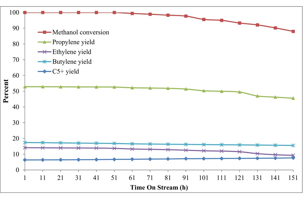
TOS examination over the H-W(250)AlMFI catalyst by using the conventional feed-supply system (syringe pump or micropump, preheater, and mixing chamber).
5 Re-examination of TOS by a novel feed-supply technique
5.1 Analysis techniques of feed composition
Effluents of the novel technique and conventional feed-supply system were condensed 10 h after TOS examinations, and the condensates were analyzed by GC to determine their composition and methanol content. For evaluation of the results, composition of the standard mixture of liquid feed was also analyzed using GC. The standard mixture of liquid feed was the binary solution of methanol and water with 50 mol % of methanol. The different feedstock streams were as follows: a—the condensed outputs of the novel feed-supply technique, which were obtained 10 h after TOS examinations; b—the condensed emissions of the conventional feed-supply system, which were obtained 10 h after TOS investigations; and c—the standard mixture of liquid feed. For GC analyses, 0.1 cm3 of a, b, and c streams were mixed with 0.4 cm3 of n-propanol as an internal standard and then 0.1 cm3 of each sample was injected into the GC. GC analyzer equipped with a CBP-1, capillary column (length 25 m and internal diameter 0.22 mm) and flame ionization detector was used for examination of methanol content. Furthermore, methanol content of the samples a, b, and c was specified by measuring their absorbance using a UV–vis spectrophotometer (WPA light wave S2000) with the wavelength range of 200–850 nm. To obtain the criterion of comparison, absorbance of pure methanol and pure water was also measured using a UV–vis spectrophotometer.
5.2 Analysis of feed composition results
The methanol content of feedstock streams of a, b, and c was determined using GC analyses and UV–vis spectrophotometer. Table S1 and Fig. 12 demonstrate the results of GC technique and UV–vis spectrophotometer, respectively.
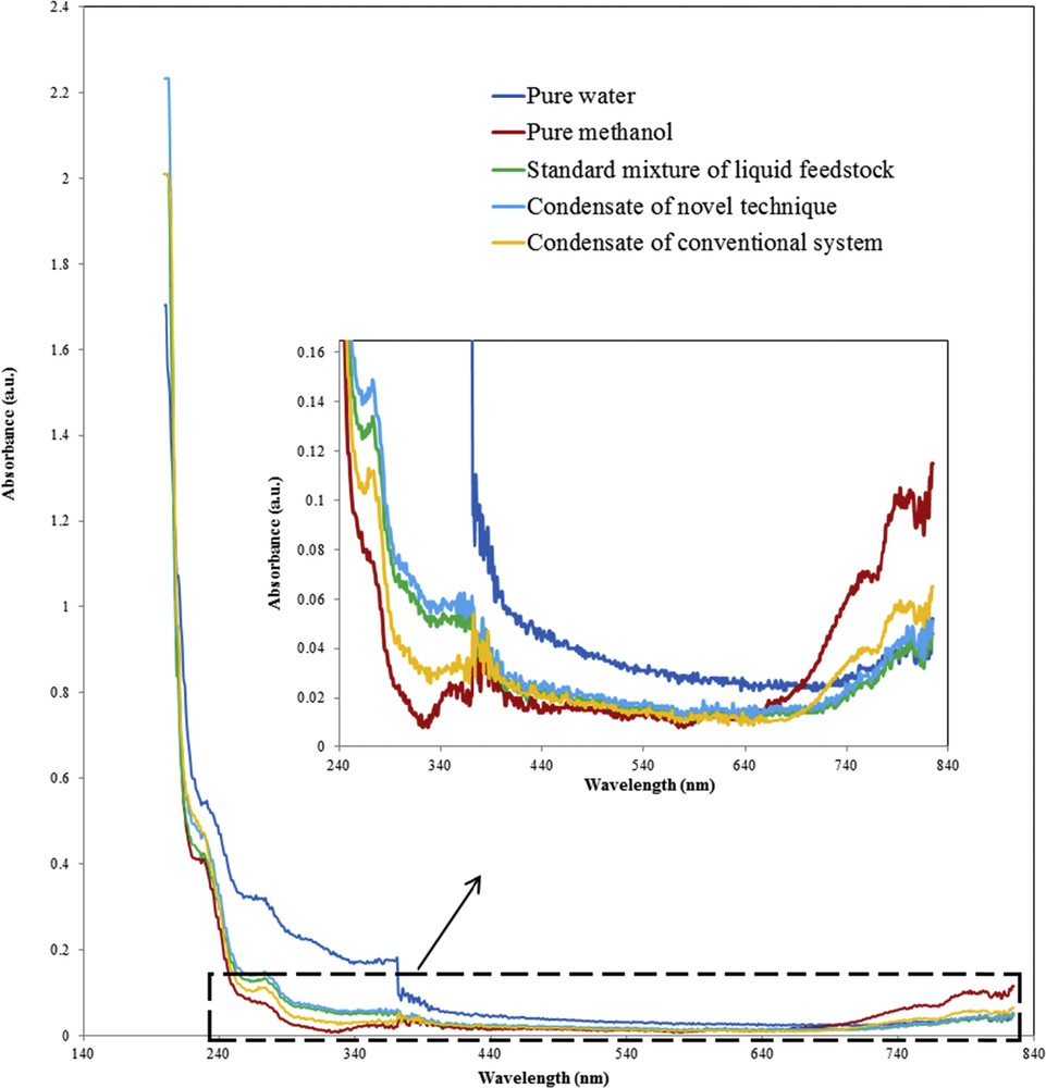
UV–vis spectra of different samples: pure water; pure methanol; standard mixture of liquid feedstock; condensate of novel technique (obtained from the piezoelectric ultrasonic device, 10 h after TOS examination); condensate of conventional system (obtained from syringe pump, preheater, and mixing chamber, 10 h after TOS examination).
Table S1 indicates that methanol content of sample a almost corresponded to methanol content of the sample c, whereas the amount of methanol in the sample b was slightly more than that of sample c. It proves that 10 h after the TOS examinations, composition of the evaporated feed that was obtained from the novel feed-supply technique was almost fixed, whereas the composition of the vaporized feed obtained from the conventional feed-supply system was somewhat changed. Similar results were demonstrated using a UV–vis spectrophotometer. Fig. 12 is a part of whole UV–vis spectra. The profile changes in the whole UV–vis spectra cannot be appropriately distinguished. Therefore, a significant part of the UV–vis spectra was magnified. For more clarification, the whole UV–vis spectra and the significant part of the UV–vis spectra are shown in Fig. S1 of the supplementary material. As shown in Fig. 12, the UV–vis spectra related to the sample b is almost similar to the UV–vis spectra of the pure methanol. This confirms that 10 h after the TOS examinations, the condensate of the vaporized feed, which was obtained from the conventional feed-supply system, relatively contained more methanol than the standard mixture of feed, whereas the UV–vis spectra of sample a was similar to that of the standard mixture of feed. It confirms the better performance of the novel feed-supply technique in comparison with the conventional feed-supply system for provision of feed of the MTP reactor, particularly, 10 h after the TOS examinations.
5.3 Comparison of conventional and novel feed-supply methods
As shown in Table 5, with the use of a novel technique for supply of feed of the MTP reactor, the yield of light hydrocarbons was productively enhanced in comparison with the state where the conventional feed-supply method was used. The propylene yield obtained by a novel feed-supply technique was more than that obtained by the conventional feed-supply system, whereas the yield of heavier hydrocarbons () by the conventional feed-supply system was more than that obtained by the novel feed-supply technique. This issue is probably related to the comparatively high methanol content of feed stream, which was produced by the conventional system. In Section 5.2, the relatively high methanol content of feed produced by a conventional system was demonstrated via GC analyses. The higher methanol content of the MTP feedstock led to creation of more high carbon hydrocarbons, especially . This was also verified by Chen et al. [65]. According to the reaction mechanism of Chen et al. [65], carbenium ions were formed as reactive intermediates during methanol conversion. The higher methanol concentrations of feedstock can produce higher contents of carbenium ions in the reaction region. The higher contents of carbenium ions can be converted to generate more heavy hydrocarbons such as and coke deposition. The reaction mechanism proposed by Chen et al. [65] is shown in Fig. 13.
Methanol conversion and product distribution for the H-W(250)AlMFI catalyst after 1 and 151 h of the MTP reaction.
| Feed-supply method | Results of the MTP reaction after 1 h | Results of the MTP reaction after 151 h | ||
| Conventional system | Novel technique | Conventional system | Novel technique | |
| Methanol conversion % | 100.0 | 100.0 | 88.0 | 96.9 |
| Yield % | ||||
| Methane | 2.9 | 3.2 | 2.3 | 2.7 |
| Ethane | 0.2 | 0.3 | 0.2 | 0.2 |
| Ethylene | 14.2 | 14.7 | 9.3 | 13.3 |
| Propane | 2.1 | 3.0 | 1.9 | 2.6 |
| Propylene | 52.9 | 54.3 | 45.6 | 51.6 |
| Butane | 4.1 | 2.7 | 5.7 | 5.3 |
| Butylene | 17.4 | 16.2 | 15.6 | 14.7 |
| C5+ | 6.4 | 5.7 | 7.7 | 6.4 |
| 67.0 | 69.0 | 54.8 | 64.8 | |
| 84.4 | 85.2 | 70.4 | 79.6 |
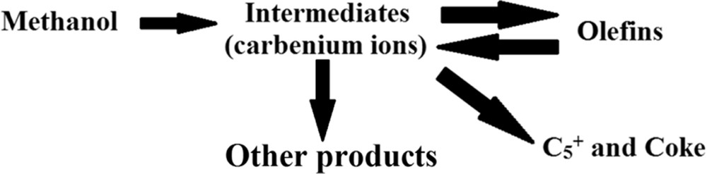
Mechanism of the MTO/MTP reaction proposed by Chen et al. [65].
Fig. 14 shows the results of TOS examination by using a novel feed-supply technique. As shown in Fig. 14, the methanol conversion started to decline 101 h after the MTP reaction. In comparison with TOS examination, by using conventional feed-supply system, deactivation of the H-W(250)AlMFI catalyst was delayed by using the novel feed-delivering method. Probably, it was due to the stable feed composition provided by the novel method. The concentrations of generated carbenium intermediates decrease whenever the feed methanol content is low. The lower content of carbenium ions in the reaction zone speeds up the initial CC bond formation and methylation reaction, which leads to higher amounts of light hydrocarbons, especially light olefins and lower amounts of high carbon hydrocarbons () and coke depositions [10,65–68].
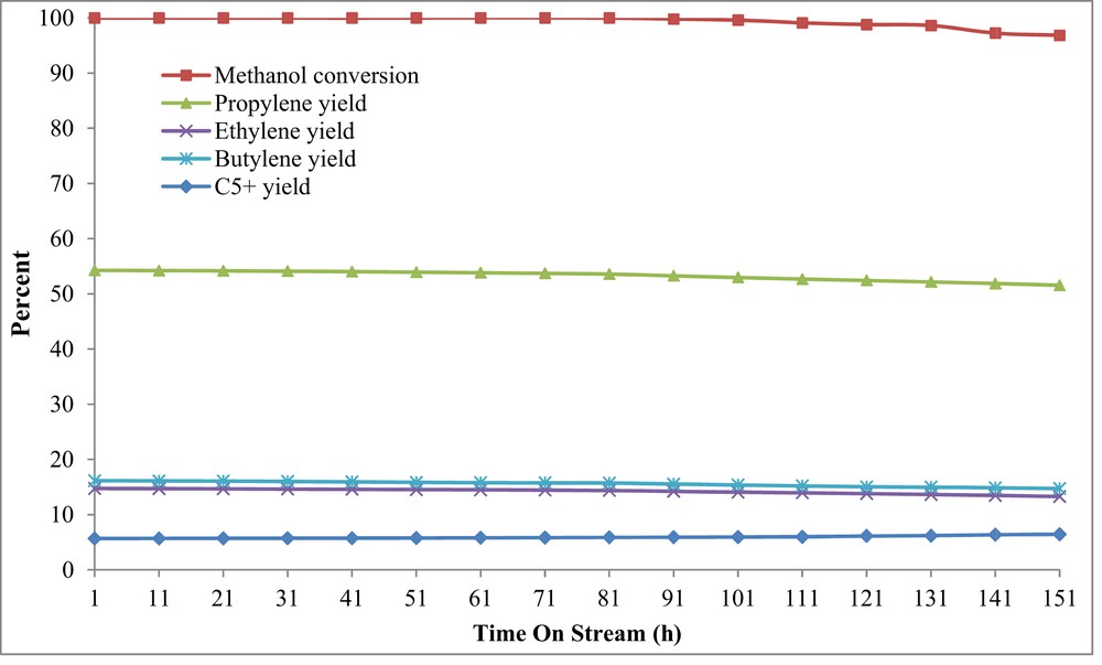
TOS examination over the H-W(250)AlMFI catalyst by using the novel feed-supply technique (piezoelectric ultrasonic device).
Fig. 15 shows the TGA profiles of the H-W(250)AlMFI catalyst used for both novel and conventional feed-supply methods. The TGA curves were divided into two main stages. The first section of weight loss at temperature range of 20–200 °C corresponded to the discharge of physically adsorbed moisture. The second section of weight loss at temperature range of 200–800 °C was a result of the combustion of coke residues. The coke weight fractions that were deposited on the catalyst using the novel and conventional feed-preparing methods were about 5.6% and 8.3%, respectively. The TGA results confirmed the better catalytic stability of the H-W(250)AlMFI catalyst, which was fed by the piezoelectric ultrasonic device. Results of the TGA analysis were matched with the totally constant feed composition, which was delivered using the novel feed-supply technique.
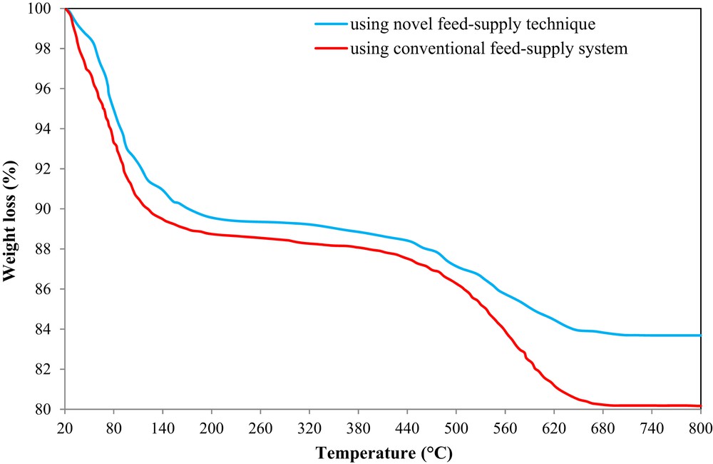
TGA analysis of the H-W(250)AlMFI catalyst used for both novel and conventional feed-supply methods.
Overall, evaluations of the catalyst performance and also the catalytic lifetime examinations in the MTP reactor proved that with the use of a novel feed-supply method, yield of light hydrocarbons, particularly propylene, increased effectively. Therefore, in the MTP process, using the novel feed-supply technique was more applicable than the conventional feed-supply system.
6 Conclusions
In this study, the conventional H-ZSM-5 and W-substituted MFI metallosilicates with different Si/W molar ratios of 50, 100, and 250 (H-WAlMFI) were successfully synthesized using the hydrothermal method. The catalyst samples were appropriately characterized by XRD, FE-SEM, EDX, TEM, DLS, N2 adsorption/desorption, NH3-TPD, ICP-AES, and TGA analyses. The synthesized catalysts were examined in the MTP reaction under optimal operational conditions. Among the metallosilicates, H-W(250)AlMFI had the best performance with regard to activity and propylene yield. Experimental results showed that propylene yield was enhanced (19.7%) by the H-W(250)AlMFI catalyst in comparison with the conventional H-ZSM-5. The catalytic lifetime was re-examined by using a novel technique for supplying the reactor feed. The novel technique used the piezoelectric ultrasonic effect, which miniaturized the MTP process appropriately. The micropump, preheater, and mixing chamber were properly eliminated by using the piezoelectric ultrasonic device. With the use of the novel technique for preparation of reaction feed over the best catalyst (H-W(250)AlMFI), the propylene yield and catalytic lifetime increased to about 1.4% and 30 h, respectively. The better performance of the novel feed-supply method in the MTP process was due to the comparatively lower methanol content of the feed stream of the piezoelectric ultrasonic device and also the feedstock fixed composition.
Acknowledgments
The authors gratefully acknowledge Sahand University of Technology and University of Tabriz for the financial support of the research as well as Iran Nanotechnology Initiative Council for complementary financial support.