

1 Introduction
Recently, a growing interest is developing towards the preparation and use of fluorinated room temperature ionic liquids (F-RTILs). RTILs are a class of compounds that are composed solely of ionic species and are liquid at ambient conditions (this definition differentiates them from ionic liquids (ILs) that, when sharing the ionic nature, are liquids below 100 °C). They have been attracting a great attention in the last couple of decades, as promising media with a wealth of appealing chemical–physical properties, including negligible vapour pressure, high thermal and electrochemical stability, interesting solubility properties towards organic, inorganic and biorelated compounds, and so forth [1–20].
Among the most peculiar RTIL features, their enhanced degree of mesoscopic organization has been attracting great attention, due to the implication that this phenomenology has on a variety of bulk performances. In the last decade, in particular, the integrated use of computational and X-ray/neutron scattering techniques has provided a great support to the unravelling of the intricacies associated with this phenomenon, and nowadays it is well accepted that RTILs are characterized by a distinct level of structural differentiation at a nanometre scale between the polar and apolar moieties that build up their structure [21–79]. In fact, it is now clear that together with typical alternation of ionic species in an onion-like fashion, similarly to conventional inorganic molten salts, such as NaCl, RTILs show a higher level of hierarchical organization that involves the polar versus apolar alternation as a consequence of their mutual tendency to avoid each other. Accordingly, both computations and experimental diffraction techniques evidenced the existence of distinct fingerprints associated with such a hierarchical alternation that has a high impact on properties such as solubility, solvation, diffusive properties, and so forth. In particular, since the first scattering study that is pertinent in this context, it appeared that the mesoscopic organization associated with polar–apolar alternation is fingerprinted by a low Q scattering peak in the X-ray/neutron diffraction patterns collected on RTILs [21]. Useful information on the role played by the alternating polar and apolar domains in RTILs emerged a few years ago, when it became clear that introducing polar moieties in the commonly encountered alkyl side chain would lead to a disappearing of the mesoscopic separation. For example, both in the case of protic [47] and aprotic [32,39,62,63,73] RTILs, a terminal eOH group or the existence of ether group along the side chain leads to the disappearing of the low Q peak that is considered as the fingerprint of the mesoscopic organization.
In this scenario, the introduction of a fluorous moiety into the chemical architecture of an RTIL is likely to introduce analogous effects to those observed when dealing with alkyl chains. Fluorinated compounds are an important class of materials with specific features that make them attractive in the fields of surfactants [80,81], biomedicine [82,83], biphasic (bio)catalysis [84–90] and synthesis [91–96], gas absorption [82,97–99], and so forth. Selectively functionalized compounds with fluorinated moieties might then play a major role in acting as interfaces between fluorous and more conventional solvents aiming at contacting otherwise immiscible media. Accordingly, F-RTILs or fluorinated ionic liquids (FILs), depending on their melting point being less than room temperature or 100 °C, respectively, are attracting great attention due to the interesting properties stemming from their joint ionic and fluorinated nature. A recent review highlighted the relevance of FILs in addressing a wide range of applicative fields including recovery of fluorinated compounds, CO2 capturing and biomedical applications [100]. This report indicated the first reports on FIL synthesis of [101,102] and on the peculiar features of these specific ionic compounds, as compared to their equivalent nonfluorous counterparts. In this framework, with the final goal of developing task-specific ILs with specific activity triggered by appropriate functionalization, Merrigan et al. [102] synthesized imidazolium-based ILs with two side chains (one hydrogenated and another fluorinated). Structural and dynamic properties of such FILs have been studied by different groups using both experimental and computational techniques [103–108]. Other ILs with fluorous moieties have been proposed in the meantime (see, e.g., Refs. [109–112]). Other recent reports have been focussing on ILs with fluorinated anions [9,100,112–127], including some referring to symmetric bis(perfluoroalkanesulfonyl)amide (CxF2x+1SO2)2N anions (hereafter indicated as [IMxx], where x corresponds to the perfluoroalkyl chain length), paired with the diethylmethyl(2-methoxyethyl)ammonium (hereafter indicated as [DEME]) cation. FILs based on such a cation have been investigated in the past [128–134], whereas the symmetric anions bearing long fluoroalkyl chain have been investigated in less detail [123–126].
In this work, we report an overview of our recent activity (see, e.g., Ref. [135]) in the field of structural characterization of F-RTILs, on the basis of experimental (diffraction) and computational techniques that allow accessing mesoscopic morphology details in these compounds.
2 Experimental details
2.1 Chemical details
RTILs based on the DEME cation and IMxx anions, hereafter indicated as [DEME][IMxx], were prepared following the procedure outlined in Ref. [123]. The chemical structure and the atom numbering are reported in Scheme 1.
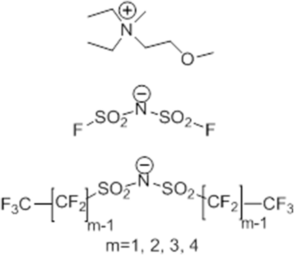
Schematic representation of cation and anions of the F-RTILs described in this work. From top to bottom: DEME cation, IM00 anion and general formula for anions IM11–IM44. Adapted from Ref. [135] with permission from the PCCP Owner Societies.
2.2 X-ray scattering
Small and wide X-ray scattering experiments were conducted at the 11-ID-C beamline at the Advanced Photon Source, Argonne National Laboratory. Measurements were conducted using an X-ray wavelength of 0.11165 Å. CeO2 was used as a calibrant. Samples were inserted into 2 mm diameter quartz capillaries and maintained at ambient temperature during the whole course of the measurements (typically between 20 and 40 min). Empty capillary contribution was subtracted and various corrections including detector sensitivity and Compton scattering were applied using the PDFgetX2 software [136].
2.3 Small-angle neutron scattering
Small-angle neutron scattering (SANS) experiment measurements were performed using the small-angle scattering instrument V4, which is placed in the cold neutron guide of Helmholtz-Zentrum Berlin. The magnitude of the scattering vector is defined as Q = (4π/λ) (sin θ) with λ being the wavelength and 2θ the scattering angle. The measured neutron flux of the V4 is ∼106 cm−2 s−1 for the wavelength λ = 4.5 Å [137]. The scattering data were obtained at a sample to detector distance of 1.0 m, which yields a total momentum transfer range of 0.5 nm−1 < Q < 8 nm−1. For further information regarding the V4 instrument and its resolution the reader is referred to Refs. [137,138]. The samples were placed into circular quartz cuvettes with inner spacing of 1 mm and placed in the beam for measurement. A CD aperture of 13 mm was used for the scattering measurements. The two-dimensional scattering data were reduced to a scattering curve (hereafter indicated as S(Q) versus Q) by the BerSANS software. The raw data were then corrected for transmission, the quartz cell background scattering subtracted and converted to absolute units taking into account the scattering from water [139].
2.4 Computational details
Molecular dynamic (MD) simulations were performed using the GROMACS 5.1.1 package [140,141]. Interactions were described using an all-atom potential [142–146]. The simulations were performed using a cubic box of 1000 ion pairs, where periodic boundary conditions were applied. Force field parameter files and initial configuration were created using the DLPGEN software ([147] and http://webpages.fc.ul.pt/∼cebernardes/dlpgen_prog/Software_dlpgen.html (accessed on 02.03.2017)). The equilibration procedure consisted of several steps, starting from a series of constant number of particles, pressure and temperature (NPT) simulations at high temperatures, using scaled partial charges, followed by progressive lowering of the temperature and increasing of the charges to their final value until an equilibrated system was obtained at 298.15 K and 1 bar, after a 15 ns run. After the mentioned equilibration phase, the system was run for further 15 ns, and then the trajectory of the last 5 ns was saved at a frequency of 1 ps for calculation of the structural properties. The simulations were always checked between the experimental density and the energy profile. For the temperature coupling, we used a velocity-rescaling thermostat [148] (with a time coupling constant of 0.1 ps), whereas for the pressure coupling, we used a Parrinello–Rahman barostat [149] (1 ps for the relaxation constant). The Leapfrog algorithm with a 1 fs time step was used for integrating the equations of motion. Cutoffs for the Lennard-Jones and real space part of the Coulombic interactions were set to 15 Å. For the electrostatic interactions, the particle mesh Ewald summation method [150,151] was used, with an interpolation order of 6 and 0.08 nm of Fast Fourier Transform (FFT) grid spacing. Selected graphs were generated using Matplotlib [152]. Weighted structure factors were computed by using in-house developed software, according to the textbook formulas highlighted in Kashyap et al. [31]. Several analyses were conducted using the latest version of TRAVIS, the software developed by Kirchner and co-workers [108,153–155]. The aggregate analysis was conducted using the software developed by Bernardes and co-workers [156–159].
3 Results and discussion
The [DEME][IMxx] IL series has been studied in the past and a series of chemical–physical properties have been provided for this class of materials [123]. In a more recent contribution, some of us reported structural information on selected ILs, namely [DEME][IMxx] with x = 1 and 4. Here, in the framework of a general account of morphological properties of FILs, we provided a joint experimental and computational description of the microscopic and mesoscopic morphology in [DEME][IMxx] for x = 0–4.
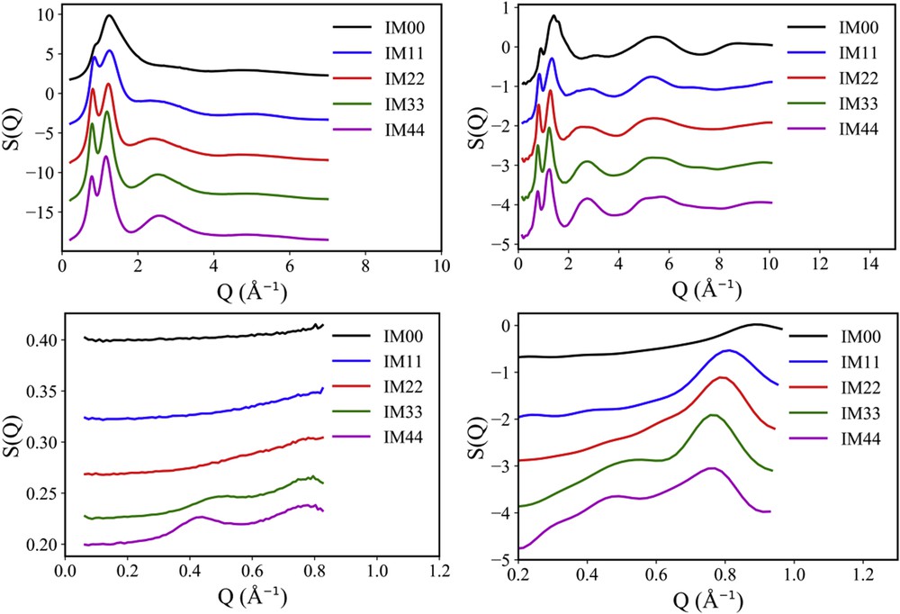
X-ray and neutron scattering techniques are excellent tools to probe structural features in soft matter over spatial scales ranging from fraction of angstrom to several tens of nanometres. The former probe is sensible to electron density contrast, whereas the latter appreciates neutron scattering length density contrast; these densities depend in different ways on the atomic number of the different species in the compounds. X-rays are more sensitive to heavier elements and, for example, hydrogen is hardly observed in X-ray diffraction experiments. On the other hand, due to the way neutrons interact with nuclei, the neutron scattering length density does not depend linearly on atomic weight. Accordingly, even without taking advantage of selective deuteration (i.e., substitution of 1H with deuterium 2H), it is often advantageous to complementarily measure both X-ray and neutron scattering patterns from the same material system. Such a complementary study is particularly useful in the present case of FILs, to probe unequivocally the mesoscopic order in these systems. In Fig. 1, we show the X-ray and neutron scattering patterns from [DEME][IMxx] for x = 0–4.
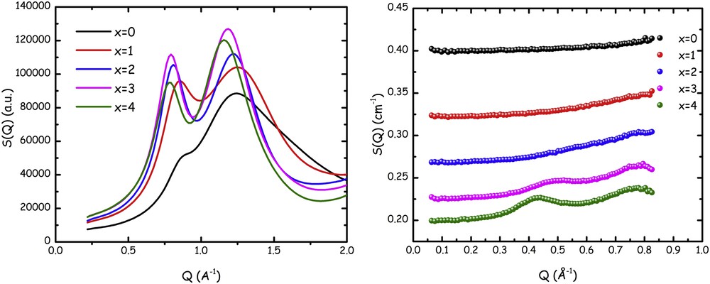
Small–medium angle X-ray (left) and neutron (right) scattering patterns from samples [DEME][IMxx] for x = 0–4 at ambient conditions. The offset among the neutron data sets arises from the different, flat, incoherent background. Adapted from Ref. [135] with permission from the PCCP Owner Societies.
X-ray diffraction data are shown over a larger momentum transfer (Q) range and are characterized by the presence of two peaks in the range 0 < Q (Å−1) < 2: one is centred at ca. 0.8 Å−1 (hereafter this peak will be indicated as falling in position QII) and another falls at approximately 1.3 Å−1 (hereafter this peak will be indicated as falling in position QIII). These are common features in amorphous compounds and in ILs in particular, where peak QIII is associated with structural correlations between nearest neighbours and the lower Q peak (QII) is the fingerprint of correlations due to charge alternation (cation–anion) [33]. What X-ray diffraction data do not deliver in the specific case, as well as in related cases where fluorinated tails are present in the IL anion [121], is a diffraction peak that might fingerprint the existence of polar–apolar alternation between the charged moieties and apolar fluorous tails. Typically in ILs, when an apolar alkyl tail with large enough carbon atoms (e.g., larger than butyl [21] or ethyl [45]) is attached to the charged head of cation or anion, a low Q peak develops at Q ∼ 0.3–0.6 Å−1 (hereafter this peak will be indicated as falling in position QI), fingerprinting the existence of apolar nanodomains with a characteristic size on the order of 1–2 nm, due to the nanosegregation of the apolar tails into the three-dimensional network formed by the coulombic interactions of charged moieties; this corresponds to a characteristic polar–apolar alternation [33], which is ubiquitous in ILs. On the other hand, our previous study on related compounds [121] had shown that upon cooling FILs that are characterized by a featureless low Q part, when low enough temperature is reached the development of a small but not negligible low Q feature occurs, with the formation of peak QI. Such an observation might prompt that upon cooling the sample, if it does not crystallize, it may structurally arrange in such a way that nanosegregation of the fluorous tail can set up, thus leading to the low Q peak. In other words, the mesoscopically unstructured liquid at room temperature might organize upon decreasing temperature to develop the nano-organization typical for polar–apolar differentiated systems.
Neutron scattering (SANS) data, however, seem to indicate a different situation: data shown in Fig. 1 are defined over a narrower Q range (i.e., the one proper for a SANS instrument) and cover the range below Q = 0.9 Å−1, where X-ray data sets are featureless, regardless of the fluorous chain length in the IL's anion. These data, however, together with peak QII centred at ca. 0.8 Å−1 (that appears at the right edge of the accessible Q range) also show the existence of a low Q peak whose position depends in a strong way on the index x, which is a measure of the fluorous chain length. Even at room conditions, evidence of the occurrence of nanosegregation can be detected when using the neutron scattering technique rather than (or better, complementarily to) X-ray scattering technique. The existence of a low Q peak in a Q range on the order of Q ∼ 0.3–0.6 Å−1 and the dependence of its position on the perfluoroalkyl chain length are common features of peak QI in the SANS pattern from ILs that are characterized by nanoscale segregation analogously to the case of conventional ILs [45,72].
By modelling the SANS data using a flat background (accounting for the incoherent scattering) and two Gaussian functions (accounting for peaks QII and QII, centred at Q ∼ 0.3–0.6 and 0.8 Å−1, respectively), one can perfectly describe the experimental data. Fig. 2a) reports the fitted SANS data for the cases of x = 2–4 (where appreciable amplitude for peak QI is experimentally detected). Furthermore, the dependence of the characteristic size associated with the structural correlations leading to the peaks is reported, as given by the Bragg law, D = 2π/Qi, where Qi is the peak position for QI and QII. In Fig. 2b, the D values obtained for the small-angle X-ray scattering peaks QII are not shown but they perfectly overlap the equivalent data set from neutron. The two probes (X-ray and neutron) identify the same structural periodicity for peak QII. On the other hand, only neutrons appreciate the existence of QI. In this figure, the published trends [73,160] observed for the case of QI and QII for dialkylimidazolium bistriflamide ([CxCxmim][IM11]) as a function of x are shown for comparison.
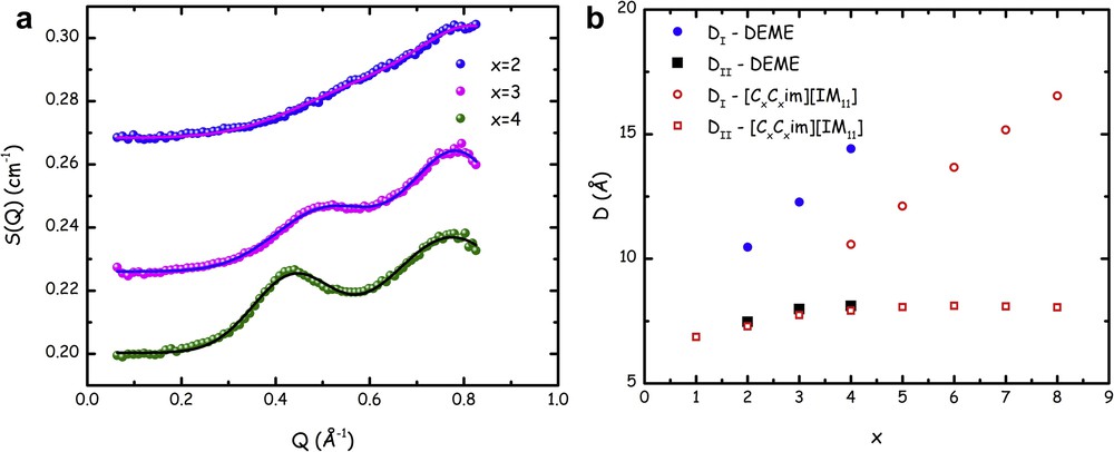
(a) Small–medium angle neutron scattering patterns from samples [DEME][IMxx] for x = 2–4 at ambient conditions. Lines correspond to fits to experimental data in terms of a flat background and two Gaussian contributions accounting for the peaks centred at QI and QII. The offset among the neutron data sets arises from the different, flat, incoherent background. Adapted from Ref. [135] with permission from the PCCP Owner Societies. (b) Fluorous tail length dependence of the characteristic size DI and DII, as obtained using the Bragg law (Dx = 2π/Qx, x = 2–4) from the positions of peaks centred at QI and QII. Together with data for the DEME series, we also report published data from the past studies on symmetric imidazolium cations bearing the anion [IM11] ([CxCxmim][IM11]) [160]. Adapted from Ref. [135] with permission from the PCCP Owner Societies.
These data refer to the D values corresponding to the charge alternation and to the polar–apolar alternation correlations, respectively, where the apolar domains are built up by side alkyl chains connected to imidazolium rings. It is noteworthy that the former correlations nicely match with the trend observed for the case of the [DEME][IMxx] series. Similarly, apart from the difference in the intercept, a linear trend observed for dialkylimidazolium's DI shows a comparable slope than the corresponding data from [DEME][IMxx] series. These analogies in the side chain length indicate strong similarities in the structural organization of these compounds, which is consistent with a scenario where the main driving force is coulombic interactions that maintain polar–apolar alternations. Moreover, the segregation of the apolar moieties (either alkyl chains in the case of imidazolium salts or perfluoroalkyl ones in the case of [DEME][IMxx] series) occurs with organization that is similar as it leads to the same trend in terms of chain length dependence for both alkyl and perfluoroalkyl chains.
The reported data sets indicate that at ambient conditions, FILs are indeed characterized by the existence of an extended level of fluorinated tails' segregation, when fluorous tails are long enough. Although X-ray scattering does not succeed in identifying this occurrence, due to electron density contrast reasons (vide infra), neutron scattering, on the other hand, nicely detects the existence of nanometre scale structural heterogeneities that are the consequences of (fluorous) apolar–polar segregation in the bulk phase.
To obtain an additional insight into this structural organization we have further explored the [DEME][IMxx] series using MD simulations that describe morphology at the mesoscopic level with atomistic resolution.
Nowadays, MD simulation is a powerful tool to access micro- and mesoscopic structural correlations at the atomistic level. Currently, use of up to date desktop hardware solutions allows describing equilibrium organization of simulation boxes with sizes as large as 150 Å over temporal scales of tens of nanoseconds in just 1 or 2 days. This allows access to an unprecedented level of structural insight over systems that just a few years ago were not so easy to access.
Here, we report a description of several structural features related to the fluorous segregation in the [DEME][IMxx] series on the basis of such simulations.
The chosen potential represents a valid compromise in terms of transferability and accuracy in accounting for interactions. Using this potential one can satisfactorily reproduce the experimental density [123] for the [DEME][IMxx] series at 293 K (see Fig. 3). It can be observed that upon increasing the level of fluorination in the anion, the density progressively increases and this trend is nicely reproduced by the potential, although the calculated density systematically shows values higher than those of experimentally observed.
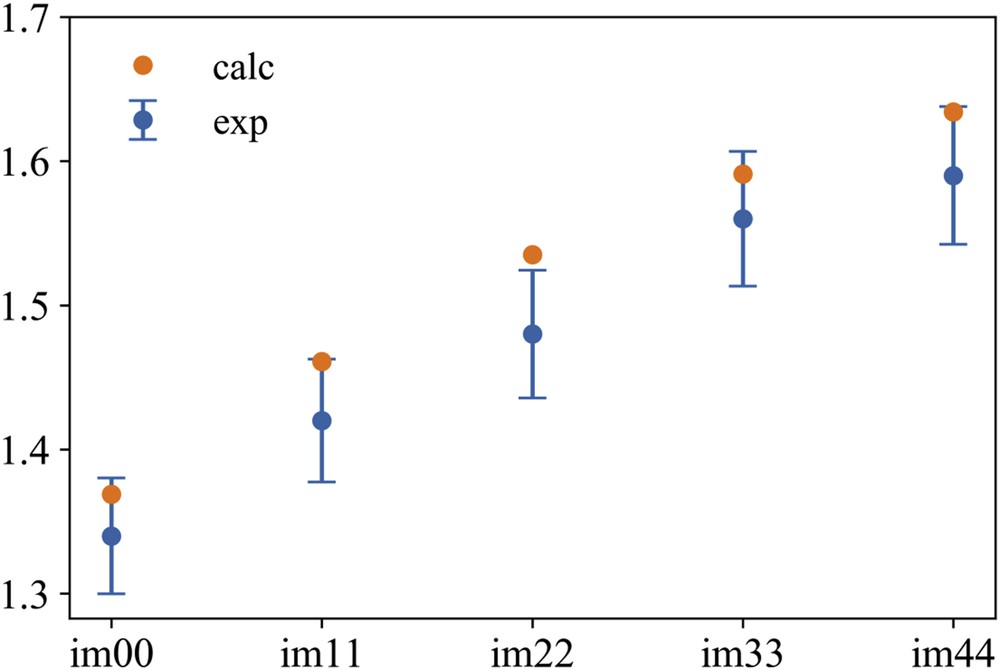
Experimental (from Ref. [123]) and MD computed values of density at 293 K for the [DEME][IMxx] series, x = 0–4. Bars to experimental data refer to 3% tolerance on experimental data collected with a pycnometer.
MD trajectories have also been interrogated on their capability to account for the so far reported X-ray and neutron diffraction features. Needless to say, their capability to detect the fact that neutron scattering appreciates the existence of the low Q peak (QI) that is not evident in X-ray diffraction patterns would provide strong credibility to the capacity of this potential to predict structural features in such a class of materials.
Accordingly, Fig. 4 reports the calculated X-ray and neutron diffraction patterns for the whole members of the [DEME][IMxx] series at 293 K. It can be appreciated that the chosen potential effectively grasps the relevant structural features at microscopic and mesoscopic levels: the existence of peaks QII and QIII in the simulated X-ray diffraction pattern and their relative positions and amplitude is well accounted for. Moreover, simulated X-ray patterns do not show evidence of the existence of peak QI. On the other hand, computed neutron patterns nicely describe the slight shift towards larger Q values of the position of peak QII and perfectly account for the existence and position of peak QI, which is the main feature, that we aim at describing in this work. Overall, we can then conclude that the chosen potential is correctly accounting for structural properties and, in particular, for mesoscopic structural correlations occurring in the [DEME][IMxx] series. MD trajectories obtained with this potential choice can then be reliably interrogated for further details that can be useful to describe the structural organization of fluorous tails in this class of ILs.
Comparison between experimental (left panel) and MD calculated X-ray (top panel) and neutron (bottom panel) diffraction patterns for the whole members of the [DEME][IMxx] series at 293 K. In the case of neutron scattering data, the offset of experimental data is due to the different incoherent background. In the case of computed data, it is arbitrary chosen for the sake of comparison. Adapted from Ref. [135] with permission from the PCCP Owner Societies.
Ionic species in the bulk phase of the [DEME][IMxx] series are mutually structurally correlated. Intuitively, the main driving force to correlations is coulombic forces that tend to attract unlike species and repel moieties with the same charge; this is reflected by pair distribution functions (pdfs) between the cation and anion. To describe this, we arbitrarily identify the nitrogen in the cation and the one in the anion as the reference atoms to investigate interionic correlations and Fig. 5 shows such pdfs. The multishell coordination of cations around a reference cation can be appreciated: up to three different coordination shells can be observed at 8, 11 and 17 Å, approximately, without substantial differences between the different salts apart from the first member of the series (IM11), which is characterized by a slightly expanded first coordination shell as compared to other members of the series. Analogously two anion–anion coordination shells can be detected at ca. 10 and 18 Å, where again the [IM11] member differentiates itself from other members as presumably due to smaller anion sizes, closer anion–anion contacts can be achieved than for larger anions. A more systematic trend can instead be appreciated by exploring the cation–anion coordination. In this case, the first coordination shell is composed of two subshells, one centred at ca. 5 Å and the other at ca. 6 Å. For both shells, the peak amplitude grows with an increasing anion size. Moreover, the second shell gets closer and closer to the reference ion with a growing anion size. Overall, upon increasing the anion chain length one observes a progressive (a) approaching of cation–cation correlations and (b) departing of anion–anion correlations. In the bottom panels of Fig. 5 representative g(r)'s for NcNc, NcNa and NaNa for the cases of [IMxx] with x = 1 and 4 are shown. The typical onion-like organization is observed with NcNa having its first peak at the shortest distance and the similar sign g(r)'s having peaks when opposite sign g(r) has its minima. In the case of [IM44], it emerges clearly how anion–anion correlations get larger in spatial extent, whereas cation–cation correlations get closer in the case of [IM11].

MD-computed pdfs between specific relevant atomic sites (nitrogen atoms in the cation and anion, Nc and Na, respectively) for the [DEME][IMxx] series (x = 1–4) at ambient conditions (top). For the sake of comparison NcNc, NcNa and NaNa are reported in the same plot for the case of [DEME][IM11] (bottom, left) and the [DEME][IM44] (bottom, right) samples.
The [DEME] cation is composed of moieties that bear a non-negligible local charge on each methylene or methyl group. Accordingly, it cannot be considered as composed of polar and apolar moieties, but it is rather a whole polar entity. Apart from the short extension of the methyl and ethyl moieties, this is also a consequence of the existence of an ether group along the long chain in [DEME]. The presence of such ether moieties has been shown to provide specific features to cations bearing them that can be rationalized considering that the usual polar versus apolar dichotomy usually found in IL cations does not occur in the present cation [32,39,62,161,162]. This is at odd with the situation encountered with the [IMxx] anions, especially for x = 2–4. In these latter cases, difluoromethylene and trifluoromethyl groups bear a null charge that characterizes them as apolar moieties. On the other hand, the N(SO2)2 moiety bears a negative charge that defines the polar portion of the ion. The situation is different in the cases of [IMxx] with x = 0 and 1. In the latter case, a small negative charge is localized on the CF3 groups and in the former case the whole anion can be considered as a whole charged species, with no apolar portion. This somehow introduces a differentiation between the members of the [DEME][IMxx] series: those with x = 2–4 are ILs that are characterized by the coexistence of polar and apolar moieties. The same differentiation does not exist in the cases of x = 0 and 1. Although the cation can be described as a whole polar species, anions can be considered as amphiphilic compounds, with a central charged (polar) portion and for the case of longer side chains, two apolar moieties. Such a situation straightforwardly leads to a spatial differentiation between charged and neutral moieties (polar and apolar ones). To visualize such a structural scenario, Fig. 6 shows arbitrarily chosen simulation snapshots from [DEME][IMxx]. In all cases (n = 0–4), F, CF2 and CF3 moieties have been depicted in green whereas other species are depicted in red. This figure in a straightforward way shows that although perfluorochains in the case of n = 2–4 tend to cluster forming small domains that eventually merge, percolating across the simulation box, this is not the case for n = 0 and 1 where the essentially polar nature of the species leads to a homogeneous distribution of cations, anions and the moieties building them up, without a differentiation of fluorous moieties from other polar moieties. This situation is explained in Fig. 7, where the coordination of the terminal trifluoromethyl group and the sulfonyl oxygen around the reference cation's nitrogen is shown, as a function of the anion chain length. One notices that terminal trifluoromethyl groups (CFT) approach closer to the cation's reference when the perfluoro chain is shorter. On the other hand, the sulfonyl oxygen can better solvate the cation's reference when the chain is shorter. The former observation is consistent with the fact that [IM11]'s CFT bears a negative charge that other CFTs do not possess. It is then reasonable that it tends to approach the positively charged cation. Analogously, the progressive localization of net negative charge on the sulfonyl group, when the perfluoro chain gets longer, explains why larger anions can more efficiently use their sulfonyl groups to coordinate positively charged moieties.
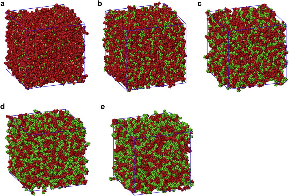
Representative arbitrarily chosen simulation snapshots from [DEME][IMxx] (x = 0–4, from (a) to (e), respectively). In all cases, F, CF2 and CF3 moieties have been depicted in green whereas other species have been depicted in red.

MD-computed pdfs depicting the coordination of the terminal CF3 group (CFT) (left) and the sulfonyl oxygen (Oan) (right) around the reference cation's nitrogen (Ncat) as a function of the anion chain length, for the [DEME][IMxx] series (x = 1–4), are shown.
The coordination of a reference cation by anions can be better understood by inspecting the spatial distribution functions (sdfs) referred to the central cation and different atomic species belonging to the anion. In Fig. 8, such sdf is shown, where the coordination shells of anion's nitrogen (blue), oxygen (red) and fluorine (green) atoms are reported for the two extreme examples of [DEME][IMxx], with x = 0 and 4 (left and right panels, respectively).

MD-computed sdfs reporting the coordination shells of anion's nitrogen (blue), oxygen (red) and fluorine (green) atoms around a central cation, for [DEME][IMxx], with x = 0 and 4 (left and right panels, respectively).
The isovalues for Fig. 8 (both left and right panels) have been chosen to be the same for each atomic species so that direct comparison can be made between the two anions. A profound difference immediately emerges in the way that small and large anions coordinate with the central reference cation. In particular, it can be noticed that [IM00] tends to coordinate the central cation in a doughnut organization around the axis identified in the long CH2CH2OCH3 chain. This behaviour is analogous to the one shown for [IM44]. The two anions, however, differ in the fact that the small one is capable of coordinating the cation also along the above mentioned axis: one coordination lobe is hidden by other coordination clouds, but the front lobe along the ethylmethoxy chain facing to the methyl group is clearly visible and has no corresponding counterpart in the case of [IM44]. This situation clearly resembles the findings of Siqueira and Ribeiro [161] on a related compound, namely dimethyl-ethyl,2-methoxyethylammonium [IM11] ([DMEE][IM11]), where an average number of 6.6 (6.3) anions were found to coordinate in the first shell a central cation at 350 (400) K. In our present case, the corresponding quantity at 298 K amounts to 6 and 4 for the case of [IM00] and [IM44], respectively. These authors rationalized these figures proposing that five [IM11] coordinate the cation in an octahedral-like coordination scheme, where one of the sites remains unoccupied due to the asymmetry introduced by the ethylmethoxy chain. We observe similar situation for the case of [IM00] and, as a matter of fact, Fig. 8 (left) shows the existence of the mentioned shifted lobe that coordinates the cation at a further distance located at the end of the ethylmethoxy chain. The introduction of long fluorous tails in the anion leads to sterical hindrance between neighbour anions that disfavour an almost ideal coordination in an octahedral-like coordination scheme. Accordingly, the coordination number is substantially lower and one can appreciate that no anion coordination occurs close to the end of the ethylmethoxy chain (Fig. 8, right). In this respect, the growing size of anions, due to an increase in the fluorous chain length, introduces strong elements of deviation from the quasi-octahedral coordination found in members with smaller anions.
Concerning the anion coordination, Fig. 9 shows the sdfs with a reference anion and the first coordination shell of cation's nitrogen around it. It appears clearly that in agreement with the recent results observed by Wu et al. [125] for ILs based on [IM00], [IM11] and [IM22], the former anion is coordinated by the cation in a doughnut-like way around the sulfonyl oxygen atoms but also due to its highly polar nature (and lack of amphiphilic nature) at the terminal SO2F moieties. On the other hand, anions with longer fluorous tails do not show the latter kind of coordination, only the doughnut-like coordination is found and the fluorous tails remain uncoordinated by the cation.
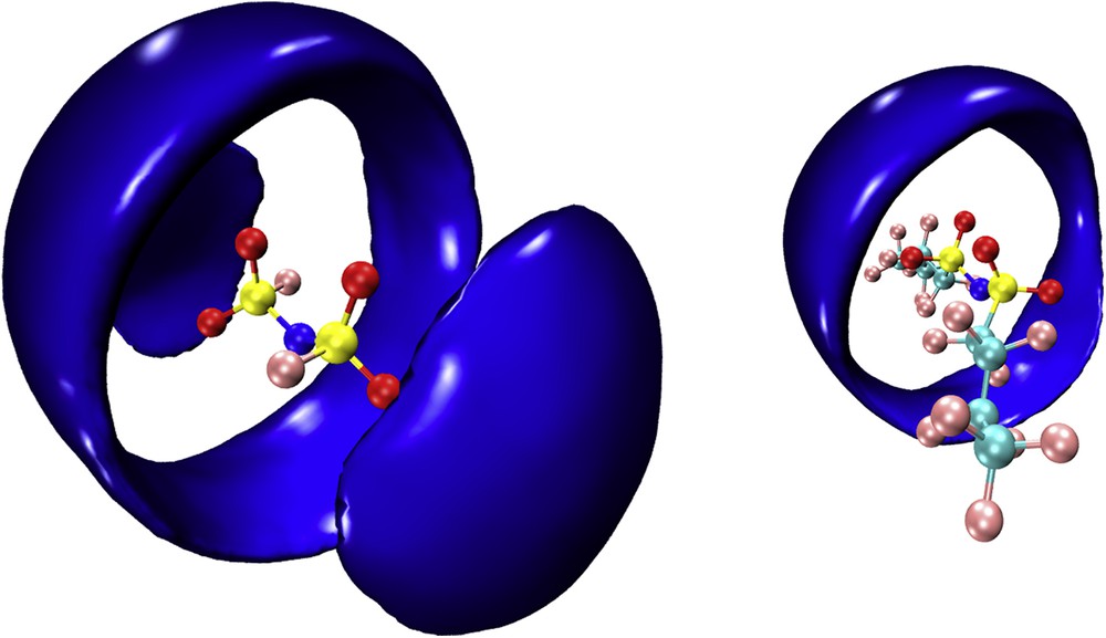
MD-computed sdfs reporting the coordination shell of cation's nitrogen (blue) around a central anion, for [DEME][IMxx], with x = 0 and 4 (left and right panels, respectively).
This observation leads us to explore the nature of fluorous tail organization in this class of ILs.
Fig. 10 reports the pdfs relative to terminal trifluoromethyl groups' self-correlations (CFT–CFT). It emerges that when increasing the perfluoroalkyl chain length, the extent of methyl groups' clustering tends to increase: low levels of clustering are detected for [IM11] (the amplitude of the peak centred at ca. 5 Å is approximately equal to the uniform density (g(r ∼ 5 Å) ∼1)), whereas the amplitude grows for the case of [IM22] and eventually saturates to a value of approximately 2 for [IMxx], when x = 3 and 4. We stress that these pdfs monitor the tendency of fluorous moieties to cluster. This and the consequent formation of fluorous domains can be further appreciated by inspection of the arbitrarily chosen simulation snapshots that are shown in Fig. 6. Either isolated fluorine atoms or very small clusters of trifluoromethyl groups can be detected for [IMxx], when x = 0 and 1, whereas large extent domains (getting the larger the longer the fluorous chain) can be observed with growing x. Such an effect has been monitored using a statistical tool that directly explores the occurrence of aggregates and provides an estimate for their average sizes [156,158,163]. Fig. 11 reports the distribution of sizes (number of monomers) for the [DEME][IMxx] series with x = 1–4. It can be appreciated that trifluoromethyl groups in the case of x = 1 form very small clusters with a high percentage of either isolated groups, dimers or trimers, and only a tiny percentage of more pentamers is detected. Already shifting to x = 2, one appreciates the existence of larger clusters of fluorous tails with size distribution extending up to ca. 30–40 monomers. Such a distribution includes even larger aggregation numbers for the case of x = 3 and in the case of x = 4, together with a population of small clusters, it can be detected a population of very large clusters composed of hundreds of monomers. It is noteworthy that this analysis tool indicates the existence of discrete clusters for any fluorous chain length. As this length has the upper limit of nonafluorobutyl, this finding is in agreement with the recent observations from Vieira et al. [117], but somehow at odd with the behaviour observed by Shimizu et al. [164], where a transition is observed between discrete clusters and percolating organization of the fluorous domains.

Pdfs relative to terminal trifluoromethyl groups' auto correlations (CFT–CFT) for the series [DEME][IMxx] (x = 1–4).
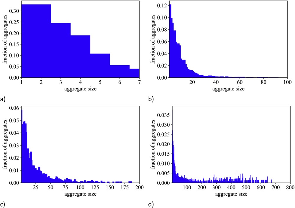
MD-computed distribution of fluorous moieties' cluster sizes (number of monomers) for the [DEME][IMxx] series with x = 1–4 (from panel (a) to (d), respectively).
The role of (fluorous) apolar versus polar alternation in determining the experimental low Q (neutron) diffraction feature can be further explored using the decomposition formalism proposed by Margulis and co-workers in a series of articles [31–33,114]. Fig. 12 shows the decomposition of experimental neutron diffraction patterns in terms of polar and apolar contributions for the [DEME][IMxx], with x = 2, 3 and 4. It clearly appears that the differentiation of ionic species into apolar (all the CF2 and CF3 moieties) and polar ones leads to the development of neutron scattering contributions for polar–polar, polar–apolar and apolar–apolar terms that, once properly combined, lead to the development of the low Q peak, QI. These plots, similarly to other published examples [31–33,114], show that structural correlations between similar polarity moieties (polar–polar (red lines), apolar–apolar (green lines)) lead to a diffraction peak at position QI. On the other hand, structural correlation between moieties with different polarities (polar–apolar (blue lines)) are characterized by an out of phase correlation that leads to a negative amplitude peak at position QI. The experimental pattern is the combination of these contributions and accordingly there is an overall peak at position QI, arising from the polar–apolar alternation. In the same figure, as a representative case, we also show the equivalent plot for the case of [DEME][IMxx], with x = 4, where the X-ray diffraction pattern is considered. As already mentioned, experimental X-ray data are not characterized by the presence of peak QI, despite the now clear existence of fluorous domains segregated in the otherwise homogeneous polar matrix. The present plot clarifies this puzzling situation: it is clear that the in-phase polar–polar (red lines), apolar–apolar (green lines) and the polar–apolar (blue lines) correlations are still present, only due to contrast reasons (i.e., the weight of each component that depends on the electron density of each moiety), their sum leads to a quasi-zero total contribution, despite we stress again the existence of the characteristic periodicity of the polar–apolar alternation.
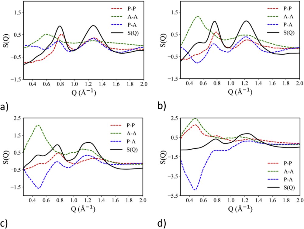
(a–c) Decomposition of the experimental neutron scattering pattern in terms of polar–polar, apolar–apolar and polar–apolar contributions for [DEME][IMxx], with x = 2–4. Adapted from Ref. [135] with permission from the PCCP Owner Societies. (d) Decomposition of the experimental X-ray scattering pattern in terms of polar–polar, apolar–apolar and polar–apolar contributions for [DEME][IMxx], with x = 4.
4 Conclusions
Overall, the wealth of experimental and computational evidence provided to describe the structure of the [DEME][IMxx] series, with x = 0–4, converges in providing a morphological scenario where a polar charged matrix composed by the cation and the sulfonyl moiety of the anion embeds discrete clusters formed by segregated fluorous tails.
This work highlights the important role played by the synergy between X-ray and neutron scattering techniques as well as the state-of-the-art MD simulations. Due to contrast reasons, X-ray scattering does not appreciate the existence of such discrete fluorous domains. The latter are, however, easily detected by neutron scattering techniques. The technique allows detecting the fluorous chain length dependence of the segregated clusters that follow a linear trend, similarly to the case of alkyl side chains in other compounds, including ILs.
The existence of segregated fluorous domains that might lead either to discrete clusters or to a percolating network is then proposed to be ubiquitous in the case of FILs bearing sufficiently long fluorous tails. Neutron scattering experiments suggest the existence of the specific diffraction feature at low Q already when dealing with the [IM22] anion that corresponds to a pentafluoroethyl group. This is somehow resembling the behaviour observed in the case of alkylsulfate-based ILs, where an ethyl chain connected to the anion is sufficient to identify a low Q diffraction peak that fingerprints analogous alkyl domain segregation [59,165].
The behaviour observed in ILs is a direct consequence of their inherently amphiphilic nature. Either alkyl or perfluoroalkyl chains are both apolar moieties that tend to segregate from the polar matrix formed by the charged moieties interacting through coulombic or hydrogen bonding interactions.
Such a highly compartmentalized morphology at the mesoscopic scale is envisaged to confer specific features to ILs impacting as wide fields as solubility of different, mutually incompatible substances, catalysis, separation and synthesis and so forth.
Acknowledgements
A.T. acknowledges Dr. B. Aoun for his kind and competent assistance in using beamline 11-ID-C at Advanced Photon Source (APS). This research used resources of the APS, a U.S. Department of Energy (DOE) Office of Science User Facility operated for the DOE Office of Science by the Argonne National Laboratory under Contract No. DE-AC02-06CH11357. This work was partly supported by the Japan Society for the Promotion of Science (JSPS) KAKENHI Grant Numbers JP22685015 and JP25288041. A.T. thanks Helmholtz-Zentrum Berlin for the allocation of neutron beamtime. This work has been supported by the University of Rome Sapienza Project: Microscopic and mesoscopic organization in ionic liquid-based systems (RG11715C7CC660BE).