


 CC-BY 4.0
1. Introduction
In order to meet the growing demand for energy, it is essential to promote renewable means of production and transformation. Hydrogen is a promising candidate that can be sustainably produced from water [1] via a green electricity–driven water splitting reaction [2, 3] and used as an energy vector [4, 5]. Unfortunately, the cost competitiveness of these systems suffers in part from low energy efficiency due to the high overpotential required to initiate the Oxygen Evolution Reaction (OER), that oxidizes water to oxygen [6, 7]. Reducing the overpotential requires the use of an electrocatalyst to lower the energy barrier associated with the formation of reaction intermediates [8, 9, 10]. Noble metal catalysts such as RuO2 and IrO2 are the reference materials as OER electrocatalysts but the scarcity of these metals and their prohibitive cost make large-scale industrialization impossible in the future.
In this way, the scientific community has focused on the development of 3d-metal-based catalysts and this research has highlighted some iron-based materials as the best OER catalysts in alkaline electrolytes reported in the literature, such as Ni–Co–Fe layered double hydroxides (LDH) [11, 12, 13]. Although the role of iron in the OER mechanism is not yet clear, its presence seems essential to further improve the electrochemical performance [14, 15, 16].
While many works in the literature focus on the determination of the best cationic composition, which seems to lean towards the Co/Ni/Fe association [17], few studies are devoted on the modification of the anionic part, which is nevertheless of interest [18, 19]. Fluorine, the most electronegative element in the periodic table, is of particular interest to modulate the electronic structure of neighboring metals thanks to its strong inductive effect. As a result, the metal active site is electron-depleted and easily hydroxylated in highly alkaline electrolytes [20], which is the first step of the OER mechanism [9, 21]. The first transition-metal fluoride reported in the literature as an OER catalyst in alkaline media is a nanostructured mixed Co–Ni–F material, which exhibits a low overpotential of 300 mV at 10 mA⋅cm−2, outperforming the reference material IrO2 [22]. Pei et al. reported the fluorination of Fe–Co Prussian blue analog nanocubes, which resulted into 3D porous Fe–Co–F nanocubes reaching an overpotential of 250 mV at 10 mA⋅cm−2 with a Tafel slope of 39 mV⋅dec−1 [23]. Subsequently, Pei et al. fluorinated NiFe-LDH to further enhance its OER activity [24]. This study shows that a suitable fluorination temperature changes the initial morphology of NiFe-LDH and leads to the formation of fluorides, resulting in an excellent OER activity with an overpotential of 225 mV for a Co-free material, close to the best performance obtained with trimetallic NiCoFe-LDH.
In the same direction, some studies aim to combine oxygen and fluorine anions in 3d-materials and conclude that fluorine incorporation into transition metal oxides improves OER performance [25, 26, 27]. Recently, a mixed Co/Fe oxyfluoride with the formulation Co0.5Fe0.5O0.5F1.5 has been synthesized and further patented by us [28]. This material, synthesized by thermal decomposition of the hydrated fluoride CoFeF5(H2O)7, exhibits excellent OER performance and long-time stability in highly alkaline media [29]. Substitution of the Co2+ ions by Ni2+ resulted in better OER performance and stability, with an optimum for the Co0.25Ni0.25Fe0.5O0.5F1.5 composition [30].
In a sustainable framework, this work presents the reduction of Co2+ amount in Co0.5Fe0.5O0.5F1.5 by substitution with Fe2+ following the same method as before [30]. Different (Co1−xFex)2+FeF5(H2O)7 compositions (0 ⩽ xtheo ⩽ 0.75) have been synthesized and structurally characterized. The thermal behavior of these materials is studied by High Temperature X-ray Diffraction (HT-XRD) and Thermogravimetric Analysis (TGA) to understand the decomposition mechanism leading to Fe-enriched oxyfluorides. The phases obtained from the calcination of (Co1−xFex)2+FeF5(H2O)7 were tested as catalysts for OER to evaluate the cationic Co2+/Fe2+ substitution on the electrocatalytic performance.
2. Results and discussion
2.1. Synthesis and characterization of (Co1−xFex)2+Fe3+F5(H2O)7 (0 ⩽ xtheo ⩽ 0.75) precursors
Iron-rich hydrated fluorides (Co1−xFex)2+Fe3+F5(H2O)7 with theoretical compositions xtheo = 0, 0.25, 0.5 and 0.75 have been synthesized by coprecipitation with aqueous hydrofluoric acid (HF) as fluorinating agent. The substitution of Co2+ ions by Fe2+ is possible only by preventing the oxidation of Fe2+ to Fe3+; it is achieved by dissolving Co2+ and Fe3+ salts together in HF and Fe2+ salt separately in methanol. The obtained polycrystalline powders, which turn yellow depending on the Fe2+ amount (Figure S1), were first analyzed by powder X-ray diffraction (PXRD). PXRD diagrams of the (Co1−xFex)2+Fe3+F5(H2O)7 series show that the structures are isostructural with the reference (Co2+Fe3+F5(H2O)7, x = 0), and indexed in the triclinic P − 1 space group (Figure 1a). Their crystalline structure consists of isolated [Fe3+F5(H2O)]2− (brown) and [(Co/Fe)2+(H2O)6]2+ octahedra (beige) (Figure 1a, inset). As the radii of the Co2+ and Fe2+ ions are close, 0.742 Å and 0.781 Å, respectively [31], only a subtle shift of X-ray peaks is observed.
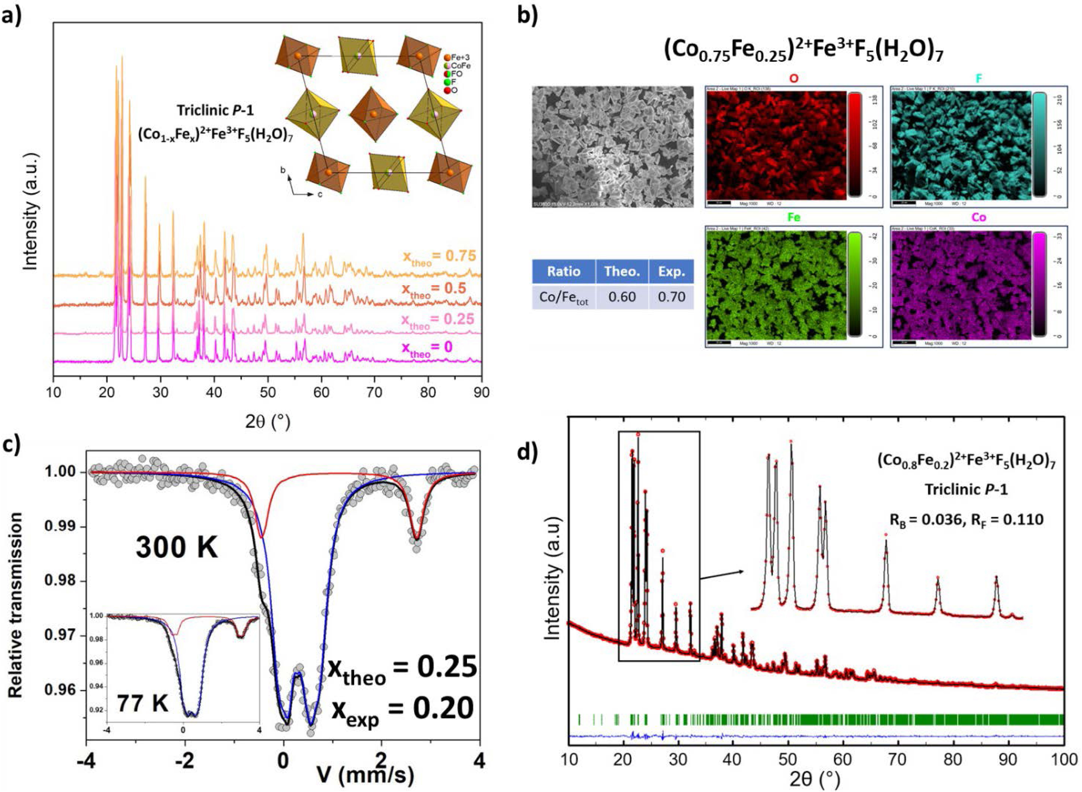
(a) (Co1−xFex)2+Fe3+F5(H2O)7 PXRD diagrams with the corresponding [100] projection of the structure, (b) SEM images of the microcrystalline powder of (Co0.75Fe0.25)2+Fe3+F5(H2O)7 and elemental mapping of each metal belonging to the hydrated fluoride phase, (c) 57Fe Mössbauer spectra at 300 K and 77 K of (Co0.75Fe0.25)2+Fe3+F5(H2O)7, (d) Rietveld refinement of (Co0.8Fe0.2)2+Fe3+F5(H2O)7 structure.
EDX-coupled SEM confirms the crystallinity of particles with sizes in the range of tens of micrometers, together with a homogeneous distribution of 3d cations (Figures S2–S5), as illustrated in Figure 1b, corresponding to the composition (Co0.75Fe0.25)2+Fe3+F5(H2O)7. The experimental values of the n(Co/Fetot) ratio are consistent with the substitution of Co2+ ions by Fe2+ ions in the triclinic phase (Co1−xFex)2+Fe3+F5(H2O)7. However, the experimental n(Co/Fetot) ratio for compositions containing Fe2+ is systematically higher than the theoretical ones, indicating a lower Fe2+ content, in contrast to Fe2+-free Co2+Fe3+F5(H2O)7 where the value fits perfectly. Thus, despite the precautions taken during synthesis, a small amount of Fe2+ is probably oxidized to Fe3+ in solution.
57Fe Mössbauer experiments were then performed to gain insight into the iron environment and on its valence state. All Mössbauer spectra of the (Co1−xFex)2+Fe3+F5(H2O)7 series were collected at 300 K, while one was obtained at 77 K (Figure S6), shown here in Figure 1c for a theoretical value of xtheo = 0.25. At 300 K they consist of a quadrupolar structure resulting from two different doublets, which can be unambiguously attributed to the presence of Fe2+ and Fe3+ species, except for the composition xexp = 0 where the quadrupolar doublet is attributed to Fe3+ species only. Different fitting models with 2, 3 and 4 quadrupolar components were considered. The table in Figure S6 shows the mean refined values of the hyperfine parameters: the isomer shift and quadrupolar splitting values are quite independent of the cationic composition, but their respective absorption regions are strongly dependent on the cationic composition. It is important to note that these values are the same at 77 K, suggesting that the Lamb–Mössbauer factors are similar for the two Fe species. In addition, the values of isomer shift suggest that the Fe3+ ions are on average located in octahedral FeF5O units, while the Fe2+ ions are located in octahedral FeO6 units. The 57Fe Mössbauer data exploitation allowed quantifying the proportion of Fe2+/Fe3+ cations, and then, identifying the real formulations. The latter are in agreement with the Co/Fetot ratios determined by EDX-SEM (Table 1), revealing an incomplete substitution of Co2+ by Fe2+. In the following, the experimental values of x are used (i.e., xexp in (Co1−xFex)2+Fe3+F5(H2O)7).
Theoretical and experimental n(Fe2+/Fe3+) and n(Co2+/Fetot) ratios determined by 57Fe Mössbauer spectrometry (Möss.) and EDX-coupled SEM analysis (EDX). The value of x in (Co1−xFex)2+Fe3+F5(H2O)7 were adjusted in accordance to these results (xexp).
| Theoretical | Experimental | ||||||
|---|---|---|---|---|---|---|---|
| xtheo | n(Fe2+/Fe3+)theo | n(Co2+/Fetot)theo | n(Fe2+/Fe3+) Möss. | n(Co2+/Fetot) Möss. | n(Co2+/Fetot) EDX | xexp | |
| 0 | 0 | 1 | 0 | 1 | 1 | 0 | |
| 0.25 | 0.25 | 0.60 | 0.20 | 0.67 | 0.70 | 0.20 | |
| 0.5 | 0.50 | 0.33 | 0.45 | 0.38 | 0.43 | 0.45 | |
| 0.75 | 0.75 | 0.14 | 0.72 | 0.16 | 0.17 | 0.72 | |
The PXRD diagrams of the (Co1−xFex)2+Fe3+F5(H2O)7 series were refined by the Rietveld method (Figure S7), as shown for the (Co0.8Fe0.2)2+Fe3+F5(H2O)7 series in Figure 1d. The details of the structure refinement are summarized in Table S1, and atomic coordinates (except for hydrogen atoms, which were not refined) together with interatomic distances are gathered in Tables S2–S9. The Co2+/Fe2+ occupancy ratios in the 1e and 1f Wyckoff positions were fixed considering xexp and assuming a statistical distribution on both sites. Good reliability factors confirmed the crystalline purity for all samples. The substitution of Co2+ ions by Fe2+ in the whole composition range (0 ⩽ xexp ⩽ 0.72) is confirmed by the linear increase of the unit cell volume as a function of the Fe content (Figure S8).
2.2. Thermal behavior of (Co1−xFex)2+Fe3+F5(H2O)7 precursors
The structural evolution of (Co1−xFex)2+Fe3+F5(H2O)7 precursors (0 ⩽ xexp ⩽ 1) was studied as a function of the temperature by HT-XRD and TGA under ambient air from room temperature to 600 °C (Figures S9 and S10). First, hydrated precursors are stable up to 80–100 °C for all compositions, as exemplified by (Co0.8Fe0.2)2+Fe3+F5(H2O)7 in Figure 2a (in blue). Above 100 °C, the weight losses are consistent with the departure of five water molecules, leading to mixtures of MFeF5(H2O)2 and MFe2F8(H2O)2 with M = Co2+/Fe2+ (Figure 2b and Figure S11). For (Co0.8Fe0.2)2+Fe3+F5(H2O)7, an additional loss of two water molecules is then observed due to progressive thermal degradation of MFeF5(H2O)2 and MFe2F8(H2O)2 (Δm2 (exp./th.): 10.7%; 10%) leading to quasi amorphous fluorides. After complete dehydration, oxyfluorinated phases with a rutile-type structure appear, resulting from the hydrolysis of amorphous phases (Δm3 (exp./th.): 6.7%; 6.8%) with air humidity (220 °C–300 °C, in black), as shown in our previous studies on the thermal decomposition of CoFeF5(H2O)2 [29] and CoFe2F8(H2O)2 [27]. It is important to note that in the CoFe2F8(H2O)2 study, the oxyfluoride phase was considered to be amorphous. However, a closer inspection of the thermal decomposition of CoFe2F8(H2O)2 reveals a poorly crystallized rutile oxyfluoride with unit cell parameters close to the rutile oxyfluoride obtained from CoFeF5(H2O)2, as the XRD peak positions are similar (Figure S12). For Fe2+-rich compositions (xexp = 0.72 and 1), FeF3-type oxyfluorides with anionic vacancies (referred to as vac-FeF3 in this work) are observed on HT-XRD diagrams, in the temperature range 190–240 °C and 210–310 °C, respectively (Figure S9 and Figure 2c), identified as FeF2.5O0.25□0.25 and FeF2.66O0.17□0.17, which have been identified as the result of the thermal treatment of Fe2F5(H2O)2 and Fe3F8(H2O)2, respectively [32]. For all compositions, spinel-type
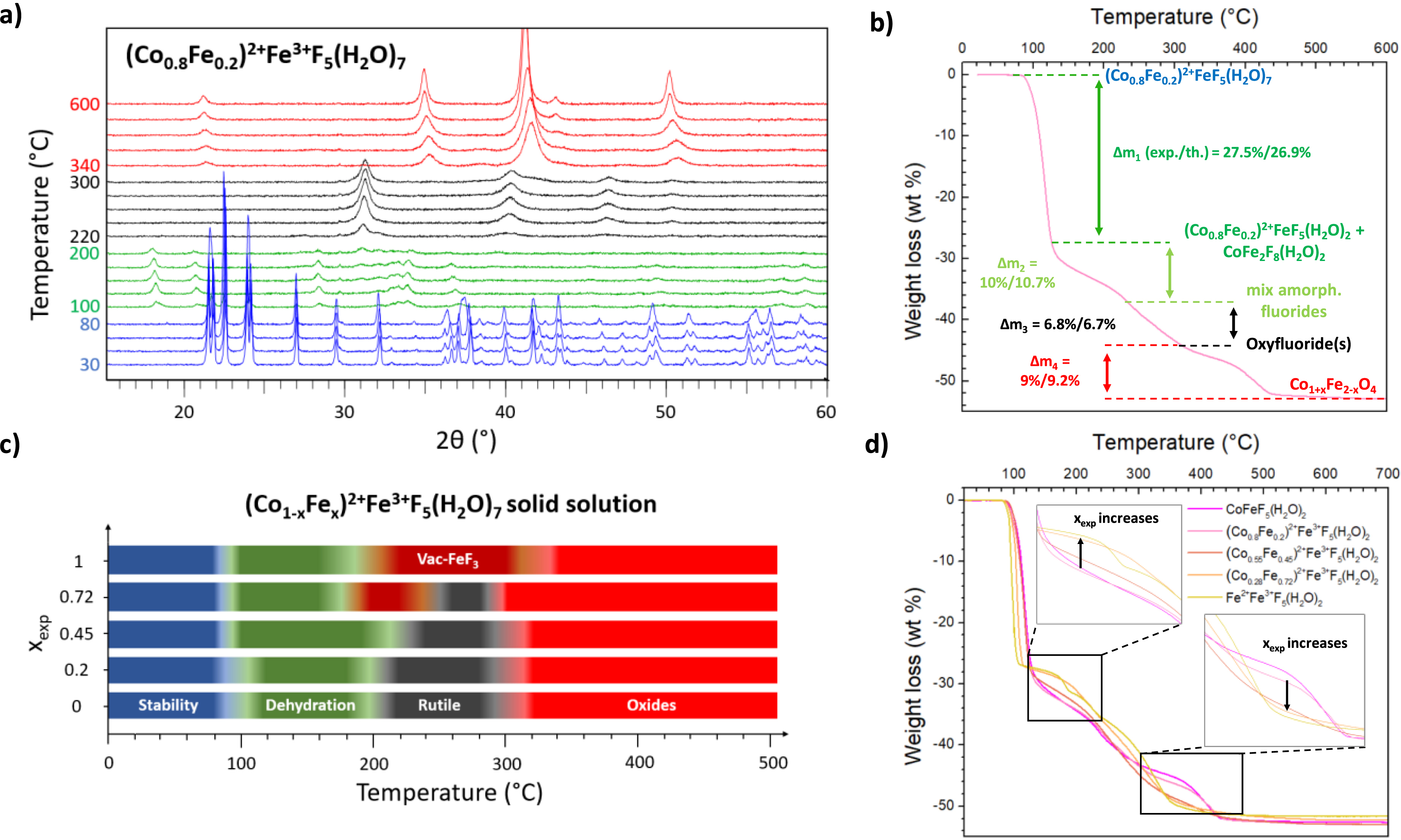
(a) Evolution of the X-ray diffractograms of (Co0.8Fe0.2)2+Fe3+F5(H2O)7 with temperature under ambient air. (b) TGA analyses of (Co0.8Fe0.2)2+Fe3+F5(H2O)7 performed under ambient air. (c) Temperature range of stability domains determined by HT-XRD for (Co1−xFex)2+Fe3+F5(H2O)7. (d) Corresponding TGA analyses performed under ambient air.
The HT-XRD results, summarized for all the compositions in Figure 2c, show that the temperature range for obtaining pure oxyfluoride(s) with rutile structure (in black) shrinks as the amount of Fe2+ increases, until it disappears completely for Fe2F5(H2O)7 (xexp = 1). This trend indicates that Co2+ is required to produce the rutile oxyfluorinated phase. In order to better understand the differences between the thermal behavior of the (Co1−xFex)2+FeF5(H2O)7 compounds, the PXRD diagrams at 120 °C where MFeF5(H2O)2 and MFe2F8(H2O)2 phases are produced from the thermal degradation of the initial precursors, have been studied. The data obtained from Rietveld refinements through two hypotheses (Figures S14–16 and Tables S10–12) showed that (Co1−xFex)2+Fe3+F5(H2O)7 is decomposed into (Co1−xFex)2+Fe3+F5(H2O)2 and Co2+Fe2F8(H2O)2, and additionally to Fe2F5(H2O)2 and Fe3F8(H2O)2 for xexp ⩾ 0.45. In fact, the linear increase in unit cell volume of the M2+FeF5(H2O)2-type phase as a function of xexp indicates the existence of a solid solution for (Co1−xFex)2+Fe3+F5(H2O)2 while the invariant volume for the M2+Fe2F8(H2O)2-type phase proves that the (Co1−xFex)2+Fe2F8(H2O)2 solid solution does not seem to exist (Figure S16). The formation of pure Fe phases, Fe2F5(H2O)2 and Fe3F8(H2O)2, manifested by the presence of α-Fe2O3 on PXRD up to 600 °C for xexp ⩾ 0.45 compositions, could be explained by the mass balance. Indeed, for all 0 ⩽ xexp ⩽ 0.72 compositions, a spinel-type phase indexed as CoFe2O4 is observed at 600 °C, with a ratio n(Fe)/n(Co) equal to 2. For xexp ⩾ 0.45 compositions, the ratio n(Fe)/n(Co) is superior to 2 and consequently, an iron-based oxide is required to achieve the mass balance, which is α-Fe2O3, as observed in Figure S13. On the other hand, for xexp ⩽ 0.2 compositions, only spinel-type CoFe2O4 is identified although n(Fe)/n(Co) < 2 so a Co-rich material is needed to equilibrate the mass balance. In our previous work on CoFeF5(H2O)7, the PXRD pattern at 600 °C was identified as a mixture of CoFe2O4 and CoO [29, 30], but as shown in Figure S17, it’s more likely to be a mixture of two spinel-type oxides with the formulations Co2+(Co0.24Fe1.76)3+O4 and Co2+(Co1.17Fe0.83)3+O4. These formulations were calculated according to their unit cell volumes determined by Le Bail refinements, 583.1 and 549.2 Å3, respectively, and used in the formula extracted from Vegard’s law for the solid solution Co2+(Co2−xFex)3+O4 (Figure S18). The formula Co2+(Co0.24Fe1.76)3+O4 and Co2+(Co1.17Fe0.83)3+O4 indicate a partial oxidation of Co2+ to Co3+, which has already been observed in the literature for the thermal treatment of CoF2 under similar thermal treatment conditions [33]. By plotting the respective spinel volume as a function of xexp obtained by Le Bail refinements for the different compositions (Figure S19), a gradual increase in unit cell volume is observed, indicating a progressive increase in the amount of Fe in the spinel up to a limit dictated by CoFe2O4. Finally, the reason for the appearance of CoFe2F8(H2O)2 and Fe3F8(H2O)2 phases is probably related to a partial oxidation of Fe2+ ions under such thermal decomposition conditions (high temperature, ambient air), leading to Fe3+-rich phases, which is not obviously observed for Fe2+-free Co2+Fe3+F5(H2O)7 (Figure S11).
The comparison of the TGA profiles in Figure 2d shows an evolution of the thermal behavior according to the proportion of Fe2+ in the initial precursor. First, the thermal behaviors of xexp = 0 and 0.2 are very similar, which is not surprising since, from the previous results at 120 °C, x = 0.2 is mainly composed of M2+FeF5(H2O)2. The few changes can be attributed to the contribution of the thermal behavior of CoFe2F8(H2O)2, which is quite similar to that of CoFeF5(H2O)2, since it decomposes into a rutile oxyfluoride and then a spinel-type oxide (Figure S20). For the composition xexp = 0.45 there is a significant change between 300–450 °C which could be attributed to the appearance of pure Fe phases to the detriment of (Co1−xFex)2+Fe3+F5(H2O)2. For xexp = 0.72, the thermal behavior is very close to that of pure Fe2F5(H2O)7, except that a clear distinction between the two successive weight losses associated with the formation of FeF2.5O0.25□0.25 and FeF2.66O0.17□0.17 cannot be made (Figure S10).
2.3. Synthesis and characterization of the oxyfluoride(s)
The oxyfluorides with the theoretical formulation (Co(1−x)/2)2+(Fe(1+x)/2)3+O(1+x)/2F(3−x)/2 assuming the formation of rutile MX2, were prepared by thermal treatment of the corresponding hydrated fluorides (Co1−xFex)2+Fe3+F5(H2O)7. For each composition, the selected calcination conditions to obtain the pure rutile oxyfluorides, according to XRD and theoretical weight loss (about 44–45 wt% for all compositions) are summarized in Table S13. More details on the determination of the thermal treatment conditions are given for xexp = 0 in our previous study [30].
After calcination, all oxyfluorinated phases were indexed in the tetragonal P42/mnm space group (Figure 3a). The PXRD patterns were refined by the Le Bail refinement method (Figures S21–24), as exemplified for the calcined (Co0.8Fe0.2)2+ Fe3+F5(H2O)7 precursor in Figure 3b. According to the evolution of the volume obtained for the different rutile oxyfluorides (Figure S25), it seems that from x ⩾ 0.45, Fe3+ and O-enriched oxyfluorides are formed, since the volume of the unit cell decreases slightly, in agreement with the radii of Co2+, Fe3+, O2− and F− (0.742 Å, 0.649 Å, 1.366 Å and 1.300 Å, respectively) [31]. However, the volume of xexp = 0.2 is equivalent to xexp = 0, indicating a similar chemical composition, even though the substitution was previously demonstrated in the (Co0.8Fe0.2)2+Fe3+F5(H2O)2 precursor. This clearly shows the complexity of the decomposition mechanism, especially for (Co1−xFex)2+Fe3+F5(H2O)2 and Co2+Fe2F8(H2O)2 hydrates, which seem to give a similar oxyfluoride for xexp ⩽ 0.2, while the metal ratio is different. For the sample xexp = 0.72, an impurity of α-Fe2O3 is present, which is not surprising given the narrow stability window of the oxyfluoride (Figure 2c). Rietveld refinement of the PXRD pattern shows an α-Fe2O3 mass fraction close to 60 wt%, but this could be misestimated given the complexity of the refinement (Figure S26).
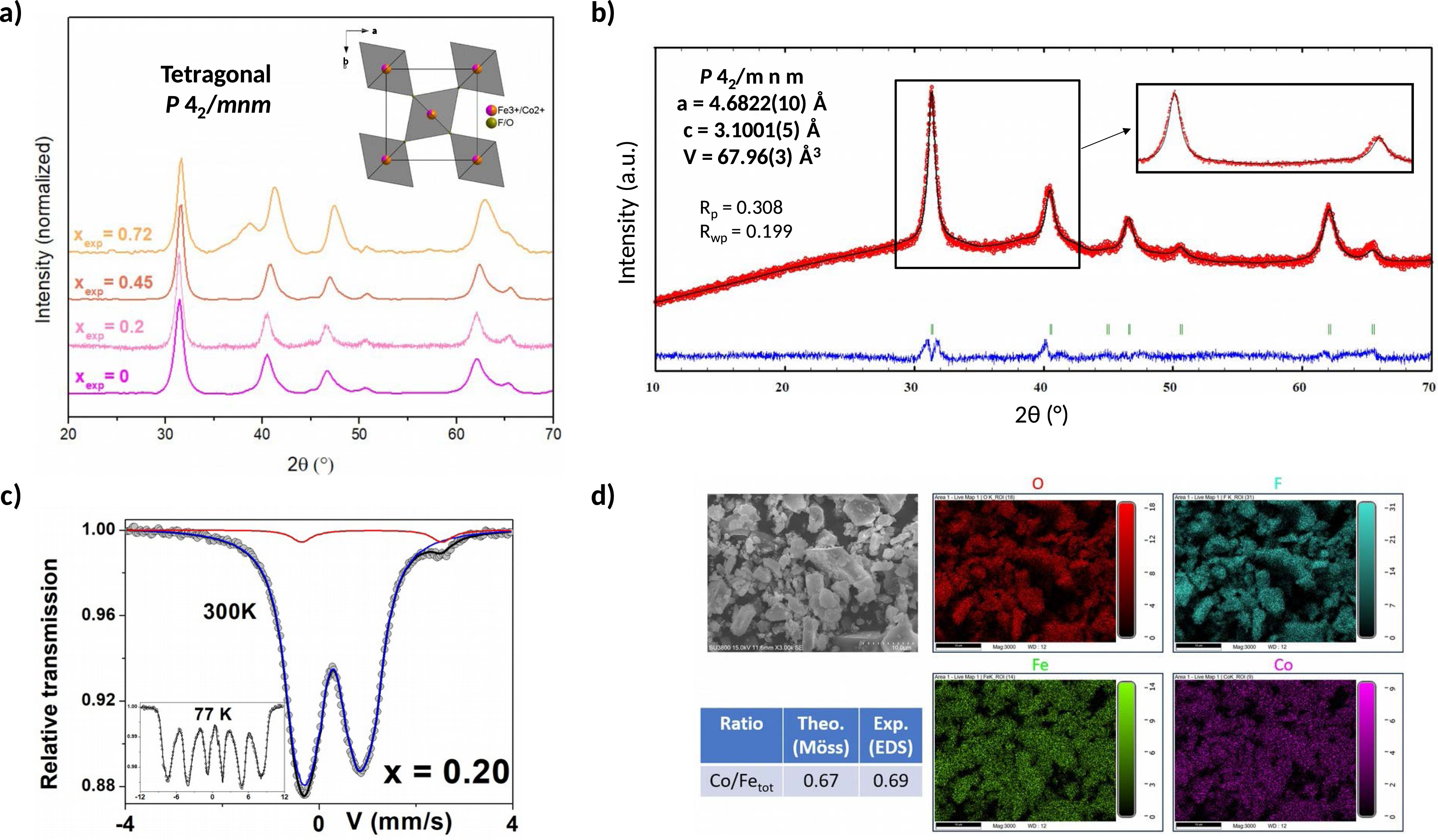
(a) Calcined (Co1−xFex)2+Fe3+F5(H2O)7 PXRD diagrams with the corresponding [001] projection of the rutile structure for oxyfluorides, (b) Le Bail refinement of calcined (Co0.8Fe0.2)2+Fe3+F5(H2O)7, (c) 57Fe Mössbauer spectra at 300 K and 77 K of calcined (Co0.8Fe0.2)2+Fe3+F5(H2O)7, (d) SEM images of the calcined (Co0.8Fe0.2)2+Fe3+F5(H2O)7 and elemental mapping of each metal.
The Mössbauer spectra obtained at 300 K and 77 K are shown in Figure S27 and exemplified for calcined xexp = 0.2 in Figure 3c. At 300 K, a significant change from a pure quadrupolar hyperfine structure (xexp ⩽ 0.45) to a mixed quadrupolar and magnetic structure (xexp = 0.72) is observed, while the Mössbauer spectra at 77 K consist only of a pure magnetic structure for all compositions. From the XRD analysis, this magnetic structure at 300 K is probably related to the presence of α-Fe2O3 magnetic impurity. In addition, as shown in Figure S27 (xexp = 0.20 and 0.45), two quadrupolar components can be distinguished, which can be clearly attributed to a large contribution of Fe3+ species on the one hand, and to a very small contribution of Fe2+ species on the other hand, which cannot be easily detected from the magnetic hyperfine structures due to their complexity. The quadrupolar spectra were described by similar models as described above, while the magnetic spectra were described using a discrete distribution of the hyperfine field linearly correlated with that of the isomer shift to account for the asymmetry of the sextets. The mean refined values are listed in the Table of Figure S27. These results clearly show that calcination leads, on the one hand, to the almost complete disappearance of Fe2+ ions and, on the other hand, to the appearance of magnetic oxyfluorinated phases containing predominantly Fe3+ species. It is important to note that the large decrease in Fe2+ content is not related to the difficulty of stabilizing Fe2+ in the rutile-structure oxyfluoride as Brink et al. demonstrated that it is possible to solubilize up to 30% of FeF2 in rutile FeOF [34]. This decrease is more likely related to Fe2+ oxidation during thermal decomposition, as has been observed after thermal treatment of the mixed-valent iron fluoride hydrates Fe2F5(H2O)2 and Fe3F8(H2O)2 [32]. However, the complexity and lack of resolution of the magnetic hyperfine structures at 77 K make it difficult to rule out the presence of α-Fe2O3 and to estimate its precise content. The comparison of the quadrupolar hyperfine structures at 300 K of the spectra xexp = 0 and 0.2 shows three components for Fe3+ species that are significantly different (Figure S28). This result shows that the cationic distribution is modified by increasing the amount of Fe. However, the mean values of the isomer shift are unchanged, suggesting that the mean anionic environment remains similar, which can be roughly estimated to be about 50:50 F:O. Furthermore, the 77 K spectra show a pure magnetic structure with broadened lines: the mean isomer shift values are also similar, while the distributions of the hyperfine fields are consistent with different atomic environments of the Fe3+ species, as inferred from the 300 K spectra.
EDX-SEM analysis revealed the presence and homogeneous distribution of F, O, Co, and Fe within the calcined materials (Figures S29–32) as shown in Figure 3d. The Co/Fetot ratio after calcination is still in agreement with the respective precursor composition determined by Mössbauer spectrometry and EDX-SEM. Although a dominant impurity of α-Fe2O3 is observed by PXRD for the sample xexp = 0.72, we are not able to distinguish two clearly separated phases by elemental mapping (Figure S32). This could indicate an intimate mixture of both phases, divided into nanodomains visible only by High Resolution Transmission Electronic Microscopy (HR-TEM), as already observed in our previous study [30]. This is supported by the broadening of the Bragg diffraction peaks observed after thermal treatment (Figure 3a), compared to those of the precursor, indicating small coherent diffraction domains estimated in the range of 10 nm by the Laue–Scherrer relation. High specific surface areas around 60–80 m2⋅g−1 (Table S13) were obtained with such calcination conditions, as indicated by the grain size reduction before and after calcination (Figure S33).
The molar ratio n(Co)/n(Fe) in the calcined samples has been verified by ICP-OES (Table S14) and agrees with the formulation previously determined for the initial hydrated precursors. However, for compositions with a higher amount of Fe2+ (e.g., x = 0.45 and 0.72), a slight difference between experimental and theoretical is observed. This difference could be explained by an incomplete dissolution of the material, since the experimental n(Co)/n(Fe) ratio is still in agreement with the theoretical one, or by the presence of amorphous impurities resulting from thermal decomposition of additional Fe2F5(H2O)2 and Fe3F8(H2O)2.
From this analysis, we can first conclude that the structure as well as the chemical composition of the oxyfluoride derived from (Co0.8Fe0.2)2+Fe3+F5(H2O)7 is similar to that of the oxyfluoride derived from Co2+Fe3+F5(H2O)7, which is surprising given the difference in the metal ratios and the intermediates involved. Thus, the excess Fe3+ may be in the form of an amorphous phase not visible by PXRD, or in another Fe enriched oxyfluoride with indistinguishable unit cell parameters arising from CoFe2F8(H2O)2. Oxyfluorides prepared from (Co0.55Fe0.45)2+Fe3+F5(H2O)7 and (Co0.28Fe0.72)2+Fe3+F5(H2O)7 are found to be enriched in iron, but not as much as in the initial precursor value, as suggested by the high amount of α-Fe2O3 impurity observed for calcined xexp = 0.72.
2.4. Electrochemical performance for oxygen evolution reaction (OER)
Cyclic voltammetry (CV) in 1M KOH electrolyte was performed to evaluate the performance of the calcined (Co1−xFex)2+Fe3+F5(H2O)7 samples as electrocatalysts for OER (Figure 4a). For all compositions, the Co2+/3+ oxidation peak is clearly visible and varies from 1.16 to 1.18 V vs. RHE depending on Fe2+ amount. This shift could be explained by a slight modification of the Co2+ environment in the rutile phase, which is gradually enriched in Fe, and consequently in O2− for xexp = 0.45 and 0.72 samples. Both position and intensity of the Co2+/3+ oxidation peak are identical between the composition xexp = 0 and 0.2, the only difference being a slight broadening of the oxidation peak. This could be due to the contribution of a second oxyfluoride originating from CoFe2F8(H2O)2 which, according to the work of Lemoine et al., shows a maximum intensity of Co2+/3+ oxidation at a slightly higher potential of about 1.20 V vs. RHE [27] instead of 1.16 V vs. RHE for Co0.5Fe0.5O0.5F1.5 (xexp = 0) [30]. For xexp = 0.45 and 0.72, the intensity of the oxidation peak decreases gradually and proportionally to the amount of Co2+, indicating a reduced activity for the main Co2+ active site. In terms of overpotential (Figure 4b), Tafel slope (Figure 4c), mass activity (Figure 4d), and specific activity (Figure 4e), the calcined xexp = 0 and 0.2 samples show similar performance, which are the best of the calcined (Co1−xFex)2+FeF5(H2O)7 series, namely for xexp = 0.2 an overpotential of 320 mV at 10 mA⋅cm−2, a low Tafel slope of 33 mV⋅dec−1, a mass activity of 112 A⋅g−1, and a specific activity of 1.67 A⋅m−2. This similar activity between calcined xexp = 0 and 0.2 confirms that both structures and chemical compositions are relatively close, and it does not affect the global OER performance regardless of the presence of an additional phase. On the other hand, the OER activity decreases progressively for calcined xexp = 0.45 and 0.72, which could be attributed to the increase of less active Fe-enriched oxyfluorinated phases to the detriment of more active Co-phases. Chronopotentiometric measurements were carried out at a current density of 125 mA⋅cm−2 on calcined xexp = 0 and 0.2 to study the effect of Fe increase on the stability (Figure S34). Both samples are similar and reasonably stable, with only an increase of about 150 mV after 17 days at 125 mA⋅cm−2.
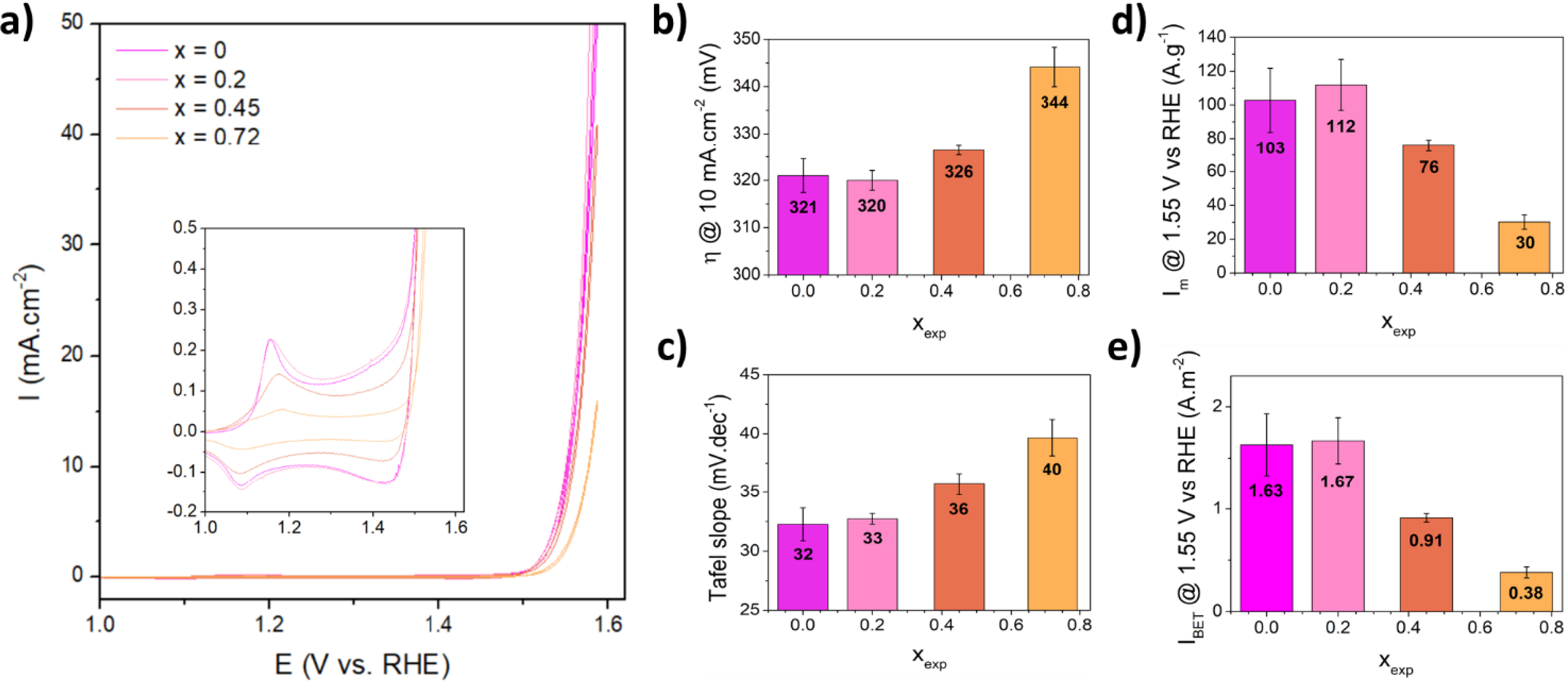
(a) Cyclic voltammetry curves of calcined (Co1−xFex)2+Fe3+F5(H2O)7 in 1M KOH, the inset representing a zoom on the redox peaks area. (b) Overpotential at 10 mA⋅cm−2 for the different compositions. (c) Tafel slope. (d) Mass activity at 1.55 V vs. RHE. (e) Specific activity at 1.55 V vs. RHE.
3. Conclusion
In this work, the (Co1−xFex)2+Fe3+F5(H2O)7 solid solution with 0 ⩽ xexp ⩽ 0.72 is synthesized by a simple coprecipitation inspired by our previous work, as precursors of Co/Fe oxyfluorides as OER catalysts. XRD, EDX-SEM and Mössbauer spectrometry analyses confirmed the Co2+/Fe2+ substitution in the heptahydrated precursors, but the quantification of the Fe2+ amount indicates that it is incomplete, due to a small part of Fe2+ oxidized to Fe3+ during the synthesis. A detailed study of the thermal behavior of these hydrates by coupling HT-XRD and TGA analyses revealed for the first time a complex decomposition into a mixture of (Co1−xFex)2+FeF5(H2O)2 and CoFe2F8(H2O)2 dihydrates for xexp = 0 and 0.2, and additionally into Fe2F5(H2O)2 and Fe3F8(H2O)2 for xexp = 0.45 and 0.72. Then, depending on the chemical composition of MFeF5(H2O)2 and MFe2F8(H2O)2 (M = Co2+ and/or Fe2+), these materials are decomposed into various mixed Fe/Co or pure amorphous Fe oxyfluorides. These oxyfluorinated materials, prepared by appropriate thermal treatment in a muffle furnace, were tested for OER in alkaline medium. The results show that it is possible to replace 20% of the cobalt by iron without affecting the electrochemical performance. For higher substitution rates (xexp ⩾ 0.45), the proportion of Fe2F5(H2O)2 and Fe3F8(H2O)2, giving after thermal decomposition Fe-pure oxyfluorides, is increasing at the detriment of CoFeF5(H2O)2 and CoFe2F8(H2O)2 leading to Co-containing oxyfluorides with higher performance. These results seem to indicate that the best electrochemical performance is obtained for a Co:Fe ratio of 1:1. In order to avoid the formation of pure Fe phases, the synthesis of Co(1−x)/2Fe(1+x)/2O(1+x)/2F(3−x)/2 oxyfluorides from the alternative hydrate solid solution Co1−xFexF2(H2O)4, which does not induce the formation of phases mixing during the thermal decomposition, is in progress. In addition, EXAFS and PDF studies will be performed to understand the local environment of transition metals in these oxyfluorides.
4. Experimental section
4.1. Synthesis of fluorinated materials
Chemicals
The heptahydrate fluorides were synthesized using Fe(NO3)3•9H2O (⩾98%, Alfa Aesar), CoCl2•6H2O (99.5%, Acros Organics), and FeCl2•4H2O (98% Alpha Aesar). Hydrofluoric acid solution (HF 48 wt%, Honeywell), methanol (MeOH, 99.8% Honeywell), and absolute ethanol (99.8%, Carlo Erba Reagents) were used as received. Warning! HF is a hazardous chemical, toxic by inhalation, contact with skin, and if swallowed. All necessary precautions were taken during our experiments.
4.1.1. Synthesis of (Co1−xFex)2+Fe3+F5(H2O)7 (0 ⩽ xtheo ⩽ 0.75)
(Co1−xFex)2+Fe3+F5(H2O)7 (0 ⩽ xtheo ⩽ 0.75) precursors were synthesized by coprecipitation at room temperature. Fe(NO3)3•9H2O and CoCl2•6H2O are dissolved in 10 mL HF solution (HF48 wt%) under stirring while FeCl2•4H2O is separately dissolved in 1 mL of MeOH. Ongoing study aims to replace HF by solid sources as NH4F or KF for sustainability and security issues. This separate dissolution is necessary because Fe2+ is easily oxidized to Fe3+ in HF or EtOH solutions. After complete dissolution, 15 mL of EtOH is added to the FeCl2•4H2O solution and quickly poured into the HF solution containing Fe3+ and Co2+ species, leading to the precipitation of (Co1−xFex)2+Fe3+F5(H2O)7. Stirring is maintained for 5 min to ensure a complete reaction. The precipitate is filtered, washed several times with EtOH, and dried under ambient conditions. Polycrystalline powders ranging in color from pink to yellow are obtained with good yields and high purity.
4.1.2. Synthesis of Co(1−x)/2Fe(1+x)/2O(1+x)/2F(3−x)/2 (0 ⩽ xexp ⩽ 0.72)
Co(1−x)/2Fe(1+x)/2O(1+x)/2F(3−x)/2 (0 ⩽ xexp ⩽ 0.72) samples were synthesized by calcination under air of 200 mg of the corresponding hydrated fluoride (Co1−xFex)2+Fe3+F5(H2O)7 at various temperatures for a short period of time in a muffle furnace (Nabertherm LT 3/12). The temperature profile is represented in Figure S35 and the calcination conditions in Table S13. The sample was directly placed in the muffle furnace when the targeted temperature was reached and heated for a suitable time. The sample was finally removed and cooled to ambient temperature under ambient air.
4.2. Characterization
X-ray diffraction (XRD)
X-ray diffraction patterns were collected in the range of 10° ⩽ 2𝜃 ⩽ 120° on a PANalytical MPD-PRO diffractometer with a Bragg-Brentano geometry, equipped with a Co Kα source (kα1 = 1.78901 Å; kα2 = 1.79290 Å) and a linear X’Celerator detector. Rietveld refinements were performed by using the Fullprof program.
High-Temperature X-ray diffraction (HT-XRD)
High-Temperature X-ray diffraction (HT-XRD) was performed under ambient air in an Anton Paar XRK 900 high temperature furnace with the diffractometer described above. The samples were heated from 30 to 600 °C at a heating rate of 3 °C⋅min−1. X-ray diffraction patterns were recorded in the [8–80°] 2𝜃 range with a scan time of 15 min at 20 °C intervals from room temperature to 400 °C and at 50 °C intervals from 400 to 600 °C.
Thermogravimetric analyses (TGA)
Thermogravimetric analyses were carried out using a thermoanalyzer SETARAM TGA 92 under ambient air flow at 100mL/min with a heating rate of 2 °C⋅min−1 from room temperature up to 600 °C.
Scanning Electron Microscopy (SEM)
Scanning Electron Microscopy images were obtained thanks to a Hitachi microscope (Hitachi SU3800). The acceleration voltage used is 15 kV. Elemental quantitative microanalyses were performed using an EDAX Energy Dispersive X-ray Octane Elect Super EDS detector.
N2 sorption
The specific surface areas were measured at 77 K using a TriStar II 3020 (Micrometrics). The samples were degassed under secondary vacuum at 80 °C for 12 h prior to measurement. The specific surface areas were calculated using the Brunauer–Emmett–Teller (BET) method.
57Fe Mössbauer spectrometry
Mössbauer measurements were obtained in transmission geometry with a 925 MBq 𝛾-source of 57Co/Rh on a conventional constant acceleration drive. The amount of substance for each sample weighed was calculated to contain 5 mg of Fe per cm2. Spectra were fitted using the MOSFIT program [35] involving quadrupolar and/or magnetic components with Lorentzian lines; the isomer shift values are referred to that of α-Fe at room temperature. The velocity of the source was calibrated using a α-Fe foil as a standard at room temperature.
Elemental analysis
From an initial solution containing iron and cobalt (1000 ppm), standard solutions have been prepared to obtain the concentrations: 0, 0.5, 1, 2, 5, and 10 ppm. The intensity of the signal as a function of the element concentration, obtained for each element (Fe, Co) is reported in (Figure S36). The samples were prepared by digestion of approximately 10 mg of samples dissolved first in 5 wt% HNO3(aq) followed by a dilution with deionized water by a factor of 100 to be in the right range of measurements.
Electrochemical measurements
A Biologic SP200 potentiostat and EC-lab software were used. Ag/AgCl reference (4M KCl gel) and carbon rod counter electrodes were employed for the measurements. Custom-built one-compartment glass electrochemical cells were employed, and 1M KOH was used as the electrolyte. Working electrodes were constructed from Toray carbon paper. A catalyst ink was prepared by sonicating typically 10 mg of the catalyst and 0.1 mg of carbon nanotubes in 1 mL of 2:1 ethanol:water (V:V) with 80 μL of Nafion. The ink was dropped-cast onto the working electrodes and allowed to dry under ambient conditions for 20 min prior to use. Catalyst loadings on the carbon paper were 0.1 mg⋅cm−2 and 1 mg⋅cm−2 for cyclic voltammetry and chronopotentiometry, respectively. Prior to electrochemical measurements, the impedance between reference and working electrode was recorded in open circuit, and the ohmic drop was subsequently corrected for at 95% with the ZIR function in the EC-lab software.
Declaration of interests
The authors do not work for, advise, own shares in, or receive funds from any organization that could benefit from this article, and have declared no affiliations other than their research organizations.
Acknowledgments
The authors attached to IMMM gratefully acknowledge the technical platforms “X-ray Diffusion and Diffraction” and “Electron Microscopy” of IMMM (Le Mans University) as well as the French National Research Agency (ANR OPIFCAT, ANR-20-CE08-0026) and the Fondation Banque Populaire d’Entreprise de l’Ouest for financial support. NK acknowledges NSERC for its Discovery Grant RGPIN-2019-05927, and the International Emerging Action IEA. All authors thank FRQNT Samuel de Champlain program, award 293526.