1 Introduction
FeII–III hydroxysalt green rusts (GR) were long ago recognised as transitory intermediate products during the wet corrosion of iron-base materials. For instance, Girard, entitling his thesis work in 1935 “de la constitution des rouilles ” [10], attributed a green compound forming in a sulphated medium to a hydrated magnetite. Thus, the preparation of GRs by oxidation of Fe(OH)2 was the predilection of corrosion scientists that essentially tried to simulate the process of oxidation of Fe species. It was used extensively for many years in several aqueous solutions containing the major anions Cl−, , , but also F−, I−, Br−, , , , [2,5,6,14–18,24,25]. In contrast, , or OH−, never gave successful results. During aerial exposure of the solution, the electrode potential and pH of the aqueous solution are recorded and the precipitates are filtered and analysed by XRD and Mössbauer spectroscopy. In particular, any salient point in the curves is carefully analysed since it is assumed to correspond to particular conditions in the reaction process. This method for preparing GRs became very reliable but is obviously cumbersome and not so efficient in comparison with the coprecipitation method [3,22,23]. However, the and pH curves gave very valuable thermodynamic information that allowed us to draw the –pH Pourbaix diagrams. These experiments were completed by determining the end products of oxidation, which were very various and were essential for understanding the properties of corroded materials. A comparison with a fast oxidation of GR as done with H2O2 or a slow oxidation after drying or by voltammetry or by bacterial reduction of ferric oxyhydroxides is also made in this article for clarity. It is the clue of the formation of partially deprotonated FeII–III hydroxycarbonate fougerite in anoxic gleysols that could be written in its general form , where x lies in the interval.
2 Aerial oxidation of Fe(OH)2 within solution
2.1 Experimental and pH versus time curves
Ferrous hydroxide precipitated into solution by mixing a ferrous salt comprising anion with caustic soda. In most studies, initial conditions were given by a ratio of the concentration of ferrous salt over that of NaOH most often comprised between 0.2 and 0.4 mol l−1. It is equivalent to as named in the coprecipitation method where R was defined as {[OH−1]/[Fetotal]} [3,22,23]. Then, the solution was stirred in the presence of air at constant velocity in a beaker with a magnetic rod and two electrodes recorded pH and potential using a calomel electrode as a reference, even though the potential was reported with respect to the standard hydrogen electrode (SHE). Ferrous chloride FeCl2⋅4 H2O and melanterite FeSO4⋅7 H2O were appropriate for Cl− and , but it became much less easier for anions, since carbonate salts were not soluble; Fe(OH)2 precipitated with ferrous sulphate before adding sodium carbonate to obtain GR1() [5]. The same was done for GR1() [24], GR2() [17], and GR2() [18]. In presence of an excess of ferrous salt to precipitate Fe(OH)2, typical curves of and pH vs. time curves display three stages (Fig. 1). A first one (A) ends at the inflection point where all ferrous hydroxide is transformed into GR incorporating present anions . During a second stage B ending at inflection point , the GR oxidises into the usual ferric rusts and disappears completely. A third stage C from to corresponds to the oxidation of FeII ions left within the solution. Fig. 1 reports specifically the case of the sulphate medium, which is chosen here since it was the most widely studied system, setting the initial concentrations at to obtain solely GR2() [6]. Samples of transient compounds during oxidation were analysed by Mössbauer spectroscopy at 15 K (Fig. 2) where they were set in a holder inside the cryostat only a few seconds after filtration.
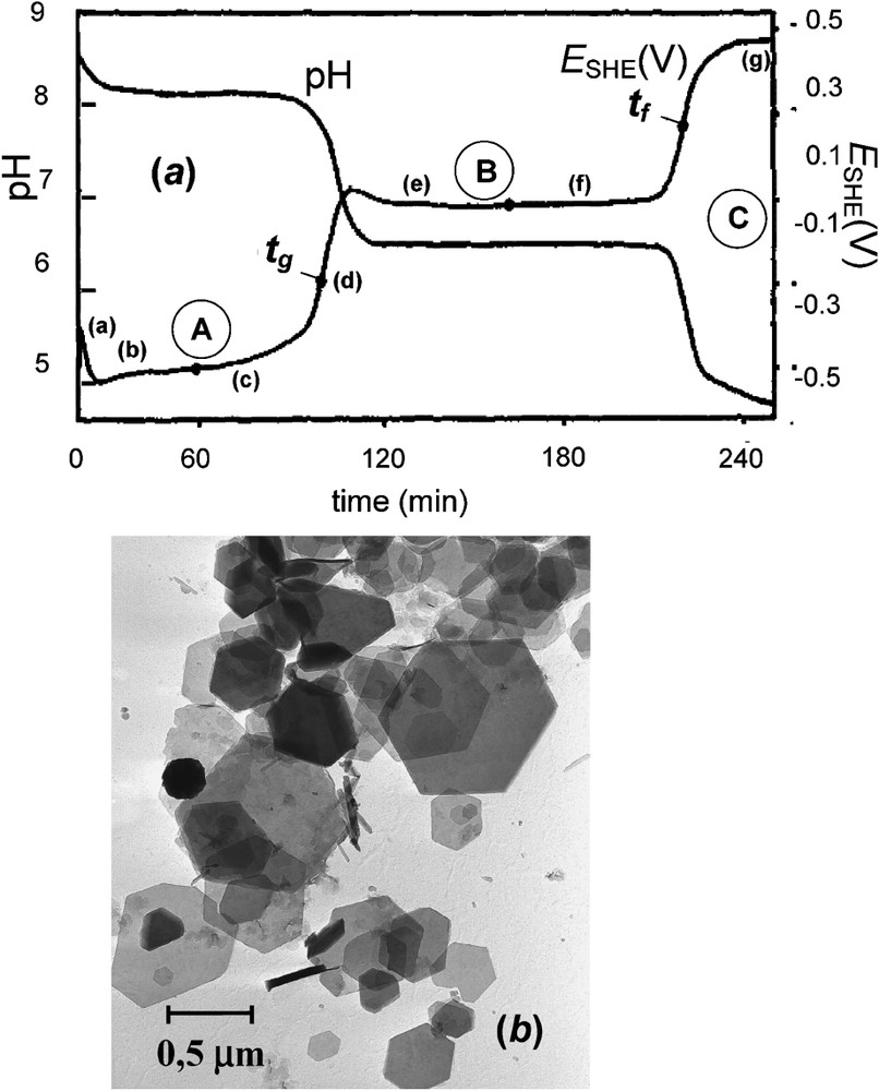
(a) Zero-current potential (SHE) and pH vs. time curves recorded during the oxidation of an aerated suspension of ferrous hydroxide in a sulphate containing medium for initial ratio . Three stages A, B and C illustrated by plateaus when and pH stay constant correspond to three equilibrium reactions. At , 100% of GR2() forms and at there exist only one solid phase, lepidocrocite γ-FeOOH with FeII ions within solution. Points (a)–(g) indicate the times at which the precipitates analysed by Mössbauer spectroscopy were sampled [6]. (b) Transmission electron micrograph of sample of GR at [6].
(a) Courbes du potentiel d'électrode à courant nul (SHE) et pH, enregistrées en fonction du temps au cours de l'oxydation à l'air d'une suspension d'hydroxyde ferreux dans un milieu contenant du sulfate pour un rapport initial . Trois étapes A, B et C, illustrées par des plateaux où et pH restent constants, correspondent à trois réactions à l'équilibre. À , 100% de rouille verte se forme et à existe une seule phase solide, la lépidocrocite γ-FeOOH, en compagnie d'ions FeII en solution. Les points (a)–(g) indiquent les moments où ont été prélevés les échantillons en vue de l'analyse par spectrométrie Mössbauer [6]. (b) Micrographie électronique en transmission d'échantillon de rouille verte prélevé à [6].
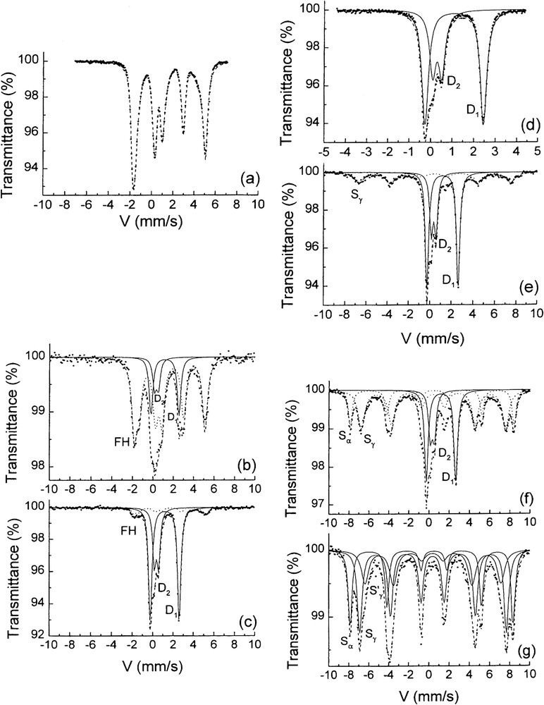
Transmission Mössbauer spectra measured at 15 K of the solid phases sampled at various times of the oxidation of ferrous hydroxide. Times (a)–(g) of sampling are indicated on the vs. time curve of Fig. 1 [6]. (a) Ferrous hydroxide prepared in basic medium, (b) and (c) in plateau A during the first stage: a mixture of ferrous hydroxide and GR, (d) at , GR is alone, (e) and (f) during the second stage in plateau B, γ-FeOOH and then α-FeOOH increase at the expense of GR, (g) during the last plateau C, there are only α- and γ-FeOOH as solid phases.
Spectres Mössbauer par transmission mesurés à 15 K des phases solides prélevées à diverses périodes de l'oxydation de l'hydroxyde ferreux [6]. Les instants de prélèvement de (a) à (g) sont indiqués sur la courbe en fonction du temps de la Fig. 1. (a) Hydroxyde ferreux préparé en milieu basique, (b) et (c) mélange d'hydroxyde ferreux et de rouille verte sur le plateau A au cours de la première étape, (d) la rouille verte est seule à , (e) and (f) au cours de la seconde étape sur le plateau B, γ-FeOOH, puis α-FeOOH croissent au dépens de la rouille verte, (g) au cours du dernier plateau C ne se trouvent que les phases solides α- and γ-FeOOH.
2.2 Mass-balance diagram
2.2.1 Formation of green rust ()
Interpretation of the and pH versus time curves is easy within the frame of the mass-balance diagram where R={[OH−]/[Fetotal]} is plotted versus x={[FeIII]/[Fetotal]} (Fig. 3) [22,23]. Initial conditions are shown in the diagram by a point on the co-ordinate axis that corresponds to a mixture of the initial precipitate of Fe(OH)2 at point G, , and FeII within solution at F, . During the overall oxidation process, Fe(OH)2 transforms into FeOOH and reaction paths follow straight lines with a slope of 1 (Fig. 3). Therefore, the straight line that goes directly through the point representing GR2( at has for co-ordinate at origin ; is the initial value of R to obtain 100% of GR with an excess of FeII with respect to Fe(OH)2 at . Stage A that starts at point A () to end at B () is thus the oxidation of Fe(OH)2 (cf. Fig. 2a) into GR2() (cf. Fig. 2d) using this initial excess of FeII and anions at :
| (1a) |

Mass-balance diagram of iron species in a sulphate containing medium where GR2() forms. Three routes are drawn to illustrate the aerial oxidation of Fe(OH)2 where initial values of R are , and .
Diagramme bilan matière des espèces du fer dans un milieu contenant des ions sulfate où se forme GR2(). Trois cheminements sont représentés pour illustrer l'oxydation à l'air de Fe(OH)2 où les valeurs initiales de R sont , et .
Then, stage B that elapses from point B () to C () is the oxidation of GR2() into FeOOH, here lepidocrocite, that releases Fe2+ ions and anions into solution:
| (1b) |
Then, during stage C, Fe2+ within solution gets oxidised into FeOOH (cf. Fig. 2g) for one third of it and 2/3 in solution; the solution gets acidic gradually (cf. Fig. 1a):
| (1c) |
As a whole, the initial Fe(OH)2 at point A becomes ferric oxyhydroxide α-FeOOH goethite and Fe3+ ions in acidic solution at point D according to:
| (1d) |
At D on tie-line EI, the mixture of FeOOH and Fe3+ is in the 8:1 proportion (Eq. (1d)).
2.2.2 Formation of magnetite ()
The direct oxidation of Fe(OH)2 at stoichiometry, i.e. initially at , that starts at (point G) corresponds to the 2 reactions D and E where the and pH vs. time curves present only one inflection (point H) (Fig. 3). Fe(OH)2 becomes directly magnetite Fe3O4 and then magnetite gradually transforms in situ into γ-Fe2O3 maghemite (point E) rather than into FeOOH, since maghemite has the same spinel structure. Reactions are respectively:
| (2a) |
| (2b) |
2.2.3 Trigger value
It has been carefully established by coprecipitation of FeII and FeIII ions in the presence of that the formation of GR2() necessitates an excess of OH− ions [22,23]. This surprising result at a first glance comes from the mechanism of formation of the GR where Fe(OH)2 layers grow parallel to the surface of the solid ferric oxyhydroxide by trapping anions in between and electron transfer takes place from FeII to the ferric substrate [23]. The GR2() particle grows progressively and will separate from the shrinking FeOOH crystal sooner or later. Line thus plays a specific role and its intersect with separates two different behaviours corresponding to a value (Fig. 3). When , the straight line cuts tie-line GB joining Fe(OH)2 and GR2( before that joining GR2() and Fe3O4, i.e. BH. This mixture evolves into FeOOH and some magnetite may remain. If , all Fe(OH)2 transforms into GR2() and no magnetite is observed.
2.3 Products of oxidation within solution
2.3.1 Lepidocrocite and goethite for GR1(Cl−) and GR2() in acidic medium
The determination of the products of oxidation of GRs are of major importance for some technological issues involving corrosion and environmental science as well. It is also a topic by itself for explaining the genesis of minerals. Early works were devoted to the final products of oxidation of Fe(OH)2 when varying the initial ratio R={[OH−]/[Fetotal]}. This is illustrated for the chloride-containing medium where [16]. Mössbauer spectroscopy was used for analysing the final products (Fig. 4). Magnetite is obtained for , i.e. , then goethite α-FeOOH is maximum for . Then lepidocrocite γ-FeOOH is overwhelming around , whereas akaganeite β-FeOOH begins to appear for and is alone for . A comparable result is observed for the sulphate containing medium, i.e. magnetite for , then an increase of goethite that drops suddenly at where lepidocrocite appears at 75% and decreases slowly along with a new increase of goethite. In both examples, lepidocrocite appears at the end of stage B before it transforms into α-FeOOH according to reaction (1c) in acidic conditions if GRs form as its precursor in the pathway.

End-products of the aerial oxidation of Fe(OH)2 in chloride containing medium with respect to the initial ratio [13,14]. ▾ M: Magnetite, ▴ G: goethite, ■ L: lepidocrocite, ● A: akaganeite.
Produits finals de l'oxydation à l'air de Fe(OH)2 en milieu chloruré en fonction du rapport initial [13,14]. ▾ M : Magnétite, ▴ G : gœthite, ■ L : lépidocrocite, ● A : akaganéite.
2.3.2 Ferrihydrite and goethite for GR1() in basic medium
The carbonate-containing medium behaves differently at ; GR1() transforms into ferrihydrite, which itself transforms into goethite later on (Fig. 5) [1]. It was demonstrated that the evolution could be stopped by the adsorption of anions such as phosphate onto ferrihydrite. Field observations that ferrihydrite of reddish brown colour forms in waterlogged soils where bluish green fougerite lies are a good indication that the hydroxycarbonate is indeed concerned.
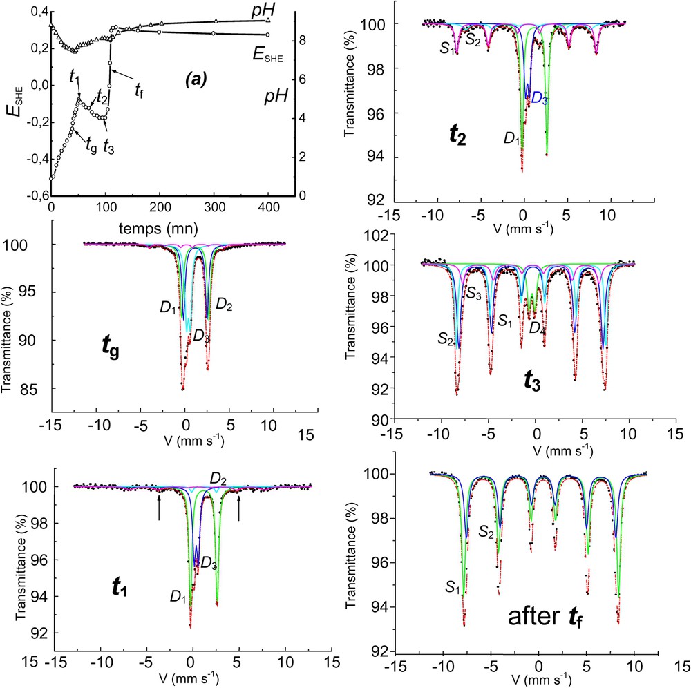
Aerial oxidation of Fe(OH)2 in the carbonate-containing solution and corresponding Mössbauer spectra showing the formation of ferrihydrite at the end of stage B before transforming into goethite. The solution is buffered by ions around pH 9. : doublets, : ferrihydrite sextet, : goethite sextets, : ferrihydrite doublet, : some alone, : some ferrihydrite, : goethite + ferrihydrite, : goethite + ferrihydrite. After : goethite alone.
Oxydation à l'air de Fe(OH)2 en solution carbonatée et spectres Mössbauer afférents montrant la formation de ferrihydrite en fin d'étape B, avant transformation en goethite. La solution est tamponnée par les ions aux alentours de pH 9.
Fig. 6 allows comparing the reaction path in the case of the carbonated medium with those of chloride and sulphate media. The two first stages are similar and correspond to the same reactions: stage A is the oxidation of Fe(OH)2 into the GR at incorporating the afferent anion and stage B the oxidation of GR giving FeOOH (ferrihydrite or lepidocrocite) by releasing FeII ions and intercalated anions into solution at . However, stage C is quite different, since the solution is now buffered by the released ions; ions within the solid GR become ions by consuming protons of the solution and thus the pH increases. This is illustrated by the pH curve that remains basic around 9 (inset of Fig. 6). Consequently, FeII ions can only get oxidised into FeIII ions that immediately precipitate and the path is line CE that reaches 100% of α-goethite. Finally the three stage reactions become:

Mass-balance diagram comprising FeII–III hydroxycarbonate green rust GR1() at stoichiometry, i.e. x=1/3. The path followed during the aerial oxidation of Fe(OH)2 with an excess of is stressed displaying the three stages, AB, BC, CE, as observed in or pH vs. time curves (inset). The final ferric oxyhydroxide is ferrihydrite at point C (stage B) that transforms slowly into goethite (stage C) from C to E.
Diagramme bilan matière comportant l'hydroxycarbonate ferreux–ferrique GR1() rouille verte à la stœchiométrie, c'est-à-dire x=1/3. Le chemin suivi au cours de l'oxydation à l'air de Fe(OH)2 en excès de est souligné, montrant les trois étapes, AB, BC, CE, observées sur les courbes ou pH en fonction du temps (encart). L'oxyhydoxyde ferrique final est la ferrihydrite au point C (étape B), qui se transforme lentement en gœthite (étape C) de C à E.
Stage A: Fe(OH)2 gets oxidised by incorporating carbonate ions:
| (3a) |
Stage B: GR1() gets oxidised into ferrihydrite releasing and ions:
| (3b) |
Stage C: gets oxidised participating to the transformation of ferrihydrite into goethite by consuming OH− ions:
| (3c) |
As a whole, Fe(OH)2 gets oxidised into α-FeOOH with oxygen by incorporating the excess of from solution along with some OH− ions in stage C:
| (3d) |
Note that for strong acids, e.g., for Cl− or , stage B yields lepidocrocite and FeII ions partially oxidising into FeIII within acidic solution (Fig. 1), whereas for buffering carbonate, ferrihydrite forms since FeII ions cannot become FeIII within a solution that remains basic. Formations of lepidocrocite or ferrihydrite are consequences of the pH of the ending solution.
3 Deprotonation of green rusts
3.1 Fast or dry oxidation
The fast oxidation of GRs by hydrogen peroxide or an aerial oxidation of previously dried GRs gives rise to the fully deprotonated ‘ferric GR’. For instance, in the case of GR1(Cl−), instead of getting the XRD pattern of lepidocrocite or ferrihydrite as for the aerial oxidation in solution, the oxidised product has a pattern quite similar to that initially observed and only lattice parameters are slightly different with blurred and broadened lines [19]; however, its Mössbauer spectrum displays only ferric sextets at 12 K and no ferrous quadrupole doublet at 78 K. Thus, its formula is . Moreover, the compound has a bright orange colour [19]. In the case of GR1(), we obtain also a ‘ferric GR1()∗’, . How to represent this compound in the mass-balance diagram? The initial GR1() was represented by point B and GR1()∗ by point D (Fig. 7). The oxidation path is consequently line BD of slope 1 that joins these two points. A partial deprotonation of GR can be obtained by adjusting precisely the amount of H2O2 to aim at an intermediate value of x in the way between 1/3 and 1. Mössbauer spectra have been shown and any point in line BD (Fig. 7) represents such a GR of formula [9].
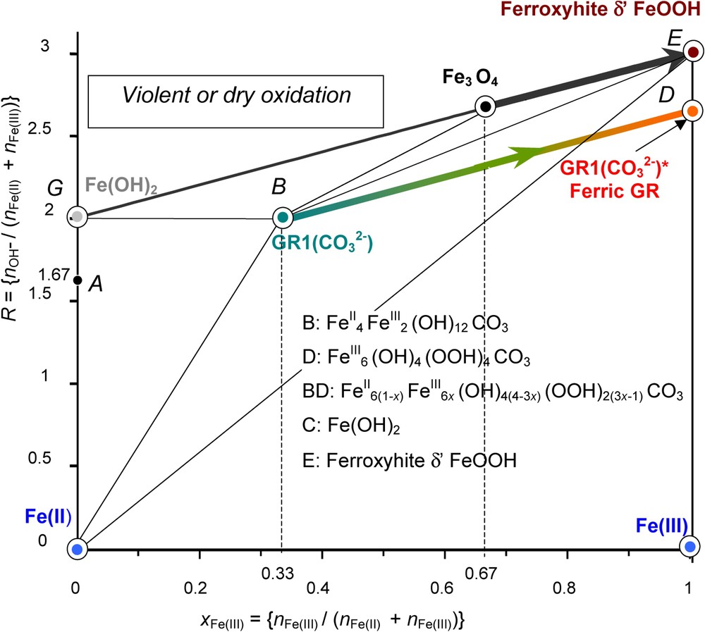
Mass-balance diagram comprising FeII–III hydroxycarbonate green rust GR1() at stoichiometry, i.e. x=1/3 (point B) and ferric GR1()∗ (point D). The path followed during the fast oxidation of GR1() by H2O2 is stressed. The final ferric oxyhydroxide is the fully deprotonated green rust GR1()∗. A similar deprotonation process may occur with Fe(OH)2 to form δ-FeOOH-feroxyhyte mineral.
Diagramme bilan matière comportant l'hydroxycarbonate ferreux–ferrique GR1() rouille verte à la stœchiométrie, c'est-à-dire x=1/3 (point B) et sa forme ferrique GR1()∗ (point D). Le chemin suivi au cours d'une oxydation rapide de GR1() par H2O2 est souligné. L'oxyhydroxyde ferrique final est la « rouille verte » complètement déprotonée, de couleur orange, GR1()∗. Un processus similaire de déprotonation peut survenir avec Fe(OH)2 pour former le minéral feroxyhyte δ-FeOOH.
The same type of phenomenon occurs if oxidising violently Fe(OH)2 with H2O2. A phase named δ-FeOOH forms. Its mineral counterpart is feroxyhyte [4]. In both cases, the original crystal lattice is conserved; each FeII(OH)6 octahedron becomes a FeIII(OOH)3 octahedron while the FeII gets oxidised. Reactions are quite similar as shown in the mass-balance diagram (Fig. 7). Starting at point G , Fe(OH)2 for ferrous hydroxide, one ends at point E , δ-FeOOH for feroxyhyte, by consuming some OH− and following path GE according to:
| (4) |
For its part, the fast oxidation of GR1() that starts at B and ends at D with also a consumption of OH− follows accordingly path BD:
| (5) |
3.2 Voltammetry
Voltammetric curves have been drawn to form GR1() and obtain electrode potential data by using an iron foil [11]. The curve is reversible and a hysteresis occurs in situ during oxidation and reduction (Fig. 8a). SEM picture displays hexagonal orange ferric GR1()∗ crystals (Fig. 8b); a continuum exists where x lies all over the interval. Using voltammetric curves is common in corrosion science giving valuable information. In this extremely important case – since it deals with the corrosion of iron-made materials and steels –, products and processes can be quite different, due to the various conditions of oxidation that can be encountered. This renders any prediction more difficult.
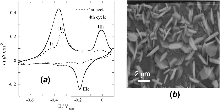
(a) Voltammograms obtained on iron disc at 10 mV s−1 in 0.4 M NaHCO3 solution at 25 °C and pH=9.6. (b) SEM image of the orange ferric compound resulting from the oxidation by air of electrochemically formed GR2() after ageing at 30 °C for 50 days.
(a) Voltampérogrammes obtenus avec un disque de fer à 10 mV s−1 dans une solution 0,4 M NaHCO3 à 25 °C et pH=9,6. (b) Image au microscope à balayage du composé ferrique orange résultant de l'oxydation à l'air de GR2() formée électrochimiquement après vieillissement de 50 jours à 30 °C.
4 Reduction of FeOOH
The mass-balance diagram was very useful for illustrating the three reaction stages that evolve during the oxidation processes of Fe(OH)2 as discussed previously for aerial oxidation, i.e. by following initially (stages A and B) a straight line of slope 1 (Figs. 3 and 6). Similarly, a fast oxidation as accomplished by using H2O2 gave rise to a deprotonation of GR, the ‘ferric GR∗’ and the pathway followed also a line of slope 1 from B to D as drawn for the carbonated medium (Fig. 7). How to materialise the pathways when starting from the ferric oxyhydroxides? From point E that represents FeOOH, there are three possibilities (Fig. 9): (i) the dissolution of FeIII in an acidic medium illustrated by a vertical line EI, , that is the tie-line between solid FeOOH and Fe3+ ions, (ii) a reductive dissolution following line EF of slope 3 that represents a mixture of FeOOH and Fe2+ ions in solution, (iii) a reduction of the solid phase following line EH of slope 1 that reaches Fe3O4.
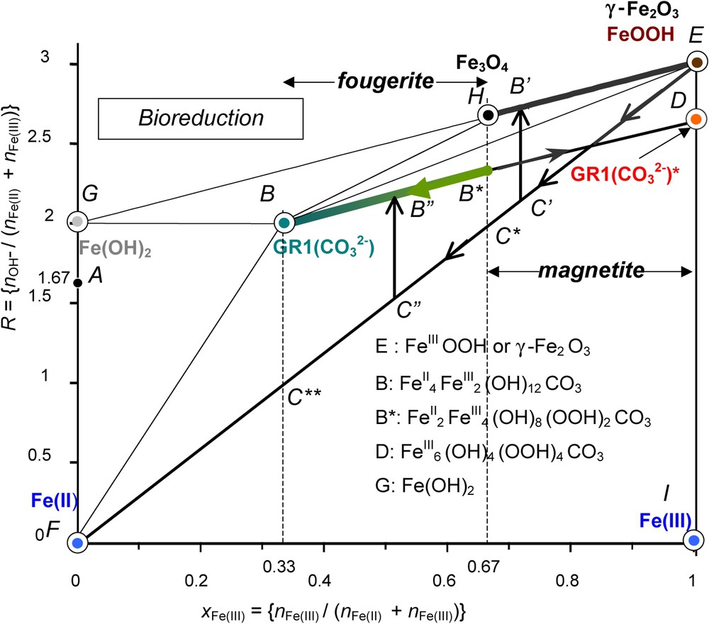
Mass-balance diagram including FeII–III hydroxycarbonate green rust GR1() at stoichiometry, i.e. x=1/3 and ferric GR1()∗. The paths followed during the bacterial reduction of any ferric oxyhydroxide by dissimilatory iron reducing bacteria (DIRB) are stressed demonstrating that magnetite or partially deprotonated hydroxycarbonate may form depending on the bacterial activity. Fougerite is GR1()∗ in the range (1/3)⩽x⩽(2/3), whereas magnetite is in the range (2/3)⩽x⩽1.
Diagramme bilan matière de l'hydroxycarbonate ferreux–ferrique GR1() rouille verte à la stœchiométrie, c'est-à-dire x=1/3 et GR1()∗ ferrique. Les cheminements suivis au cours de la réduction bactérienne d'un quelconque oxyhydroxyde ferrique par les bactéries ferriréductrices dissimilatives sont soulignés, montrant que la magnétite ou l'hydroxycarbonate partiellement déprotoné peut se former selon l'activité bactérienne. La fougérite se trouve dans le domaine (1/3)⩽x⩽(2/3), alors que la magnétite se trouve dans le domaine (2/3)⩽x⩽1.
4.1 Bioreduction of ferric oxyhydroxides
The second pathway EF is followed during the dissimilatory reduction of FeOOH by bacteria (Fig. 9) [12]. The practical role of DIRB is to reduce ferric species from solid state into Fe2+ ions that are dissolved in circumneutral medium by enzymatic activity [20,21]. This produces a mixture of Fe2+ and FeOOH and the running point migrates from E to F (Fig. 9).
The precipitate that forms depends on the position at which the mixture of FeOOH and FeII is located before a coprecipitation occurs in relation with the pH of the solution through the value of R. From E to C∗ where , only off-stoichiometric magnetite may form following line to (Fig. 9). From C∗ to C∗∗, only GR1()∗ forms by coprecipitation () in circumneutral conditions. The domain of biogenerated hydroxycarbonate corresponds to and the reaction is:
| (6) |
4.2 The FeII–III hydroxycarbonate fougerite
Occurrences of GRs in the Gr horizon of a gley soil are consistent with the previous scheme. The mineral is formed by bacterial reduction of ferric oxyhydroxides [8]. Carbonate and FeII ions come from the consumption and decomposition of humic substances, and the respiration of bacteria. Route of Fig. 9 is followed, giving rise to partially deprotonated GR1()∗ where x belongs to the interval. All fougerite minerals identified up today display Mössbauer spectra where x belongs to this interval.
Therefore, fougerite is where . Some minor substitution of FeII and FeIII by MgII and AlIII in Nature cannot be excluded.
5 –pH Pourbaix diagrams of green rusts
Monitored aerial oxidation of Fe(OH)2 was extensively utilised for preparing GRs, but also for determining their composition [5,6,14,17]. The preparation by coprecipitation of FeII and FeIII species has now supplanted it [2,22,23]. However, one major advantage of disposing of the and pH vs. time curves is that equilibrium data for various concentrations of the solution allowed us to obtain the –pH diagrams. Fig. 10 displays the Pourbaix diagrams of the 3 major GRs, i.e. GR1() [5], GR1(Cl−) [14] and GR2() [6] from data collected over the years. Water molecules have been suppressed and formulae are set at Fe6(OH)12CO3, Fe4(OH)8Cl and Fe6(OH)12SO4. Table 1 gathers the equations of the various reactions in the Pourbaix diagram, which are extensively used in corrosion studies but also for predicting thermodynamic possibilities to reduce other species in natural environments [7].
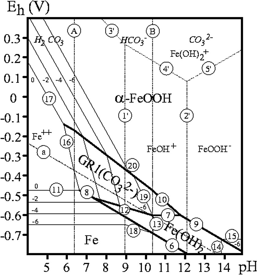


–pH Pourbaix diagrams for (a) carbonate-, (b) chloride- and (c) sulphate-containing medium where GR1() [5], GR1(Cl−) [14] and GR2() [6] have formulae set at Fe6(OH)12CO3, Fe4(OH)8Cl and Fe6(OH)12SO4, respectively. The concentrations of anion species are noted (−n) meaning .
Diagrammes de Pourbaix –pH pour les milieux contenant (a) des carbonates, (b) des chlorures et (c) des sulfates, où GR1() [5], GR1(Cl−) [14] et GR2() [6] ont des formules établies respectivement à Fe6(OH)12CO3, Fe4(OH)8Cl et Fe6(OH)12SO4. Les concentrations en espèces anioniques sont désignées par (−n), signifiant .
Equilibrium equations of Eh–pH Pourbaix diagram reactions for various green rusts: GR1() [5], GR1(Cl−) [14] and GR2() [6]. Formulae are established without water molecules as: Fe6(OH)12CO3, Fe4(OH)8Cla, Fe6(OH)12SO4, respectively (cf. Fig. 9)
Équations d'équilibre des réactions de diagrammes de Pourbaix –pH pour diverses rouilles vertes : GR1() [5], GR1(Cl−) [14] et GR2() [6]. Les formules sont établies sans molécules d'eau, comme étant respectivement : Fe6(OH)12CO3, Fe4(OH)8Cla, Fe6(OH)12SO4 (cf. Fig. 9)
| Water/Eau | |
| (a) | |
| Carbonate species/Espèces carbonatées | |
| (A) | |
| (B) | |
| Iron species/Espèces du fer | |
| (1) | |
| (2) | |
| (3) | |
| (4) | |
| (5) | |
| (6) | |
| (7) Carbonate-containing medium/Milieu contenant des carbonates | |
| (a) | |
| (b) | |
| (7) Chloride-containing medium/Milieu contenant des chlorures | |
| (7) Sulphate-containing medium/Milieu contenant des sulfates | |
| (8) Carbonate-containing medium/Milieu contenant des carbonates | |
| (8) Chloride-containing medium/Milieu contenant des chlorures | |
| (8) Sulphate-containing medium/Milieu contenant des sulfates | |
| (9) | |
| , with E°=0.097 and 0.197 V for α- and γ-FeOOH, respectively | |
| (10) Carbonate-containing medium/Milieu contenant des carbonates | |
| (a) | |
| (b) | |
| (c) | |
| (10) Chloride-containing medium/Milieu contenant des chlorures | |
| (10) Sulphate-containing medium/Milieu contenant des sulfates | |
| (11) | |
| (12) | |
| (13) | |
| (14) | |
| (15) | |
| , with E°=−1.08 and −0.98 V for α- and γ-FeOOH, respectively. | |
| (16) Carbonate-containing medium/Milieu contenant des carbonates | |
| (a) | |
| (b) | |
| (16) Chloride-containing medium/Milieu contenant des chlorures | |
| (16) Sulphate-containing medium/Milieu contenant des sulfates | |
| (17) | |
| , with E°=0.89 and 0.99 V for α- and γ-FeOOH, respectively. | |
| (18) | |
| (19) Carbonate-containing medium/Milieu contenant des carbonates | |
| (19) Chloride-containing medium/Milieu contenant des chlorures | |
| (19) Sulphate-containing medium/Milieu contenant des sulfates | |
| (20) | |
| , with E°=0.35 and 0.45 V for α- and γ-FeOOH, respectively. |
6 Conclusion
The aerial oxidation of Fe(OH)2 in the presence of anions, e.g., Cl−, or depends strongly on the initial value of R={[OH−]/[Fetotal]}. At stoichiometry of Fe(OH)2, i.e. at , only two plateaus are observed whatever the anions and pH starts around 9 to drop down to about 4–5; the final product is magnetite, which hardly evolves to maghemite. In contrast, with an excess of FeII and typically for , three plateaus A, B and C are observed, each corresponding to a reaction equilibrium: in A, between Fe(OH)2, and GR(), in B, between GR(), and FeOOH, and in C, between , FeOOH and , e.g., for , or , FeOOH, e.g., for , depending on the pH of the solution due to the dissolved anion. GRs appear in circumneutral conditions (Fig. 10) thus playing a major role in the corrosion of steels and natural environments. The ratio x={[FeIII]/[Fetotal]} cannot exceed 1/3 for an ordered structure and x belongs to . The general formula of GRs is , with .
Other ways of oxidation, e.g., fast oxidation by H2O2, dry oxidation or voltammetry give rise to a deprotonation of the GR in situ, which can be complete, giving the ‘ferric GR’ that keeps essentially the initial structure. Biotic reduction of ferric oxyhydroxides by DIRB leads also to partially deprotonated GR1()∗ but the range is limited to due to a competition with magnetite. It is , which renders the fougerite mineral isomorphous with pyroaurite and hydrotalcite, belonging to the space group.


