

1 Introduction
Chalcogenide glasses are based on the chalcogen elements S, Se and Te and the addition of other elements such as Ge, As and Sb leads to the formation of stable glasses 〚1〛. The addition of halides leads to the formation of chalcohalide glasses 〚2〛. Examples of stable glasses include As2S3 〚1〛, Ge20S40Br40 〚2〛, As2Se3 〚1〛, and Ge30As10Se30Te30 〚3〛. More recent efforts have reported on rare earth doping for active applications and consequently alternative glasses have been developed. Examples of these glass systems include Ge–Ga–S 〚4〛, Ge–As–Ga–S 〚5〛, Ga–La–S 〚6〛, Ga–Na–S 〚7〛, Ge–S–I 〚8〛, and Ge–As–Se 〚9〛.
Since the chalcogenide glasses transmit to longer wavelengths in the IR than silica and fluoride glasses (Fig. 1), there are numerous potential applications in the civil, medical and military areas. These can be essentially divided into two groups, namely ‘passive’ and ‘active’ applications:
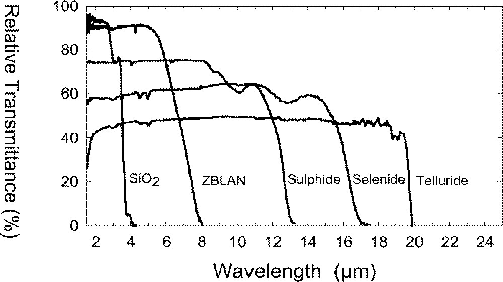
Transmission spectra for several glasses (thickness of about 2–3 mm).
Passive applications. The fibers are used as a light conduit from one location to another without interacting with the light, other than that due to scattering, absorption and end face reflection losses associated with the fiber.
Active applications. The light propagating through the fiber is modified by a process other than that due to scattering, absorption and end face reflection losses associated with the fiber. Examples of these include fiber lasers, amplifiers, bright sources, gratings and non-linear effects.
This paper describes the properties of the chalcogenide glass fibers and some of the applications being developed in our laboratory and worldwide.
2 Experimental techniques for preparing fibers
Chalcogenide glasses are either melted directly in quartz ampoules or in vitreous carbon crucibles located within quartz ampoules. Typical melt temperatures range from 600 to 1100 °C, depending upon composition. The liquids are quenched and the glass rods annealed at temperatures around the appropriate softening temperatures. The optical fibers are obtained by heating preforms fabricated via rod-in-tube type processes 〚10, 11〛 or by double crucible (DC) processes 〚11–13〛. The cladding tubes can be obtained via an in-situ casting process, which is preferred due to less contamination and higher quality surfaces, or by core drilling from larger samples which typically leads to a rough surface quality. The preforms can also be obtained by extrusion of core and cladding glass billets 〚7〛. The DC process enables adjustments to be made in the core/clad diameter ratio during fiber drawing by independent pressure control above each melt. Therefore both multimode and single mode fibers can be drawn with relatively fewer processing steps using the DC process.
There has been much work on determining the origin of the extrinsic scattering centers and absorption impurities and consequently numerous purification techniques based on distillation and sublimation of precursors and glasses have been developed to reduce their contribution to the total optical loss of the fiber 〚14–16〛.
3 Results and discussion
3.1 Properties of fibers
Table 1 lists some physical, mechanical and optical properties of two chalcogenide glasses used in making optical fibers 〚17〛. Compared to the more traditional oxide glasses, they can be described as having lower Tgs, higher CTEs, lower hardness and higher indices of refraction 〚17〛. From a practical viewpoint, the most important difference is their longer wavelength transmission. Figs. 2a and b show the transmission spectra of three chalcogenide fibers made in the authors’ laboratory as a function of precursor quality. The fibers in Fig. 2b were made using distillation and sublimation of the precursors 〚16〛. Depending upon composition, the sulfide, selenide and telluride based fibers transmit between about 0.8–7 μm, 1–10 μm, and 2–12 μm, respectively. Therefore, the practical applications dictate the type of fiber to be used. The As–S fibers have received the most attention to-date in our laboratory and so the loss routinely achieved is about 0.1–0.2 dB m–1 in fiber lengths of about 500 m. Comparing Figs. 2a and b, it is apparent that both purification and composition play an important role in making low loss fibers. Fig. 3 compares the losses routinely obtained for a couple of chalcogenide glasses along with the lowest (‘champion’) losses reported in the literature 〚3, 15〛.
Some physical, mechanical and optical properties of chalcogenide glasses used for making optical fibers.
| As40S60 | Ge30As10Se30Te30 | |
| Physical properties | ||
| Tg (°C)a | 197 | 265 |
| CTE (10–6 °C–1)b | 21.4 | 14.4 |
| Thermal conductivity (W m–1 °C–1) | 0.17 | ∼0.2 |
| Mechanical properties | ||
| Density (g cm–3) | 3.20 | 4.88 |
| Knoop hardness (kg mm–2) | 109 | 205 |
| Fracture toughness (MPa m1/2) | ∼0.2 | ∼ 0.2 |
| Poisson’s ratio | 0.24 | ∼ 0.26 |
| Young’s modulus (GPa) | 16.0 | 21.9 |
| Optical properties | ||
| Refractive indexc | 2.415 (3.0) | 2.80 (10.6) |
| dn/dT (10–5 oC–1)c,d | +0.9 (5.4) | +10.0 (10.6) |
| Bulk transmission (μm) | 0.6–10.0 | 1.0–17.0 |
| Fiber transmission (μm) | 0.8–6.5 | 3.0–11.0 |
| Lowest loss (dB km–1)c | 23 (2.3) | 110 (6.6) |
| Typical loss (dB km–1)c | 100–200 (2.2-5.0) | 500–1000 (6.0-9.0) |
| Estimated minimum loss (dB km–1)c | 1.0 | nd |
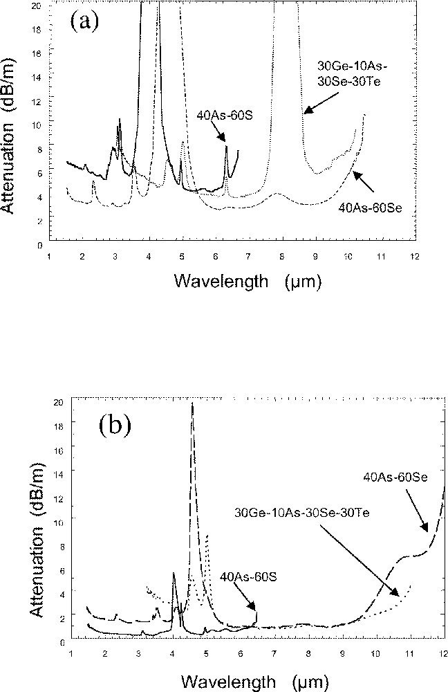
Transmission loss spectra of chalcogenide glass fibers, (a) without purification of chemicals and (b) after purification of chemicals.
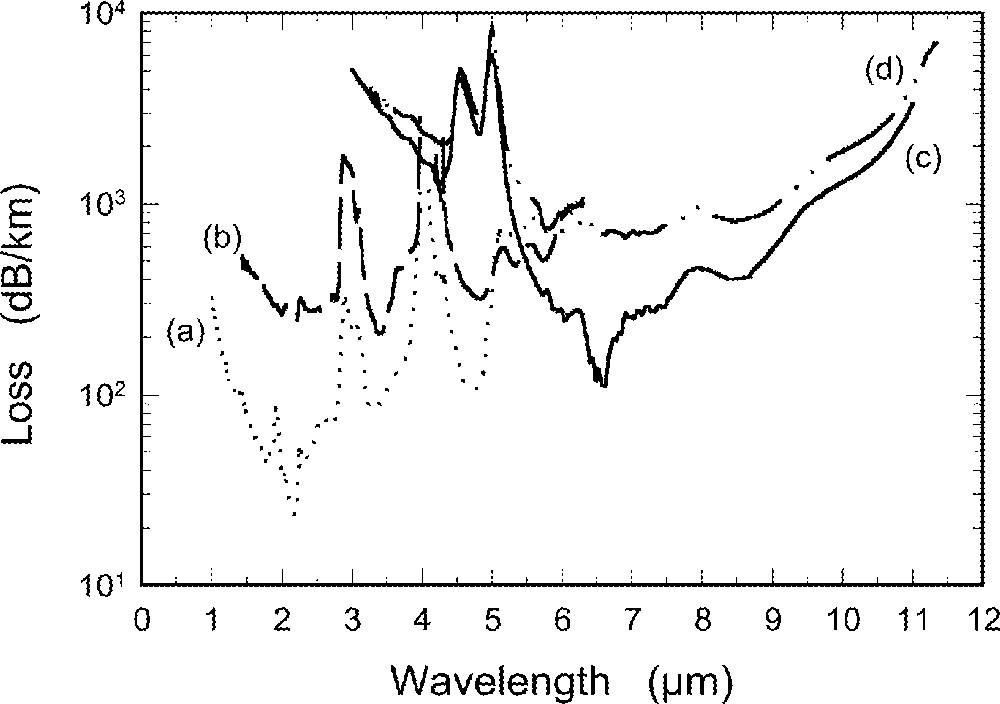
Transmission loss spectra of (a) lowest loss sulfide fiber, (b) typical sulfide fiber, (c) lowest loss telluride fiber, and (d) typical telluride fiber.
The question arises as to what is the origin of the extrinsic scattering and absorption losses, and furthermore, how can these impurities be removed. The scattering centers have been previously identified as bubbles and particles of SiO2 and carbon and their contribution to the scattering loss has been rigorously analyzed 〚14〛. Despite this, the concentration of these species has not been experimentally determined. On the other hand, the absorbing species have been quantitatively characterized 〚16〛. Table 2 lists the estimated concentration of typical absorbing impurities found in sulfide and telluride fibers 〚16〛. Although the losses of the fibers are routinely higher than the champion values, it is worthwhile to estimate the theoretical minimum loss. This has been done for an arsenic sulfide glass 〚16〛 and the results are shown in Fig. 4. The minimum loss is estimated to be about 4 dB km–1 at 5.0 μm 〚16〛. The minimum loss obtained for a 400-ppm Dy-doped unclad selenide glass fiber was 0.8 dB m–1 at 6.6 μm and 3 dB m–1 at 1.3 μm. Multimode fiber has been drawn with a loss of 6 dB m–1 at 1.33 μm and a minimum loss of about 3 dB m–1 at approximately 6 μm. The losses for Pr doped fibers are similar. Undoped samples have been fabricated into single-mode fibers (core/cladding diameters = 4/110 μm) with losses of 3 dB m–1 at 1.55 μm. In general, typical measured losses for the rare earth doped glasses are > 0.5 dB m–1 and so improvements in purification and fiberization technology are still needed to reduce the measured optical losses. Although the losses of the sulfide fibers are routinely higher than both the ‘champion’ and the estimated theoretical values, these fibers can be, and are being used in numerous applications. Unfortunately, theoretical estimates are not available for other glass systems, but despite this, the selenide, telluride and rare earth doped glass fibers are being fabricated and utilized in numerous applications.
Estimated concentration of typical impurities in sulfide and telluride fibers 〚16〛.
| Impurity absorption | Wavelength | Absorption loss | Extinction coefficient | Impurity concentration |
| (μm) | (dB m–1) | (dB m–1 ppm–1) | (ppm) | |
| Sulfide fibers | ||||
| H–S | 4.0 | 10 | 2.3 | 4.3 |
| O–H | 2.9 | 0.3 | 5.0 | 0.06 |
| Telluride fibers | ||||
| H–Se | 4.5 | 3.0 | 1.1 | 2.7 |
| Ge–H | 5.0 | 6.0 | — | — |
| H2O | 6.3 | 0.07 | 34.0 | 0.002 |
| Ge –O | 7.9 | 0.16 | 2.6 | 0.06 |
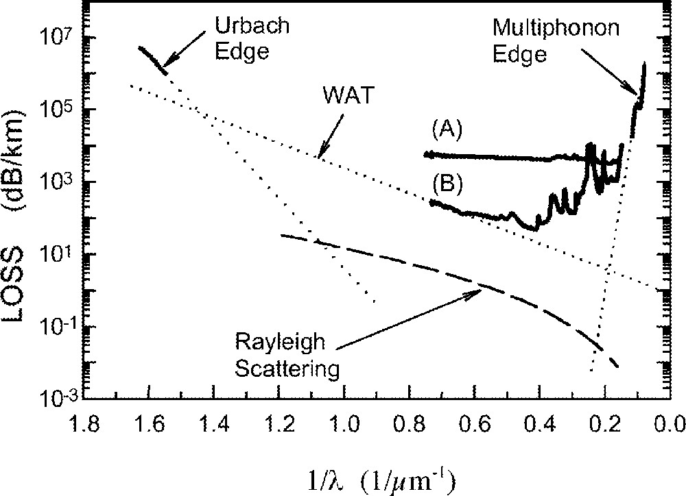
Estimation of theoretical minimum loss in a sulfide fiber. A and B represent poor- and high-quality glasses, respectively 〚16〛.
Tables 3 and 4 list the passive and active applications of chalcogenide glass fibers, respectively, which have been demonstrated or are being investigated. These will be discussed in more detail in the next section.
Passive applications of IR transmitting chalcogenide glass fibers.
| Applications | References |
| Laser power delivery | |
| • 5.4 μm (CO) | 〚18, 19〛 |
| • 10.6 μm (CO2) | 〚18, 19〛 |
| • Atmospheric 2–5-μm region | 〚20, 21〛 |
| • Medical free electron laser (2–10 μm) | 〚22, 24〛 |
| • Anti-reflection (AR) coatings | 〚19, 20〛 |
| Chemical sensing | |
| • Aqueous, non-aqueous, toxic chemicals | 〚25–29〛 |
| • Polymers, paints, pharmaceuticals | 〚11, 28, 30〛 |
| • Condition based maintenance (CBM) | 〚28〛 |
| • Cone penetrometer system | 〚31〛 |
| • Active coatings | 〚32〛 |
| • Bio-medical | 〚22, 33〛 |
| Temperature monitoring | |
| • Grinding ceramics | 〚34〛 |
| Thermal imaging & hyperspectral imaging | |
| • Coherent fiber bundles | 〚35–37, 39〛 |
| Near-field microscopy | |
| • Imaging and spectroscopy | 〚40–42〛 |
| Fiber multiplexing | |
| • Fiber couplers | 〚43〛 |
Active applications of IR transmitting chalcogenide glass fibers.
| Applications | References |
| Rare-earth doped fibers: | |
| • Fiber lasers: 1.08 μm (Nd) | 〚55〛 |
| • Amplifiers: | |
| 1.08 μm (Nd) | 〚56〛 |
| 1.34 μm (Pr) | 〚7〛 |
| 1.34 μm (Dy) | 〚54〛 |
| • Infrared scene simulation (IRSS) | 〚59〛 |
| • Chemical sensing | 〚22〛 |
| • Gratings: 1.5 μm | 〚63–65〛 |
| Non-linear | |
| • Optical switching | 〚68–70〛 |
| • Second harmonic generation | 〚72, 74〛 |
| • Frequency mixing | — |
| • Electrical poling | — |
| • Raman amplification | 〚75〛 |
3.2 Passive applications
3.2.1 Laser power delivery
High-power CO and CO2 lasers operating at 5.4 μm and 10.6 μm, respectively, are readily available and can be used for industrial welding and cutting. Transmitting the laser power through fibers enables remote operation. Small core diameter (< 200 μm) fibers have demonstrated tolerance to power densities of ∼125 kW cm–2 at 5.4 μm and ∼54 kW cm–2 at 10.6 μm without damage 〚18〛 (Fig. 5a and b). Telluride glass fiber losses at 10.6 μm lie in the range of 1.5 dB m–1 to 3 dB m–1, depending upon composition and purity 〚3, 19〛.
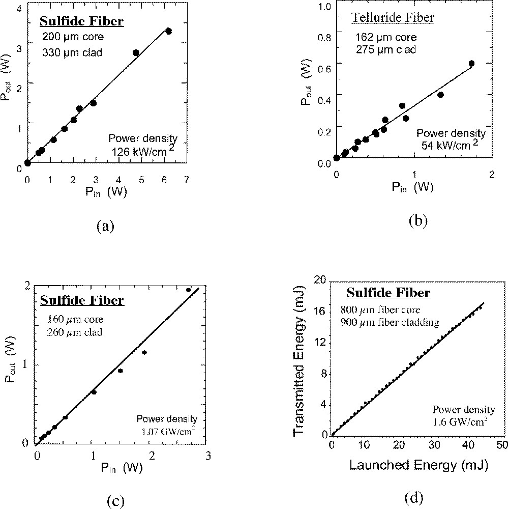
(a) CO-laser transmission, (b) CO2-laser transmission, (c) pulsed high-energy laser transmission in the 2–5 μm region, and (d) free-electron laser energy transmission.
The arsenic sulfide fibers transmit in the atmospheric 2–5 μm region and can be used for transmission of laser power in this region 〚20〛. Pulsed laser power delivery has been demonstrated (Fig. 5c). The average power is about 2.69 W but the peak power is 26.9 kW, which corresponds to a peak power density of 1.07 GW cm–2 without fiber damage for up to 1.5 × 10⁷ pulses 〚21〛. This remarkable threshold to damage is close to the predicted value of about 3.0 GW cm–2 due to dielectric breakdown at the surface. This threshold to damage is obtained by control of fiber polishing, otherwise the fiber end face undergoes damage at relatively lower powers.
Recent efforts have considered delivery of energy from a medical free electron laser (MFEL) operating between 2 and 10 μm through chalcogenide fiber 〚22, 23〛. The MFEL can emit more than 10 MW of power in a femtosecond pulse that relates to an average power of greater than 10 W. While not all this power is needed, it has been shown 〚24〛 that in certain cases, surgery at 6.1 and 6.45 μm based on cleaving of protein bonds is more efficient and leads to less denatured tissue and scarring than with conventional Er:YAG lasers at 2.94 μm based on OH absorption 〚24〛. We have successfully demonstrated (Fig. 5d) almost 18-mJ output at 6.1 μm (43 mJ launched) and 12-mJ output at 6.45 μm (30 mJ launched) using large core diameter (800 μm) sulfide and selenide fibers, respectively 〚23〛. The peak power densities were 1.6 and 1.2 GW cm–2, respectively. While these fibers were not AR coated, it is expected that future AR coated fibers will enable higher output energies. Ophthalmic surgery requires operation at 2.94 μm, with an energy requirement of 1–2 mJ. This has been demonstrated using chalcogenide fibers. Output energy from an Er:YAG laser operating at 2.94 μm has been transmitted through sulfide fiber. Up to 271 kW cm–2 power density has been transmitted without damage to the fiber. It is conceivable that laser power can be used for machining numerous materials and biological samples by tuning the wavelength and transmitting the laser power through the chalcogenide fibers to remote areas.
The end face reflection losses decrease the overall throughput of laser power. For example, As40S60 and Ge30As10Se30Te30 glasses have refractive indices of about 2.4 and 2.8, for which reflection losses are about 17% and 22% per face, respectively. Consequently, AR coatings are being developed for both discrete wavelengths as well as broadband operation 〚19, 20〛. Reflection losses have been reduced to about 1% per face for sulfide fibers at some IR wavelengths 〚20〛.
3.2.2 Chemical sensing
Chalcogenide fibers are well suited for chemical sensing applications since most molecular species vibrate in the infrared region. The chalcogenide fibers can be used in fiber optic chemical sensor systems for quantitative remote detection and identification. Examples of different sensing techniques include evanescent/ATR (attenuated total reflectance) 〚25–27〛, diffuse reflectance and absorption spectroscopy 〚28–30〛. The diffuse reflectance and evanescent/ATR techniques are useful for samples that scatter or are opaque at the IR wavelengths. Numerous systems have been studied and many species have been detected including aqueous, non-aqueous and toxic liquids as well as solids 〚25–30〛. Examples include oil, freon, soap, paints, polymer curing reactions, glucose/water, benzene and derivatives, chlorinated hydrocarbons, alcohols, carboxylic acids, aqueous acids, perfumes and pharmaceutical products. Fig. 6a shows some representative spectra.
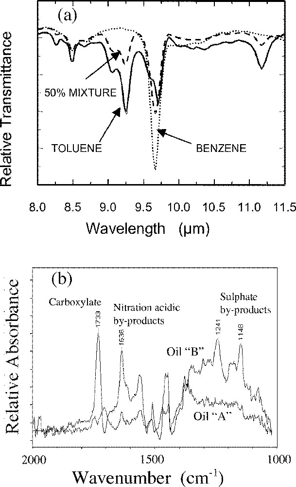
(a) Chemical sensing using IR fibers for a mixture of benzene and toluene and (b) difference spectra of degraded oil (after 〚28〛).
Condition based maintenance (CBM) is becoming increasingly important and uses the approach, “if it isn’t broken, don’t fix it”. For example, changes of oil in motor vehicles are routinely performed every 3000 miles or so, but are not necessarily needed and therefore the incurred costs can be quite significant. A fiber optic dipstick probe could potentially monitor the quality of the oil and consequently save large amounts of money in preventing unnecessary oil changes in the military and civil sector. For example, there is an additive package used to inhibit viscosity breakdown of engine oil. Unfortunately, environmental breakdown of the additive package occurs and leads to viscosity breakdown of the oil. A fiber optic dipstick can be used to monitor the by-products of degradation of the additive package (Fig. 6b). The alarm bells sound when these reach a pre-determined threshold value, signaling an oil change.
A fiber optic based reflectance probe has been used to detect contaminants in soil (Fig. 7) 〚31〛. The detection was accomplished with the probe deployed in a cone penetrometer and tested in the field. Detection limits of 130 ppm of marine diesel fuel in sea sand have been demonstrated using a 20-m length of cable 〚31〛.
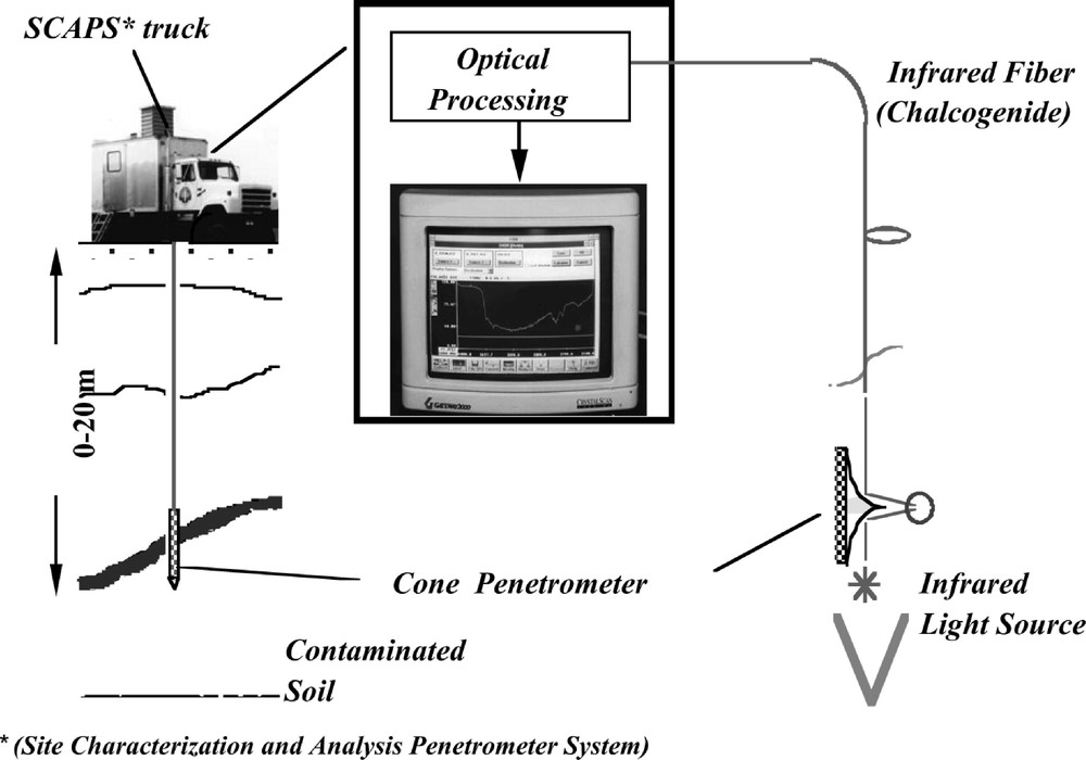
The cone penetrometer system using chalcogenide fiber for detection of contaminants and water in soil.
Chalcogenide fibers with a glass cladding have been used for evanescent sensing of a few tens of ppm of benzene (and derivatives) and chlorinated hydrocarbons. The low detection limits were achieved by etching the cladding glass and re-covering with specific polymer coatings that preferentially enrich one phase in them near the core surface 〚32〛. Polydimethylsiloxane (PDMS) preferentially enriched benzene (and derivatives) and low-density polyethylene enriched the chlorinated hydrocarbons on the core surface while preventing water from penetrating the coating.
Recently, a chalcogenide fiber ATR probe has been used to show the spectral differences between various tissues and organs in bio-medical samples. Fig. 8a shows the IR spectra for various organs/tissues from a dead chicken, while Fig. 8b shows the IR spectrum recorded from the liver of an anaesthetized sheep 〚22〛. Similar IR spectra have been recorded from an anaesthetized mouse with a malignant (cancer) human breast tumor grown near the surface. While these data were recorded using chalcogenide glass in contact with tissue, alternative IR transmitting and biocompatible probes will most likely be needed for human testing. However, the chalcogenide fibers can be utilized to generate a bio-medical database for medical diagnostics such as tissue evaluation and early detection of cancer 〚33〛. Currently, large portions are cut out of the body, prepared into thin sections and desiccated before FTIR analysis is performed. Obviously, the flexible fiber optic approach is minimally invasive. While silica fibers are available they are inappropriate for infrared spectroscopy in the 2–10-μm region.
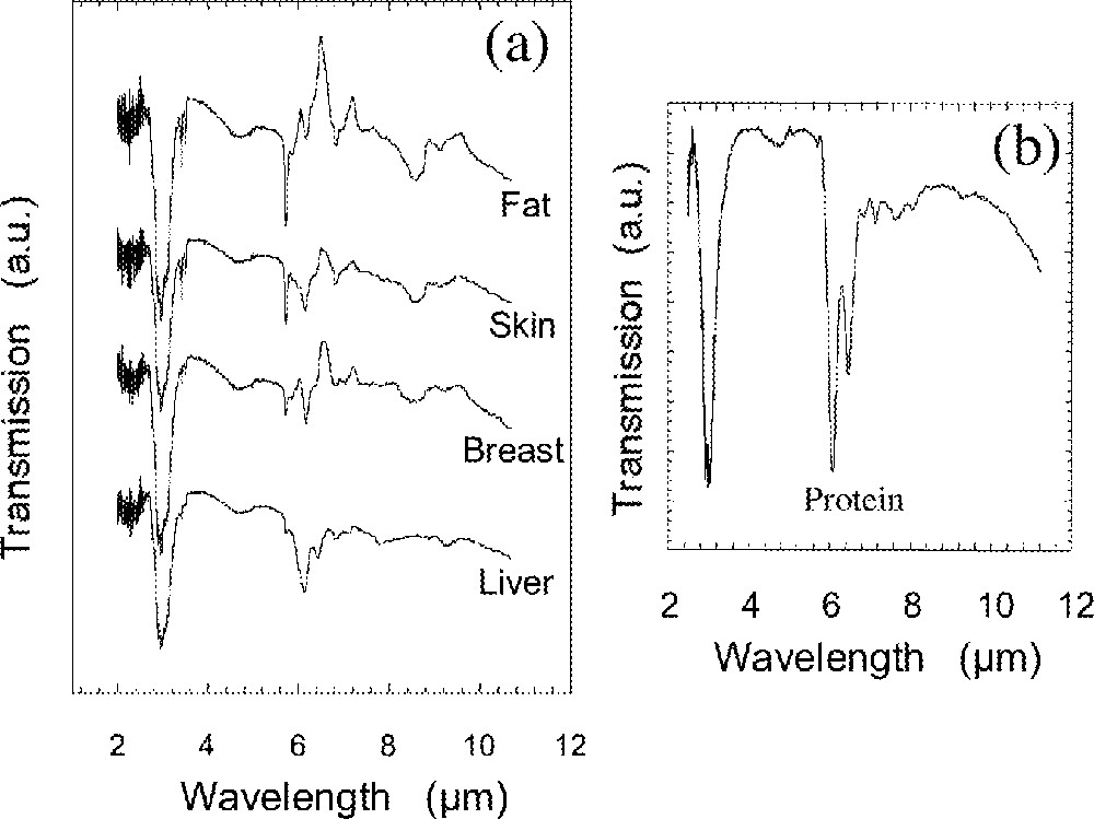
Attenuated Total Reflection (ATR) spectra of (a) chicken tissue/organs and (b) liver of living sheep.
3.2.3 Temperature monitoring, thermal imaging and hyperspectral imaging
Ueda et al. 〚34〛 have used As–S fibers with a Teflon cladding to measure temperature increases of up to 200 °C on the surface layer of ceramic plates during grinding.
Kapany and Simms first suggested the use of chalcogenide fibers for thermal imaging 〚35〛. Saito et al. 〚36〛 recorded the image of an electric iron at 773 K, with some degree of coherency through a 1000-fiber bundle. Nishii et al. 〚37〛 fabricated a flexible fiber bundle containing 8400 Teflon coated fibers and recorded the thermal image of an operating integrated circuit in the 3–5.4 μm region using an InSb detector. Techniques are needed for the fabrication of coherent and registered fiber bundles containing small diameter fiber but with tight tolerances and high precision. Fig. 9 shows the cross-section of an imaging bundle fabricated at NRL using glass clad sulfide fiber that transmits to beyond 5 μm. The bundle diameter was 165 μm and the fiber core diameters were only 6 μm.
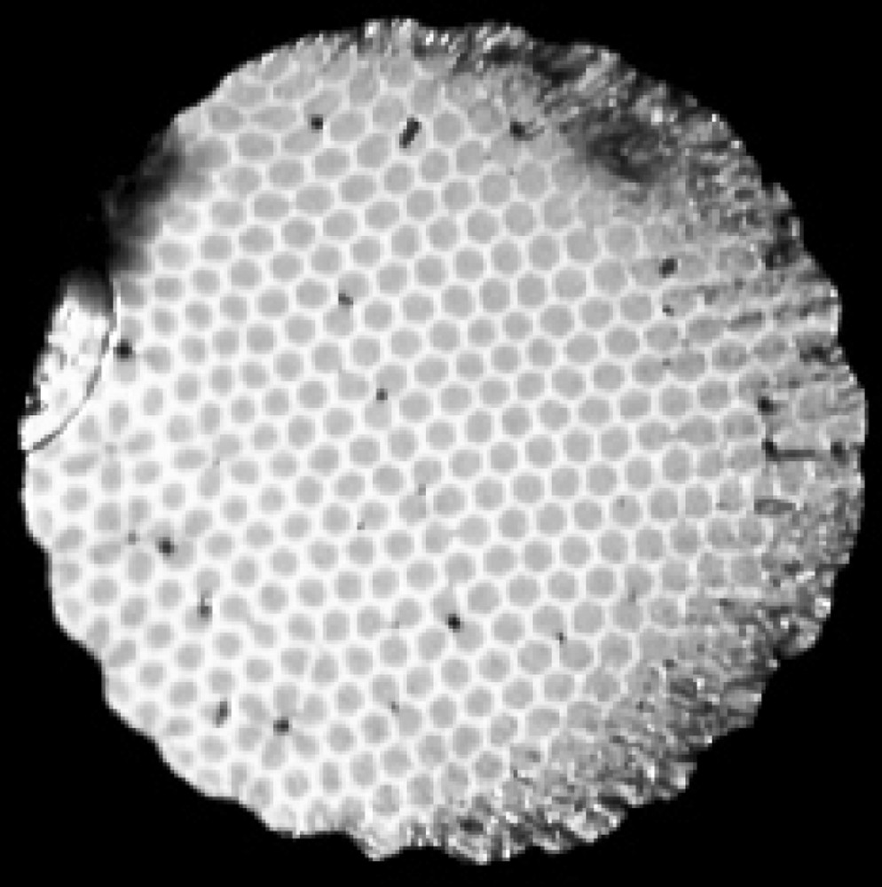
End-face optical picture of an IR fiber imaging bundle containing 427 fibers. The core diameter is 6 μm and the outer diameter is 165 μm.
The area of hyperspectral imaging can be exploited by coupling coherent fiber bundles to imaging spectrometers with focal plane array (FPA) detectors based on InSb (2–5.4 μm) or MCT (3–11 μm). The focal plane array detectors are extremely sensitive and can be used for performing both spatial and spectral analysis in the infrared 〚38〛. In other words, one can derive an IR spectrum from each pixel thereby performing chemical spectroscopy at every pixel. FPA detectors have been used for obtaining spectral and spatial information about the environment for a number of years, but without fibers. The only report in the literature pertaining to IR fibers is a 10 × 10 fiber bundle of As2S3 fiber with a Teflon cladding that was reformatted to a 1 × 100 array and the output analyzed using a grating spectrometer 〚39〛. The intensity contour of a Xenon lamp was recorded. Coupling to FPAs requires high precision diameter and high quality fiber bundles so that each fiber in the bundle couples to only one pixel on the detector otherwise the images will be blurred. Alternatively, many small diameter fibers, as shown in Fig. 9, can be used to couple to a single pixel.
3.2.4 Near-field microscopy
Sub-diffraction limit resolution has been demonstrated using single mode silica fibers by pulling and/or etching the fiber ends from a diameter of 125 μm to below 100 nm at the fiber tip. Preliminary results were obtained using multimode chalcogenide fiber micro-tips with about 1-μm resolution 〚40〛. More recently, the authors have used high-quality single-mode and multimode chalcogenide fibers to demonstrate about 20 nm topographic resolution and about 200 nm spectral resolution for different samples such as polycrystalline diamond 〚41〛, pancreatic cells 〚42〛, biofilms and semiconductor samples. Fig. 10 shows the topographic and optical images for a polycrystalline diamond film and pancreatic cells, respectively. The dark regions highlighted in the optical images are due to absorption by specific molecular vibrations. In our opinion, this is a promising technique for imaging and performing spectroscopy of semiconductor and biological samples with sub-micron resolution.
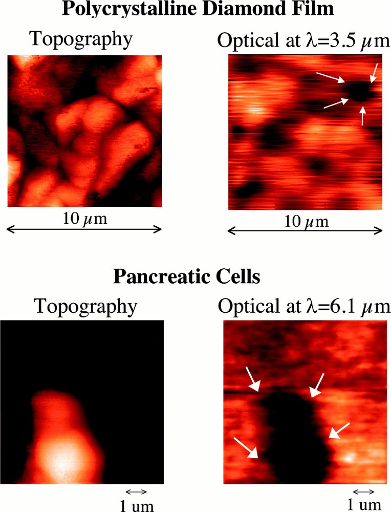
Scanning near field IR microscopic (SNIM) data for pancreatic cells and a polycrystalline diamond film using a selenide fiber micro-tip. The topographic and optical spectra were recorded with a resolution of about 25 nm and 200 nm, respectively.
3.2.5 Fiber multiplexing
Fused fiber couplers are important since they enable fiber multiplexing. For example, they might be used in IR-fiber optic chemical sensing systems and data transmission systems. A preliminary fused taper fiber coupler has been fabricated using a multimode arsenic sulfide fiber with a coupling ratio of 3:1 at 2.65 μm 〚43〛, but it should be possible to use single-mode fibers.
3.3 Active applications
3.3.1 Rare-earth-doped fibers
Rare-earth ions possess characteristic electronic energy levels that are only slightly influenced by the host matrix due to the screening effect of the d electrons. When pumped with the appropriate energy, the electrons are excited into upper levels from which they can subsequently decay to lower levels. Certain transitions become increasingly more efficient in longer wavelength transmitting hosts such as the chalcogenide glasses due to less multiphonon quenching and IR fluorescence emissions beyond 2 μm are only seen in chalcogenide glasses and not in silica. Table 5 lists the IR emission wavelengths found in chalcogenide glasses 〚44–54〛. The only laser oscillation observed in chalcogenide fibers has been from Nd at 1.08 μm 〚55〛 while amplification has been demonstrated using Nd at 1.08 μm 〚56〛 and Pr at 1.34 μm 〚7〛. These results were obtained in sulfide glass hosts. The 1.3-μm wavelength is of interest for telecommunications 〚57〛. The gain coefficient obtained from the single-mode sulfide (Ga–Na–S) fiber at 1.34 μm was a remarkable 0.8 dB mW–1 and the efficiency was about 30%. The fiber loss at 1.34 μm was about 1 dB m–1 〚57〛.
The IR emission wavelengths in chalcogenide glasses and wavelengths that have exhibited laser oscillation and amplification in chalcogenide fibers.
| Rare earth ion | IR emission wavelengths (μm) | Laser oscillation wavelength (μm) | Amplification wavelength (μm) |
| Nd | 0.786, 0.919, 1.08, 1.37 〚43, 44〛 | 1.08 〚55〛 | 1.08 〚56〛 |
| Er | 0.822, 0.860, 0.987 〚45, 46〛, 1.54 〚47〛, 2.7, 3.5, 4.5 〚48〛 | — | — |
| Tm | 1.21, 1.45, 1.81, 2.35 〚49〛 | — | — |
| Ho | 0.76, 0.91 〚46〛, 1.2, 2.9, 3.9 〚50〛 | — | — |
| Pr | 1.3, 1.6, 2.9, 3.4, 4.5, 4.8, 4.9, 7.2* 〚51, 52〛 | — | 1.34 〚7〛 |
| Dy | 1.3, 1.8, 2.3, 4.3 〚53〛 | — | — |
| Tb | 3.0, 4.8, 8.0 〚48, 62〛 | — | — |
Recent work has shown that Dy-doped selenide glasses are better candidates for 1.3-μm fiber amplifiers due to the lower phonon energy of the host glass, and the larger absorption and emission cross-sections for Dy 〚54〛. The quantum efficiency is expected to be about 90% and the gain coefficient approximately double the value for the best Pr-doped sulfide fiber 〚54〛. Modeling has shown that the Dy-doped selenide fiber can tolerate higher losses compared with Pr doped sulfide fibers. Therefore, device lengths will be shorter, such that a 45-cm length of doped selenide fiber with a loss of about 10 dB m–1 can give ∼40 dB gain at 1.34 μm. Table 6 shows some of the properties. Preliminary multimode fibers have been drawn with losses of about 6 dB m–1 at 1.3 μm and less than 3 dB m–1 at about 6 μm 〚58〛. Unclad fibers have been fabricated with losses of about 3 dB m–1 at 1.3 μm and less than 1 dB m–1 at 6 μm. Preliminary single mode fibers have been drawn with minimum losses of about 3 dB m–1 〚58〛.
Branching ratios (β), quantum efficiencies (βη), lifetimes (τ), emission cross-sections (σ) and gain coefficients (στ), for potential 1.3-μm fiber amplifier systems.
| Glass system | β | η (%) | β η (%) | τ (ms) | σ (× 10–20 cm2) | σ τ (× 10–26 cm2 s) |
| Pr: ZBLAN | 0.6 | 3.4 | 2.0 | 110 | 0.35 | 38.5 |
| Pr: GaLaS | 0.52 | 58 | 30 | 295 | 0.84 | 250 |
| Pr: GaNaS | 0.52 | 58 | 30 | 370 | 1.08 | 400 |
| Dy: GaLaS | 0.93 | 29 | 27 | 59 | 2.8 | 165 |
| Dy: GeAsSe* | 0.93 | 95 | 88 | 310 | 2.7 | 837 |
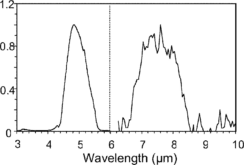
Since the rare earth doped chalcogenide fibers emit in the 2–5-μm region 〚59〛, they are an attractive alternative to blackbody sources for many applications. For example, arrays of the fibers can be used for infrared scene simulation (IRSS) for characterization of focal plane array detectors (e.g., InSb) 〚60〛. Fig. 11 shows the emission spectrum of a Pr-doped selenide glass fiber, demonstrating broadband emission between about 3 and 5 μm. Prototype bundles have been fabricated and mid-IR emission measured from the pixels 〚60〛. Black body temperatures of up to 2400 K have been simulated in single pixel pumping indicating that these fibers are capable of providing bright sources in the IR.
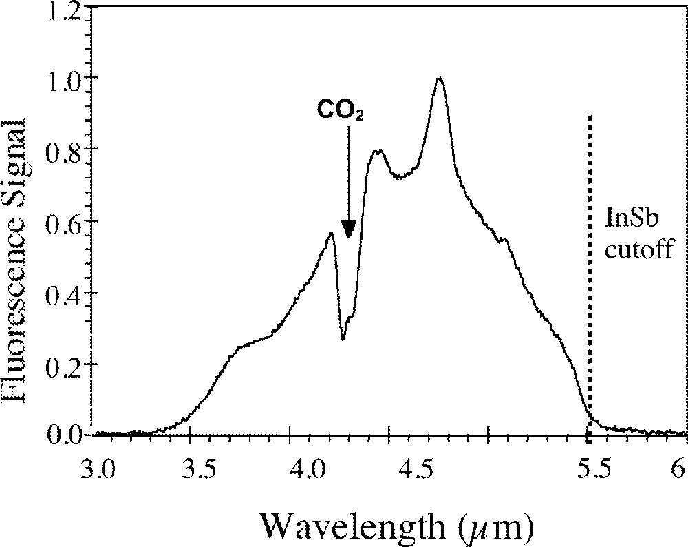
The broadband mid-IR emission from a Pr-doped GeAsGaSe glass fiber.
It is possible to use these fiber sources in chemical sensor systems 〚22〛. For example, Fig. 12 shows the IR transmission spectrum of a thin film of toluene between two CaF2 plates recorded using a Pr-doped selenide fiber (pumped at 1.064 μm) as a mid-IR source 〚61〛.
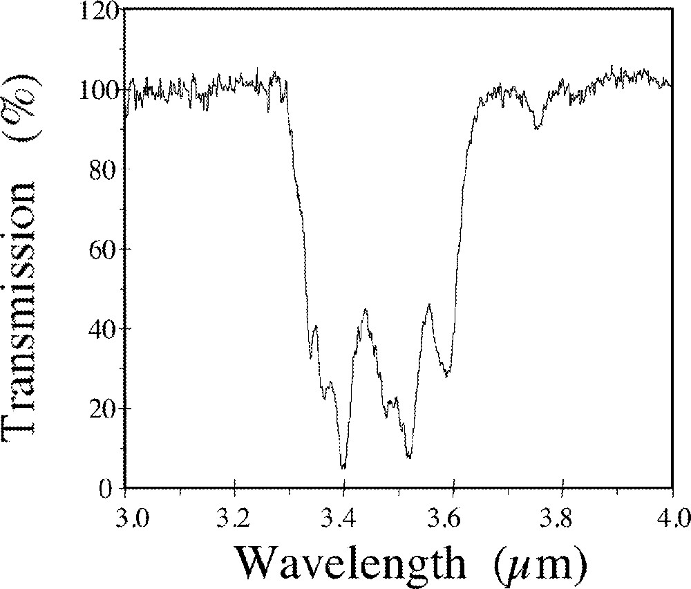
Transmission spectrum of toluene recorded using the mid-IR emission from a Pr-doped GeAsGaSe glass fiber 〚61〛.
Longer wavelength emission from 7–9 μm has been demonstrated in Tb-doped GeAsGaSe and GeAsGaTe glasses. This represents the longest wavelength emission seen from any rare-earth-doped glass or crystal system 〚62〛. Fig. 13 shows the emission spectrum in the 4–5-μm and 7–9-μm regions. The measured lifetimes of the excited state were 12 and 80 μs for the selenide and telluride glasses, respectively.
The mid-IR and long wave fluorescence emission from Tb-doped chalcogenide glass 〚59〛.
The ability to write gratings in chalcogenide fibers will enable smart compact devices including lasers and dispersion compensators. Some work has been performed on writing gratings in chalcogenide glass fibers 〚63–65〛. Asobe et al. 〚63〛 have fabricated an As2S3-based fiber Bragg grating for 1.55-μm-wavelength operation by the transverse holographic method using a He–Ne laser. A reflectivity of > 90% was obtained with an estimated change in refractive index of about 10–4.
3.3.2 Non-linear effects
Glasses possessing high third-order non-linearities (X3) are required for ultra-fast switching in time division multiplexing (TDM) telecommunications systems. It is well established that the values of X3 for chalcogenide glasses are about two orders of magnitude larger than silica 〚66, 67〛. To our knowledge, the number of papers reporting the use of this phenomenon in actual switching applications is not extensive. Asobe et al. 〚68〛 demonstrated efficient optical Kerr shutter (OKS) switching operation with picosecond response time using a 1-m length of elliptical core fiber and a 100-GHz signal operating at a wavelength of about 1.5 μm. More recently, glasses have been reported with non-linearities approaching 1000 times silica 〚69, 70〛. This opens up the potential for compact and integrated all optical switches.
Since glasses lack a center of inversion symmetry and thus have no second order nonlinear susceptibility (X2) they should not exhibit second harmonic generation (SHG) 〚71〛. However, undoped and Pr-doped GaLaS glasses have exhibited SHG 〚72〛 through optical pumping. This SHG may be due to crystallization or the effect of frozen-in electric fields. The latter arises from the relationship X2 = Edc X3, where Edc is the frozen-in electric field 〚71〛. Electric poling has been successfully used to produce SHG in silica based fiber systems 〚73〛 as well as As–S glass film fabricated via evaporation 〚74〛. It is not unreasonable to expect similar results in chalcogenide fibers. Since X3 is about 2 to 3 orders of magnitude larger in chalcogenides compared with silica, we expect larger SHG efficiencies in electrically poled chalcogenide glasses. However, the question arises as to whether the electric fields can be frozen-in for chalcogenide glasses. We have observed preliminary second-harmonic generation using electrically poled arsenic sulfide glass. Fig. 14 shows the observed SHG at 780 nm when pumping a 1-mm thick arsenic sulfide glass disk at 1560 nm. The sample was electrically poled at 100 °C for 5 h under nitrogen gas atmosphere. At the present time, the magnitude appears comparable to silica glass, but the mechanism is unknown.
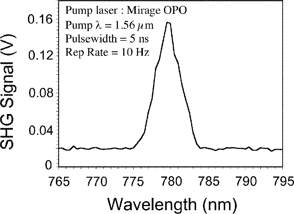
The SHG observed at 780 nm from an electrically poled thin As–S glass disk pumped at 1560 nm.
We have demonstrated Raman amplification in small core As–Se fiber 〚75〛. We observed over 20 dB of gain in a 1.1-m length of fiber pumped by a nanosecond pulse of ∼10.8 W peak power at 1.50 μm. The peak of the Raman gain was shifted by ∼230 cm–1 to 1.56 μm. The Raman gain coefficient is estimated to be about 2.3 × 10⁻¹¹ m W–1, over 300 times greater than that of silica. The large Raman gain coefficient coupled with the large IR transparency window of these fibers shows promise for development of As–Se Raman fiber lasers and amplifiers in the near, mid and long IR spectral regions.
4 Conclusions
Tremendous progress has been made in reducing the optical losses of the chalcogenide glass fibers in the past several years resulting in numerous applications. We strongly believe that IR fiber optics will become increasingly more important in the future as further improvements are made to the quality of the fibers and new compositions developed. One of the most exciting developments in the future is in the area of rare earth ion doping of fibers for IR sources. The IR lasers and amplifiers developed using this phenomenon will be very useful in civil, medical and military applications. Remote IR spectroscopy and imaging using flexible fibers will be realized for medical and military applications. Other future research areas that will inevitably be explored include the fabrication of Bragg gratings in fibers and non-linear optical properties of the IR glasses. The authors strongly believe that chalcogenide glass fiber optics will grow due to the numerous and potentially extensive applications. The availability of high quality, low loss and high strength single-mode and multimode fibers will undoubtedly improve the capabilities of existing technologies as well as enable new technologies. In summary, the future of chalcogenide glasses and fibers looks very bright.
Acknowledgements
The authors would like to acknowledge their colleagues at the Naval Research Laboratory: Vinh Nguyen, Pablo Pureza, Fred Kung, Peter Thielen, Shyam Bayya, Fritz Miklos and Lynda Busse.