

1 Introduction
O'Regan and Grätzel [1] made a major breakthrough in the field of dye-sensitized photoelectrochemical cells in 1991, and opened up the possibility of practical applications as dye-sensitized solar cells (DSCs). A typical DSC comprises a nanocrystalline TiO2 electrode sensitized with a ruthenium dye, a Pt-coated counter electrode consisting of a F-doped SnO2 substrate, and a liquid electrolyte with a I–/ redox couple.
DSCs are attractive for next-generation solar cells because of their potentially high conversion efficiency and the possibility of lower production cost than that of conventional silicon solar cells [2]. However, many things, such as increasing the conversion efficiency even more and achieving better durability, remain to be done before DSCs can be put on the market [3–6]. The electrolyte loss caused by the leakage and/or volatility of the electrolyte solution has been pointed out to be one of the major problem, which stays the durability of the DSC low. Various approaches to the problem have been tried before, and employing polymeric solid electrolytes (PSEs) is one of the most promising approaches. Wang et al. recently employed a PSEs containing 1-methyl-3-propylimidazolium iodide and poly(vinylidenefluoride-co-hexafluoropropylene) (PVDF-HFP) to fabricate a DSC, and a conversion efficiency of the DSC with 0.152 cm2-active area at AM 1.5 illumination stayed at 5.3% [7].
We proposed a PVDF-HFP-based PSE film, having a good ionic conductivity and mechanical strength, for DSCs. The short-circuit current density (Jsc) of the PSE-based DSC has a strong dependence on the cell-gap, and narrower cell-gap gives a higher Jsc. We confirmed experimentally that the Jsc of a PSE-based DSC with a 20 μm cell-gap is turned out to be about 97% of a liquid electrolyte-based DSC [8].
The purpose of this paper is twofold: we discuss the photocurrent of DSCs, with model equations, focusing on the diffusion coefficient of and/or I–, (D0) and the cell-gap, to find a way to achieve a higher conversion efficiency, and also explain the dependence of Jsc on the diffusion coefficient of and/or I– in terms of a back electron transfer process.
2 Experimental
The TiO2 (Ti-nanoxide-T, Solaronix) films formed on a F-doped SnO2 substrate (FTO: TEC15, about 15 Ω sq–1, Pilkington) were 10 μm thick and 5 × 5 mm in size. The TiO2 substrate was sensitized with a ruthenium dye (0.5 mM ruthenium-535-bis-TBA, Solaronix, in EtOH). A 30-nm-thick Pt thin film was deposited on the FTO substrate with the sputtering method, and the FTO substrate was used as a counter electrode. The liquid electrolyte was comprised of 0.5 M 1-propyl-2,3-dimethylimidazolium iodide (DMPII), 0.1 M LiI, 0.05 M I2, 0.5 M 4-tert-butylpyridine (TBP), and one of the following solvents: methoxyacetonitril (MAN), 3-methoxypropionitril (MPN), γ-butyrolactone (GBL), and propylene carbonate (PC). The PSE film consisted of the PVDF-HFP-based matrix polymer and an electrolyte solution (0.5 M DMPII, 0.1 M LiI, 0.05 M I2, and 0.5 M TBP in GBL). The electrolyte content of the PSE film was determined from (m0–md)/m0; m0 and md are the weight of an as-formed PSE film and a dry, solvent-free PSE film, respectively.
The diffusion coefficient of and/or I– in electrolytes were evaluated using the Cottrell equation [9], , where n = 2, F is the Faraday constant, and C0(init) is the initial concentration of . The current–voltage characteristic was measured with a potentiostat (1287 Solartron) under illumination (AM1.5, 100 mW cm–2, surface temperature of the DSC at 27 °C) using solar simulator (YSS-150, Yamashita-Denso) equipped with a cooling stage. The current–voltage curves were measured by using cyclic voltammetry at 10 mV s–1. The cell-gap is defined here as the distance between the surfaces of the FTO and Pt layer. We selected a cell-gap by changing the thickness of either the PSE or spacer film in the case of a liquid electrolyte.
3 Results and discussion
3.1 Dependence of photocurrent on diffusion coefficient of I3– and/or I–
The DSC goes through the series of reactions to complete power generation. These reactions are the electron injection from a photo-excited dye to TiO2, the electron conduction in TiO2, reduction of to I– at a counter electrode, and the diffusion of I– to TiO2, and the reduction of an oxidized dye to a neutral dye there. In theory, the maximum conversion efficiency of a DSC depends solely on an absorption spectrum of a dye used (referred to as photon-limiting case hereafter). In practice, however, part of the electron injected to TiO2 annihilates due to a back electron transfer to and an oxidized dye. Therefore, the sunlight absorption of the dye hardly becomes a rate limiting process in power generation of a solar cell, but the ionic conduction of I– and/or in an electrolyte does, for example.
We then derive model equations for Jsc of DSCs as a function of a cell-gap and diffusion coefficient, and discuss their effects on the performance of DCSs. To do so, the model equations given by Papageorgiou et al. [10] are extended so that we are able to discuss not only liquid electrolyte-based DSCs but also PSE-based DSCs. For simplicity, in modifying the model equations, we assumed the diffusion coefficient of in a PSE to relate with that in a liquid electrolyte through the form of D = α D0, where D and D0 are diffusion coefficients, respectively, of a PSE and a liquid electrolyte, and α a liquid electrolyte content in the PSE. The symbols used to describe the equations are given in Fig. 1, and summarized in Table 1 for the sake of clarity.
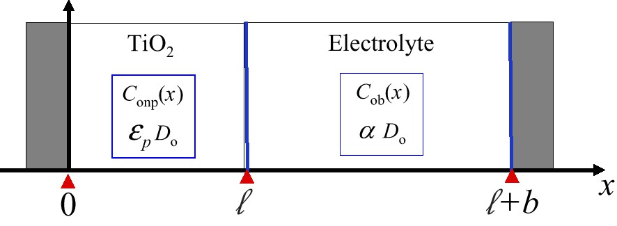
Schematic cross-sectional view of DSC.
List of symbols given in Fig. 1
| Cob(x) | Triiodide concentration in electrolyte at position x |
| Conp(x) | Triiodide concentration in TiO2 |
| C0(init) | Initial concentration of triiodide |
| Jlim | Short-circuit current density (lim: diffusion-limiting case) |
| D0 | Diffusion coefficient of triiode |
| εp | Porosity of TiO2 |
| α | Liquid electrolyte (LE) content in PSE |
| ℓ | TiO2 film thickness |
| b | Electrolyte layer thickness |
When the photon-limiting current flows, the concentration profiles of in a TiO2 nanopore region (Region I: 0 < x ≤ ) and in a bulk electrolyte region (Region II: < x < + b) are given below; is a TiO2 film thickness and b is a bulk electrolyte layer thickness.
Region I: 0 < x⩽ ≦
| (1) |
Region II: < X ≤ + b
| (2) |
| (3) |
Conp(x) and Cob(x) are concentrations at a position of x, respectively, in a TiO2 nanopore electrolyte and in a bulk electrolyte, and C0(init) an initial concentration of . εp is a porosity of TiO2. The equations become the ones given by Papageorgiou et al. [10] in the case of a liquid electrolyte, i.e. α = 1.
We calculated the concentration profiles of in the DSCs, employing three different sensitizing-dyes and two different cell-gaps. The two of the dyes are commonly used ones in DSCs, cis–bis(isothiocyanato)bis(2,2′-bipyridyl-4,4′-dicarboxylato)- ruthenium(II) bis-tetrabutylammonium (N719) and tris(isothiocyanato)-ruthenium(II)-2,2′:6′,2″-terpyridine-4,4′,4″-tricarboxylic acid, tris-tetrabutylammonium salt (black dye), and the third one is a hypothetical dye(920 nm-dye) with a sharp absorption edge at 920 nm, i.e. the optimal threshold for single junction solar cells [2]. The absorption spectra of the three dyes are given in Fig. 2. The maximum or photon-limiting photocurrent supposed to be achieved in the case of the photon-limiting for N-719, Black-dye, and 920 nm-dye are 16, 20.5, and 28 mA cm–2, respectively [2]. The concentration profiles between the electrodes are shown in Fig. 3. The concentration profiles of in DSCs with 50 μm cell-gap indicate that Jscs flow under diffusion-limiting conditions in all the cases since the concentration of at the Pt-counter electrode (x = 50 μm) can not be greater than zero as shown in Fig. 3. In contrast, the photocurrent of the DSCs with the cell-gap of 20 μm flows under photon-limiting conditions except for the PSE-based DSC formed with 920 nm dye.

Absorption spectra of three different dyes used for DSC. The maximum or photon-limiting photocurrent supposed to be achieved in case of the photon-limiting case for N-719, Black-dye, and 920 nm-dye are 16, 20.5, and 28 mA cm–2, respectively.

concentration profiles between the electrodes.
We now focus our attention on the minimum diffusion coefficient required to obtain the photon-limiting photocurrent. The photocurrent flowing under diffusion-limiting conditions is given in Eq. (4).
| (4) |
The minimum diffusion coefficients for the DSCs, tabulated in Table 2, are estimated by equating Jlim to Jph. The diffusion coefficient and/or I– of the DSC with a 50 μm cell-gap is required to be twice as high as the corresponding value of the 20 μm cell-gap DSC. Therefore, the cell-gap dependence shows clearly that narrowing the cell-gap is a simple, effective way to increase the Jsc.
Minimum diffusion coefficient of obtained on 12 different DSCs
| Cell gap µm | Dmin × 10–6 cm2 s–1 | |||||
| N719 (Iph = 16 mA cm–2) | Black-dye (Iph = 20.5 mA cm–2) | 92 nm-dye (Iph = 28 mA cm–2) | ||||
| solution | PSE | solution | PSE | solution | PSE | |
| 50 | 4.4 | 6.4 | 5.6 | 8.2 | 7.6 | 11.2 |
| 20 | 1.8 | 2.6 | 2.3 | 3.4 | 3.2 | 4.6 |
3.2 Equivalent circuit analysis of photocurrent in DSCs
In this section, the short-circuit current density of DSCs are discussed in terms of diffusion coefficients of and/or I–. Fig. 4 shows the current density–voltage (J–V) curves for DSCs with four different electrolyte solvents; MAN, MPN, GBL, and PC. As shown in Fig. 4, one of the characteristic features of the J–V curves is that the entire shape of a J–V curve is similar to each other irrespective of diffusion coefficients, but Jsc values decrease with decreasing the diffusion coefficient of and/or I–. The J–V characteristics of DSCs have been often discussed with an equivalent circuit depicted schematically in Fig. 5 by analogy with conventional p–n junction solar cells. The equation for the equivalent circuit is given by Eq. (5) [11].
| (5) |

Current–voltage curves of liquid-electrolyte-based and PSE-based DSCs.
MAN; methoxyacetonitril, MPN; 3-methoxypropionitril, GBL; γ-butyrolactone, and PC; propylene carbonate.

Equivalent circuit for DSC. Rs; series resistance, Rsh; shunt resistance.
Here J0 is the saturation current density, Rs the series resistance, Rsh the shunt resistance, q the electric charge, n the ideality factor, k the Boltzman constant, and T the temperature. J0 is mainly determined by the back electron transfer process from TiO2 to , and the Rs is composed chiefly of the resistance of a FTO thin film and a nanoporous TiO2 film, and ionic resistance of an electrolyte layer. The Rs is then given by Eq. (6) since the resistance of the electrolyte is assumed to change inversely proportional to the diffusion coefficient of and/or I– in the electrolyte.
| (6) |
In Fig. 6, the series resistance values of DSCs with four different electrolyte solvents are plotted with the reciprocal value of diffusion coefficient of and/or I–. Series resistance values were obtained from AC impedance spectra [8]. The experimental data (solid-squares) was fitted well with Eq. (6) (solid-line). The slope and the intercept at the axis of ordinate of the straight line give a and R0, respectively. Under short-circuit conditions, the relationship between the diffusion coefficients of and/or I– and short-circuit current density was derived into the form of Eq. (7): the third-term of Eq. (5) is neglected because Rsh is quite large.
| (7) |
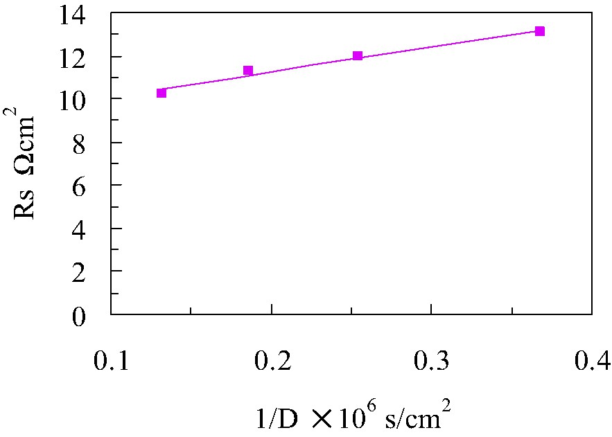
Series resistance values of DSCs with four different electrolyte solvents are plotted with the reciprocal value of diffusion coefficient of and/or I–.
Voc and Jsc are obtained from the J–V curves measured with various irradiation intensities. Voc values plotted with their respective Jsc on a semi-logarithm scale gives a straight line as shown in Fig. 7, from the slope of which the ideality factor was obtained to be about 1.8 for all the DSCs. Fig. 8 gives the Jsc dependence on the diffusion coefficient in liquid electrolyte-based DSCs and PSE-based DSCs. We fitted the experimental data with Eq. (7) using the known ideality factor of 1.8. The best-fitted curve shown as a solid-line in Fig. 8 was obtained when the J0 was adjusted to 1.06 × 10⁻⁴ A cm–2. This J0 value is five to six orders of magnitude larger than given in previous literatures [12–14]. A typical J0 value is in a range from 10–9 to 10–8 A cm–2, which was, however, confirmed to reproduce the experimental data with Eq. (7) far from satisfactory. We have been employing the fixed Jph of 16 mA cm–2 all the way through the discussion. In practice, the Jph value is found out to depend on the diffusion coefficient. Actually a similar Jph dependence on the ionic conductivity, or equivalently the diffusion coefficient, of polyacrylate derivative PSEs has been reported by Yanagida et al. [14]. We then focus on the back electron transfer from the nanoporous TiO2 to an oxidized dye, besides the back electron transfer to . This process is usually neglected because the reduction of the oxidized dye by I– is assumed to take place well before an electron in TiO2 reduces the oxidized dye. It is, however, pointed out that this process becomes not negligible in the case of a DSC with an electrolyte of low diffusion coefficient [12]. This is because I– may not diffuse in nanoporous TiO2 freely and part of oxidized dyes remains unchanged as it is without being reduced by I–.
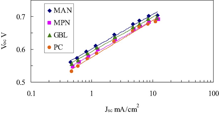
Relation between short-circuit current density and open circuit voltage.
MAN; methoxyacetonitril, MPN; 3-methoxypropionitril, GBL; γ-butyrolactone, and PC; propylene carbonate.
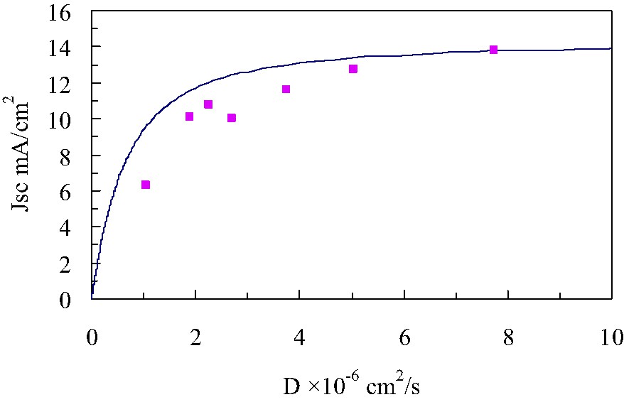
Short-circuit current density dependence on diffusion coefficient of liquid electrolyte-based and PSE-based DSCs. Experimental data; square, best-fitted curve; solid line. Jph = 16 × 10–3 A cm–2, n = 1.80, R0 = 8.93 Ω cm–2 q = 1.6 × 10⁻¹⁹ C, k T = 4.11 × 10⁻²¹ J, a = 1.16 × 10⁻⁵ Ω cm4 s–1. J0 = 1.06 × 10⁻⁴ A cm–2; this value is about three orders of magnitude greater than typical values reported in previous literatures.
A schematic diagram of the operating principle of a DSC under short-circuit conditions is given in Fig. 9. The operation process is composed of the following fundamental steps.
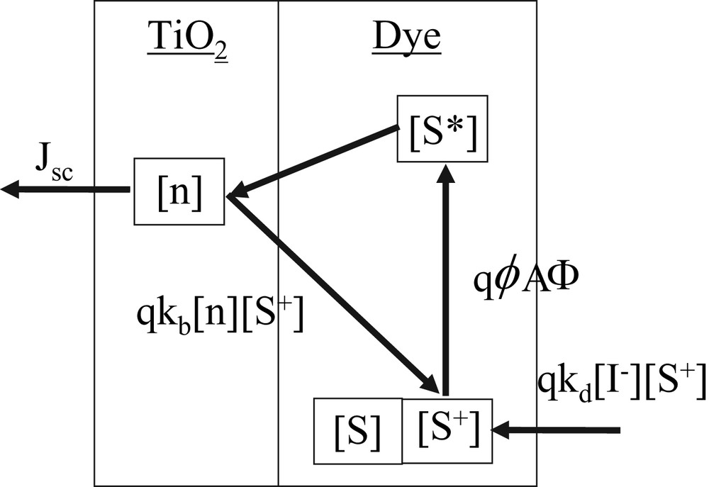
Schematic diagram of operating principle of DSC. kb and kd are the rate constants, respectively, for back and forward electron transfer reactions, [n] the electron density in TiO2, [S+] the oxidized dye concentration, ϕ the electron injection efficiency, Φ the incident photon flux, and A the ratio of absorbed photon flux to Φ.
Forward electron transfer process:
- • the dye absorbs the sunlight and an electron is photoexcited from a ground state to an excited state;
- • the electron is injected from the excited dye to a TiO2 conduction band, leaving behind an oxidized dye;
- • the electron is extracted through the TiO2 conduction band;
- • the oxidized dye is reduced by I–, returning back to its initial neutral state.
Backward electron transfer process:
- • part of the injected electrons in the TiO2 recombines with the oxidized dye.
Here, kb and kd are the rate constants, respectively, for back and forward electron transfer reactions, [n]: electron density in TiO2, [S+]: the oxidized dye concentration, ϕ: electron injection efficiency, Φ: incident photon flux, and A: the ratio of absorbed photon flux to Φ.
The series of equations for photo- and electrochemical kinetics in a DSC operating under steady state conditions is given below.
| (8) |
| (9) |
| (10) |
The electron concentration in the nanoporous TiO2 at a steady state equals summation of the initial concentration of electrons, [n0], at t = 0 and the concentration of steadily injected electrons from the excited dye. The balance equation is then
| (11) |
The short-circuit current density is derived from Eqs. (8)–(11) in the following form;
| (12) |
The equation is approximated to be
| (13) |
The Smoluchowski equation gives the relationship between kd and D, that is, kd = γ D λ [15]. Although γ was originally assigned to 4 π, γ given in the equation is a constant value less than 4 π because I– can only approach to S+ from a limited solid angle. With the Smoluchowski equation, Jsc is rewritten as a function of D:
| (14) |
The experimental data shown in Fig. 10 were fitted well with Eq. (14) by least-squares method. The fitting parameters thus obtained are as follows: [n0] = 1.96 × 1017 cm–3, γ = 2.35 × 10⁻², λ = 5.13 × 10⁻⁸ cm, kb = 2.74 × 10⁻¹² s–1. The first term on the right side of Eq. (5) becomes a leading term under short-circuit conditions because V = 0, and Jph in Eq. (5) should be replaced by Eq. (15) then;
| (15) |
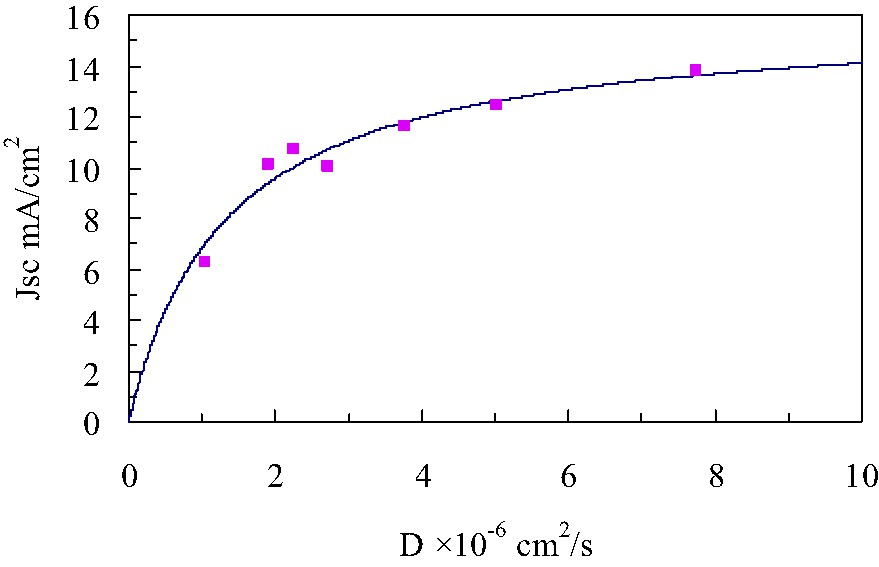
Short-circuit current density dependence on diffusion coefficient of liquid electrolyte-based and PSE-based DSCs. Experimental data; square, best-fitted curve; solid-line Jph = 16 × 10–3 A cm–2, λ = 5.13 × 10⁻⁸ cm, [I–] = 5.5 × 10⁻⁴ cm–3– kb = 2.74 × 10⁻¹² s–1, [n0] = 1.96 × 1017 cm–3, γ = 2.35 × 10⁻².
It is concluded that a back electron transfer from TiO2 to an oxidized dye also appear to influence on Jsc particularly when diffusion coefficient of and/or I– is low enough for an oxidized dye to be reduced before the back electron transfer reaction occurs [12].
The electron injection efficiency and incident photon flux are assumed to be constant all the way through the discussion because the electrolyte compositions used are essentially same in all the samples except for the matrix polymer and solvent.
4 Conclusion
We discussed photocurrent of DSCs with model equations of the two types of DSCs, choosing three different sensitizing-dyes; N719-, black-, and 920 nm-dyes. The Jsc is found out to increase even further by either increasing the diffusion coefficient of or decreasing the cell-gap, i.e. , or both. In particular, the cell-gap dependence indicates clearly that narrowing the cell-gap is a simple, effective way to increase the Jsc. The Jsc Jsc's of the DSCs studied here reach quite close to the Jph, if the cell-gap is reduced to 20 μm. The J–V characteristics of the DSCs were discussed by analogy with conventional p–n junction solar cells. We also discussed the diffusion coefficient dependence of Jsc. The back electron transfer from TiO2 to an oxidized dye was taken into account, which explained the diffusion coefficient dependence of Jsc well.