1 Introduction
Nitric oxide has drawn great attention due to its importance in biological systems [1–4]; the nitrosyl iron complex is the reaction product of nitric oxide and iron protein [5]. In order to facilitate the study of the bio-functions and reactivity between the NO and iron proteins, many biomimetic model compounds have been synthesized to resolve the relationship between function and electronic structure [6]. In this study, we focus on chemical bonding and electronic structure of two nitrosyl iron-thiolate complexes. The coordination sphere of Fe is in a tetragonal pyramidal Fe(NO)(S)4 geometry in both complexes, [(NO)Fe(S,S-C6H4)2] [PPN] (1) [6(c)], and Fe3(NO)3(S,S-C6H4)3 (2) [8(a)]. NO could be in a radical form NO•, a cation NO+, or an anion NO− form, which will in turn affect the electronic configuration of Fe. Based on the nomenclature introduced by Enemark and Feltham [7], the electronic structure of paramagnetic {Fe-NO}7 (St = 1/2, St = SNO + SFe) may have the following possible combinations between NO and Fe:
- • NO+ (SNO = 0) coupled to Fe(I) (d7, SFe = 1/2);
- • NO• (SNO = 1/2) coupled to Fe(II) (d6, SFe = 0);
- • NO−(SNO = 1) antiferromagnetically coupled to Fe(III) (d5, SFe = 3/2).
Furthermore, the non-innocent ligand [S2C6H4] in complex 1 and 2 makes it even more complicated to tell the exact electronic configuration on Fe or NO due to the possible formal oxidation states of –1 or –2 for such a thiolate ligand. Since different electronic configurations may be the consequence of their distinct reactivity, hence it is important to characterize the chemical bonding involved in order to establish the correct assignment of the electronic structure of each fragment of the molecule. Bond characterization is studied by a combination of experiment and theory; the molecular electron density may be provided by high resolution X-ray diffraction measurement, so as to be produced by the density functional theory (DFT) calculation. Topological analyses based on ‘atoms in molecule’ [9(b)] are followed to achieve the bond characterization.
Traditionally, the bond angles of Fe–N–O and IR spectroscopy are used to distinguish the possible states of NO [5–7]. If the M–N–O bond angle is ∼180° and the NO stretching frequency is 1600–1845 cm−1, it is assigned to be NO+; but if the bond angle is ∼120° and the ν(NO) is 1525–1720 cm−1, it is thought to be NO−. However, it is still hard to distinguish the NO+ or NO• simply by the bond angle and stretching frequency, where bond angles are around 159°∼178° and the NO stretching frequency is around 1695–1741 cm−1. Thus, the electronic configuration and electron density distribution of these compounds using X-ray absorption spectroscopy and single crystal X-ray diffraction may lead to useful insights in this respect.
The best way to elucidate the chemical bond experimentally is through the electron density distribution in terms of multipole model based on the precise measurements on the X-ray diffraction [9(a)]. The topological analyses of the total electron density will lead to the characterization of the chemical bonds [9(b)]. The atom specific character of X-ray absorption spectra of Fe and N/S would provide insight on the formal oxidation states of Fe, NO, and S-containing non-innocent ligands. The corresponding calculations based on DFT are undertaken in order to further understand the bonding.
2 Experimental
2.1 X-ray diffraction data and structural refinement
2.1.1 Data measurement for charge density analysis
Intensity data were measured on a Bruker Apex-CCD for complex 1 at 120 K. Data were collected on an Oxford Atlas-CCD for complex 2 at 100 K. All measurements were by Mo Kα radiation using 50 KV and 40 mA. The sample to detector distance was set at 50 and 55 mm for 1 and 2 respectively. In general, data were collected at fixed θ angle and with ω scan in different ϕ angles to be sure to satisfy the symmetry requirement. The data redundancy is at least 6. Data collection was made in three θ ranges: low, middle, and high angle ones. The overlap between the ranges was 10 degree in θ for the proper scaling of the data. The maximum 2θ angle is 90 and 120 degree for 1 and 2, respectively. Detailed crystal data is provided in the supporting information.
In order to suppress the saturation on the CCD detector, the strongest reflections, including the equivalent ones, were first located and the exposure time is determined to avoid the saturation of any pixel. In complex 1, the current is lowered instead to avoid exposure time being less than 5 s.
Integration on the intensity measurements were performed on SAINT and EVAL-14 programs [10(a)] for 1; and CrysAlisPro [10(b)] for 2. Different integration box sizes were used in low angle and high angle data to make sure the complete coverage of the peak intensity. Integrated intensities were then applied for absorption correction with the Gaussian integration method based on the face measurements. The exact same (h, k, l) reflections (not counting the symmetry equivalent reflections) in the overlap region are used to make the scaling between different settings of θ. A unique reflection is generated after merging the equivalent reflections. Structure refinements were followed using SHELX97 [10(c)] based on F2.
2.1.2 Multipole model refinement
The electron density is expressed in terms of the multipole model, each atomic electron density is modeled according to the equation [11(a)]:
The first two terms are the spherical part of the core and valence electron densities, respectively; Pc, Pv are population coefficients and κ, a radial expansion-contraction parameter. The third term is the non-spherical part of the density which is expressed as the sum of multipolar terms using the real part of spherical harmonic functions, . The population coefficients, , of multipole terms together with Pv, κ, κ’ are the parameters in the refinement using XD2006 [11(b)]. Up to hexadecapole is modeled for Fe, Cl, P and S; up to octupole for C, N and O; up to dipole for H are used. nl = 6, 6, 8, 8 is adopted for Fe, S, P; nl = 2,3,4 for C, N, O.
The internal coordinates of Fe are defined such that the z-axis is along the Fe-N direction, the x, y-axis is located in the perpendicular plane at the direction which bisects the angle ∠S–Fe–S direction as displayed in Fig. 1. The phenyl rings and P atoms of PPN+ are constrained to be the same respectively. No pseudo symmetry is applied to Fe and S atoms. The hydrogen positions were generated with C–H bond length of 1.08 Å. The atomic scattering factor of Fe is assumed to be [Ar]4 s23d6; where 4 s2 is not refined as valence electrons.
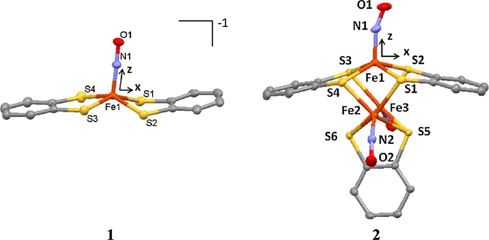
Molecular structures of 1 and 2.
2.2 X-ray absorption spectroscopy
X-ray absorption spectra were carried out at the National Synchrotron Radiation Research Center (NSRRC), Hsinchu, Taiwan. The Fe K-edge absorption spectrum was taken in transmission mode at 300 K at beamline BL-17 C using a Si(111) double crystal monochromator (DCM); the energy resolution ΔE/E is 2 × 10⁻⁴. High harmonics were removed by using Rh-coated mirrors. The spectra were obtained in the range 6.912 to 8.105 KeV using a gas-ionization detector. A piece of Fe foil is used as an internal standard for the calibration of energy. The S K-edge data were measured in fluorescence mode at BL-16A using Si(111) DCM; the energy resolution ΔE/E is 1.4 × 10⁻⁴. The spectrum obtained is from 2.4 to 3.0 KeV. The sample was ground from single crystal into powder before use. The photon energy is calibrated against the first pre-edge absorption of Na2S2O3 ·5H2O at 2472.02 eV. The spectrum of pure ligand, Na2S2C6H4, was taken for reference.
The spectra of Fe LII,III-edge and N K-edge absorption were obtained at BL-20A with slit of 10 × 10 μm which corresponds to ∼ 0.08 eV and ∼0.15 eV energy resolution for the N K-edge and Fe LII,III-edge, respectively. Samples were prepared as mentioned above and loaded into a vacuum chamber (10−9 torr). The spectra were taken in total electron yield mode. Energy was calibrated against Fe LIII edge absorption at 708.5 eV of α-Fe2O3 and oxygen at 531.3 eV of Cr oxides absorption.
2.3 Computation
2.3.1 Density functional theory (DFT) calculation
DFT calculations were carried out by the Amsterdam Density Functional (ADF) version 2010.01 [12], and ORCA version 2.8 [13(a)]. The SCALAR ZORA was applied for relativistic corrections. The molecular geometry was taken from the single crystal structure. The geometry optimizations was performed by BP86 [14] exchange functional and triple-ζ Slater type with additional two polarization functions (TZ2P) basis set in the ADF program. Based on the pre-edge fitting of S K-edge spectra, a spectroscopy corrected DFT was used to seek a better exchange functional for both complexes 1 and 1R. The electronic structure calculations were carried at PBE0 [15] exchange functional with (20% HFx mixing) and def2-TZVP(-f) basis set in the ORCA program. The mixing of 20% HF exchange part is chosen to reproduce the pre-edge peak of S K-edge spectra. The different ratios in HFx mixing based on B3LYP functional were also examined, but failed to match the pre-edge energy and the peak intensity of the S K-edge absorption. As a matter of fact, the best choice of complex 1 is BLYP. Here the choice of PBE0 functional is a compromise for both 1 and 1R. The topological properties based on the calculated electron density are analyzed using AIMALL program [11(b)].
2.3.2 Delocalization index
For a given basin, it can be divided into two parts, one is localization region, λ(A), and the other is delocalization region, δ(A,B). Thus the atomic population of atom A can be expressed as the following formula [16]:
Here Sij stands for the overlap integral. The bond order and delocalization index are strongly correlated, because the latter form provides a measure of the Fermi correlation shared between atomic basins and hence of the number of electrons shared. Matta and Hernandez-Trujillo [16(c)] suggested using such a delocalization index to replace the bond order, which could correlate with ρb and Hb. The index is defined as:
Such a derivation is better than the old one (the equation of bond order and ρb) since the magnitude of the bond order is always arbitrarily assigned.
3 Results and discussions
3.1 Structures and multipole model
The crystal structures of both 1 and 2 at 300 K were reported previously [6(c),8(a)]. The structure at 100 K is basically the same as that at 300 K for both complexes. The least squares refinements were processed with a spherical model and then a multipole model. Significant improvement on the agreement indices of the multipole model against the spherical one is apparent shown in Table 1; this means that the multipole model does give a better representation of the electron density than the spherical one does. The total electron density is then produced according to this multipole model. The subsequent topological analyses are all based on this total electron density. The coordination geometry around Fe in all the complexes is square-pyramidal with four S-atoms at equatorial plane and NO at the axial position. The molecular structure and the local coordinates of Fe of 1 and 2 are shown in Fig. 1.
Agreement indices of multipole refinements on complex 1 and 2.
| Complex/Nref | Spherical | Monopole | Octapole | Hexadecapole | +κ’ |
| 1/18014 | |||||
| Nvar | 550 | 592 | 1069 | 1140 | 564 |
| R(F2) | 0.0588 | 0.0526 | 0.0377 | 0.0373 | 0.0358 |
| Rw(F2) | 0.0683 | 0.0605 | 0.0449 | 0.0444 | 0.0429 |
| GOF | 1.4941 | 1.3231 | 0.9967 | 0.9885 | 0.9556 |
| 2/23335 | |||||
| Nvar | 310 | 149 | 681 | 761 | 110 |
| R(F2) | 0.0302 | 0.0263 | 0.0228 | 0.0186 | 0.0173 |
| Rw(F2) | 0.0370 | 0.0325 | 0.0258 | 0.0212 | 0.0197 |
| GOF | 3.2716 | 2.8756 | 2.2912 | 1.8966 | 1.7617 |
3.2 Laplacian density distribution
In addition to the agreement indices, the correctness of the model can be evidenced by the featureless in residual density maps, where the electron density is the differences in density between the measurement and the multipole model, (ρobs.–ρmultipole). Typical residual maps of the ligand and area around Fe of 2 are shown in Fig. 2a and c, where the corresponding deformation density is depicted in Fig. 2b and d, respectively. All the bonding effects and the asphericity in electron density around Fe are quite obvious, the residual density are essentially featureless within 3σ.
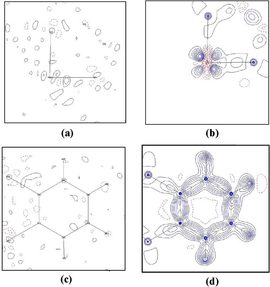
Residual (a, c) and deformation density (b, d) maps at the plane of (a), (b) the S1–Fe1–S2 plane; (c, d) the benzene plane of complexes 2, calculated using the full data (sinθ/λ ∼ 1.1 Å−1); contour interval ±0.1 e/Å3; solid lines positive and dash lines negative.
Laplacian maps of complexes 1 and 2 both from experiment and from theory are displayed in Fig. 3. The agreement between experiment and theory is very good. One can easily observe that each C atom of the benzene ring has three local charge concentrations (LCC) on its valence shell around the nucleus at the benzene plane, which is in accord with an sp2-type in its valence shell; one of the LCC is toward the H forming C–H covalent bond, the other two LCCs are toward the bonded C forming C–C bonds, and thus the typical share interaction or covalent bond is characterized with two LCCs facing directly to each other. There are four LCCs around each S atom in its valence shell, roughly in tetrahedral geometry; one is toward C forming a C–S bond, one is toward Fe forming a coordinated bond, and the other two are located at the plane perpendicular to S–Fe–S, which represent two lone pair electrons. The valence shell charge concentration (VSCC) of Fe at the S–Fe–S plane of 1 and 2 shown in Fig. 3 is apparently in its 3d quantum shell and appears quite similar to those of other 3d-metal complexes [17–19]; i.e. the LCC is found at the dπ direction (bisecting of angles∠S–Fe–S) and local charge depletion (LCD) is located at the dσ direction (along Fe–S). However, such a feature is not so pronounced as those of other metal complexes [17–19]. The Laplacian distribution at the plane of Fe(1)–Fe(2)–Fe(3) of 2 shown in Fig. 3(e) and (f) demonstrate the σ-donor character of the N atom. The N–O bond of NO+ is expected to be covalent, a strong share interaction, more so than that of the C–C bond in a benzene ring. However, it is not so in Fig. 3(e); nevertheless, the topological properties associated with bond critical point (BCP) of N–O listed in Table 2 still indicate a strong shared interaction with ρc and Hb value of 3.5 eÅ−3 and − 6.9 HÅ−3 respectively; in addition, the delocalization index of N–O is close to 2.
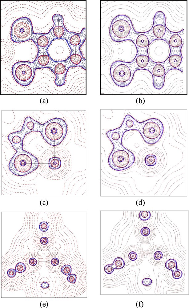
Laplacian maps of (a) the plane of dithio-phenyl ring (S2C6H4) of 1; (c) the plane of Fe(1)–S(1)–S(2) in 2; (e) the plane of Fe(1)–Fe(2)–Fe(3) in 2. (a, c, e) are from experiment; (b, d, f) are the corresponding ones from DFT calculation. Contours are drawn as ±2i × 10j, i = 1–3, and j = −2 ∼ 2. Solid lines positive and dashed lines negative.
Topological properties associated with bond critical point (BCP) of 1 and 2: comparison between experiment (1st row) and density functional theory (DFT) calculation (2nd row).
| Complex | Bond type | BL (Å) | d1 (Å) | ρc (e/Å3) | ▿2ρc (e/Å5) | Hb (H/Å3) |
| [Fe(NO)(S2C6H4)2]−1 | Fe1–S1 | 2.2451(3) | 1.12 | 0.67 | 4.32 | −0.31 |
| (1) | 1.03 | 0.60 | 3.44 | −0.21 | ||
| Fe1–S4 | 2.2096(3) | 1.11 | 0.64 | 5.96 | −0.24 | |
| 1.03 | 0.61 | 3.55 | −0.21 | |||
| Fe3(NO)3(S2C6H4)3 | Fe1–S1 | 2.2637(2) | 1.04 | 0.65 | 3.00 | −0.32 |
| (2) | 1.04 | 0.56 | 4.25 | −0.19 | ||
| Fe1–S2 | 2.2665(2) | 1.04 | 0.54 | 3.46 | −0.21 | |
| 1.04 | 0.56 | 4.16 | −0.19 | |||
| Fe2–S1 | 2.3220(2) | 1.07 | 0.44 | 3.30 | −0.12 | |
| 1.07 | 0.50 | 3.50 | −0.15 | |||
| Fe2–S5 | 2.2577(2) | 1.04 | 0.55 | 3.66 | −0.21 | |
| 1.04 | 0.57 | 4.12 | −0.19 | |||
| (1) | Fe1–N1 | 1.6131(9) | 0.85 | 1.52 | 27.91 | −0.96 |
| 0.80 | 1.50 | 31.31 | −0.77 | |||
| (2) | Fe1–N1 | 1.6900(6) | 0.87 | 1.35 | 19.48 | −0.81 |
| 0.87 | 1.19 | 22.17 | −0.52 | |||
| Fe2–N2 | 1.6622(6) | 0.87 | 1.45 | 21.03 | −1.00 | |
| 0.86 | 1.23 | 27.08 | −0.53 | |||
| (1) | N1–O1 | 1.176(3) | 0.51 | 3.28 | 25.07 | −5.23 |
| 0.53 | 3.71 | −36.23 | −5.50 | |||
| (2) | N1–O1 | 1.1685(9) | 0.52 | 3.33 | 4.50 | −5.87 |
| 0.52 | 3.65 | −35.58 | −5.40 | |||
| N2–O2 | 1.1623(7) | 0.50 | 3.59 | −8.73 | −6.97 | |
| 0.50 | 3.78 | −39.52 | −5.85 |
One of the main targets of this study is to be able to tell the differences between NO+, NO• and NO− in the complexes. The Laplacian maps based on the DFT calculations for these three species are depicted in Fig. 4. There are two lone pairs located at the O atom with an angle of ∼30 degree from the N–O line for NO−, but only one lone pair along the N–O line for NO+; while in the case of NO radical, less charge concentration than NO+ is observed at the bond and lone pair region since the singly occupied MO (SOMO) is at π* anti-bonding orbital. One can predict when the transition metal is bonded to the NO+ ligand; the metal to ligand charge transfer would make the π* orbital of NO+ be populated, hence decreasing the bond order of NO+ and making it look like NO radical. Thus it will be difficult to tell the difference of NO+ and NO radical based on the electron density along Fe–N–O. However, in the cases of 1 and 2, the electron density distribution of N–O shown in Fig. 3(f) does appear to be close to the NO radical of the free molecule (Fig. 4).
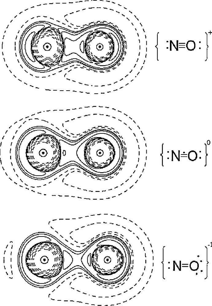
Laplacian maps of NO in NO+; NO radical and NO−. Contours are ±2i × 10j e/Å5, where i = 1–3 and j = −1−1; others defined as in Fig. 3.
3.3 Topological properties
The topological properties associated with BCPs both from experiment and DFT calculation for Fe–S, Fe–N and N–O bond of 1 and 2 are listed in Table 2; those from DFT calculations of the related compounds are given in Table 3. The bond characters of Fe–S and Fe–N(O) are similar to those of related complexes; with positive values in ▿2ρc, but negative values in Hb; ρc value of 0.5, 1.5 eÅ−3 and Hb value of − 0.2, − 0.6 for Fe–S and Fe–N, respectively. Fe–S is typical for M–L bonds [17,19], which can be defined as recipient [19(c)] or polarized covalent bond. Based on the ρc and Hb values, Fe–N(O) bonds are definitely stronger bonds than those of metal-amide or metal-pyridal M–N bonds with bond length ∼ 2.0 Å with typical ρc, and Hb value of 0.5 ∼0.7 e/Å3 and − 0.05 ∼ − 0.1 Hartree/Å3 [18]; it is also stronger than that of Ni-Nimide in Ni(s-disn)2 and Ni(S2C2(CF3)2)(s-disn) where the ρc value is 0.8 ∼ 0.9 e/Å3 with bond length of 1.83 ∼ 1.87 Å and with Hb value –0.2 Hartree/Å3 [17(b)]. Therefore, the Fe–N(O) bond does appear to have a double bond character, which is consistent with the delocalization index being 1.4∼1.6. In order to see whether the possible π-character exists in the Fe–N(O) bond, a Fermi-hole (FH) function is investigated; the FH distribution of Fe–N–O depicted in Fig. 5 clearly indicate that the existence of share interaction between Fe and N/S atoms, similar findings were found in many metal-ligand coordinated bond in 3d-metal complexes[17–19]; discussions on such coordinated or dative bonds were reported extensively [17–19]; the FH at the Fe–N–O π-plane with the reference electron located at 0.53 Å away from N atom is shown in Fig. 5 (c) and it clearly indicates the d-π* (NO)character of Fe–N π bond; such M–L π interactions through FH distribution was also observed for Cr–Nnitrido; Cr–Ooxo bond, where a triple bond is realized with 1σ and 2π bonds [18]. The bond length of Fe–N(O) is somewhat longer (1.61 ∼ 1.69 Å) than that of Cr–Nnitrido (1.56 Å); the ρc and absolute Hb values (∼1.5 e/Å3; − 0.66 Hartree/Å3) are less than those of Cr–Nnitrido (1.87 e/Å3; − 1.7 Hartree/Å3) but much higher than those of M–Npy or M–Nimide [18]. The Fe–N(O) bond is definitely a covalent character with bond order more than one but less than 3; this is also indicated by delocalization index of 1.4∼1.6.
Topological properties associated with bond critical point (BCP) of Fe–S; Fe–N Fe–Fe and N–O bonds from density functional theory (DFT) calculations.
| Complex | Bond type | BLa (Å) | d1 (Å) | ρc (e/Å3) | ▿2ρc (e/Å5) | Hb (H/Å3) | δ(A,B) |
| Fe(NO)(S2CNEt2)2 | Fe1–S1 | 2.291(2) | 1.05 | 0.53 | 3.74 | −0.17 | 0.69 |
| Fe1–S4 | 2.261(3) | 1.04 | 0.56 | 3.93 | −0.19 | 0.71 | |
| [Fe(NO)(S2C6H4)2]−1 (1) | Fe1–S1 | 2.2451(3) | 1.03 | 0.60 | 3.44 | −0.21 | 0.86 |
| [Fe(NO)(S2C6H4)2]−2 (1R) | Fe1–S1 | 2.252 | 1.03 | 0.57 | 4.07 | −0.19 | 0.77 |
| Fe1–S4 | 2.313 | 1.03 | 0.50 | 3.69 | −0.15 | 0.70 | |
| Fe3(NO)3(S2C6H4)3 (2) | Fe1–S1 | 2.2637(2) | 1.04 | 0.56 | 4.25 | −0.19 | 0.72 |
| Fe2–S1 | 2.3220(2) | 1.07 | 0.50 | 3.50 | −0.15 | 0.66 | |
| Fe3(NO)3(S2C6H4)3[PF6] | Fe1–S1 | 2.224(2) | 1.02 | 0.60 | 4.00 | −0.21 | 0.78 |
| (2O) | Fe1–S2 | 2.236(2) | 1.03 | 0.61 | 4.40 | −0.22 | 0.78 |
| Fe2–S5 | 2.260(2) | 1.04 | 0.57 | 3.92 | −0.20 | 0.75 | |
| Fe2–S1 | 2.311(2) | 1.06 | 0.51 | 3.52 | −0.16 | 0.69 | |
| (2) | Fe2–Fe3 | 2.5768(1) | 1.27 | 0.31 | 0.55 | −0.11 | 0.34 |
| (2O) | Fe1–Fe2 | 2.672(1) | 1.34 | 0.26 | 0.98 | −0.07 | 0.27 |
| Fe2–Fe3 | 2.569(2) | 1.29 | 0.32 | 0.53 | −0.11 | 0.37 | |
| Fe(NO)(S2CNEt2)2 | Fe–N | 1.65(1) | 0.86 | 1.28 | 28.92 | −0.58 | 1.45 |
| (1) | Fe1–N1 | 1.6131(9) | 0.80 | 1.50 | 31.31 | −0.77 | 1.68 |
| (1R) | Fe1–N1 | 1.660 | 0.89 | 1.32 | 22.15 | −0.64 | 1.40 |
| (2) | Fe1–N1 | 1.6900(6) | 0.87 | 1.19 | 22.17 | −0.52 | 1.37 |
| Fe2–N2 | 1.6622(6) | 0.86 | 1.23 | 27.08 | −0.53 | 1.41 | |
| (2O) | Fe1–N1 | 1.646(8) | 0.85 | 1.30 | 28.25 | −0.57 | 1.53 |
| Fe2–N2 | 1.648(6) | 0.85 | 1.29 | 28.66 | −0.57 | 1.53 | |
| Fe(NO)(S2CNEt2)2 | N–O | 1.14(1) | 0.48 | 4.15 | −51.99 | −7.26 | 1.98 |
| (1) | N1–O1 | 1.176(3) | 0.53 | 3.71 | −36.23 | −5.50 | 1.87 |
| (1R) | N1–O1 | 1.189 | 0.53 | 3.60 | −35.40 | −5.30 | 1.90 |
| (2) | N1–O1 | 1.1685(9) | 0.52 | 3.65 | −35.58 | −5.40 | 1.98 |
| N2–O2 | 1.1623(7) | 0.50 | 3.78 | −39.52 | −5.85 | 1.97 | |
| (2O) | N1–O1 | 1.159(10) | 0.51 | 3.93 | −42.42 | −6.26 | 1.99 |
| N2–O2 | 1.150(7) | 0.50 | 4.02 | −45.49 | −6.59 | 1.98 |
a BL with parentheses means the bond length based on those from experiment.
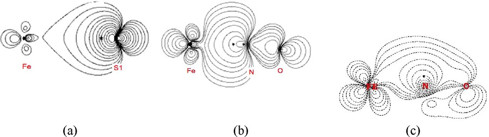
Fermi hole functions of (a) Fe–S with the reference electron (*) at 0.72 au from S(1) atom toward Fe; (b) Fe–N–O with * at 0.63 au from N(1) toward Fe; (c) the plane perpendicular to (b) with * at 1.0 au from N(1) showing the d-p π character of Fe–N(1)–O(1). Contour interval 2i × 10j (i = 0 ∼2; j = −3, ∼0).
In order to tell the exact electron configuration of the NO group in these complexes, additional unrestricted DFT calculations were performed on NO molecules with different electronic configurations in the gaseous state. The topological properties associated with the BCP of the N–O bond based on such calculations are given in Table 4. According to the high values of ρc and negative Hb, the N–O bond is definitely a covalent bond with bond order much greater than a single bond. According to the calculated topological properties associated with BCP in 1 and in 1R, the average ρc, and |Hb| values of Fe–N bond in 1 is larger than those of 1R (1.50 vs 1.32eÅ−3), but values of Fe–S and N–O bonds are nearly the same. Since 1R is a one electron reduction product from 1, this implies that the additional electron is populated on a molecular orbital which is anti-bonding character in Fe–N, and this is realized by the analysis of MO coefficients from DFT calculation. As a matter of fact, the SOMO orbital (Fig. 11b, 94α) of 1R is indeed an anti-bonding in Fe–N, but a non-bonding in Fe–S and a σ-bonding of N–O. The bonding characters will be further discussed by X-ray absorption spectroscopy and MO coefficients in the DFT calculation.
Topological properties associated with bond critical point (BCP) in various NO states based on calculation.
| State/bond Length (Å) | d1 (Å) | ρc (e/Å3) | ▿2ρc (e/Å5) | Hb (hartree/Å3) |
| NO+/1.0712 | 0.42 | 5.06 | −74.84 | −11.40 |
| NO•/1.1595 | 0.49 | 3.93 | −44.40 | −6.76 |
| NO−/1.2875 | 0.58 | 2.79 | −19.23 | −3.37 |
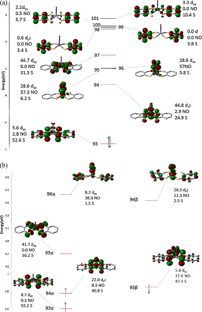
The Frontier MOs of (a) 1 and (b) 1R. Numbers shown are the percentage of Fe d, NO 2p and S 3p orbitals in each MO.
In the tri-iron complex 2 and 2O, Fe–S and Fe–N bonds are similar in the topological properties. The electron density distribution around each Fe is very similar. However, a BCP is found between Fe2 and Fe3 in the MO calculation, but not in the experimental data. The topological properties associated with BCP of N–O bonds also indicate that it is slightly stronger in 2O than in 2, but with the delocalization indices unchanged.
In comparison of 1 and 2, the Fe–S bond for both compounds is roughly the same; however the Fe–N bond does show difference with that of 1 much stronger than that of 2 (ρc of 1.50 vs 1.19 eÅ−3); this means the bond order of Fe–N in 1 is larger than in 2, which is consistent with the delocalization index, δ(A,B), 1.68 vs 1.37 listed in Table 3. In other words, the Fe–Fe interaction in 2 would weaken the Fe–N bond.
According to the topological properties associated with the BCP of the N–O bond in all complexes, the N–O bond is certainly of covalent character with multiple bonding; the bond order is close to three, though it is very similar to those of NO• based on the values given in Table 4. Delocalization index, δ(A,B), of Fe–N bonds are greater than 1.0, which implies some back-bonding characters from Fe to NO π*; the δ(A,B) of N–O bonds are almost the same in 1 and 1R. The delocalization index of Fe–N and N–O bonds is 1.68 and 1.87 respectively for 1, and is 1.40 and 1.90 for 1R. The hybridization of nitrogen atom in 1 can be recognized as a sp hybrid, and Fe–N–O is nearly linear. However, in 1R, the index of Fe–N is smaller (1.40) than that of 1, which means the decrease in double bond character of Fe–N, so that the bond angle of ∠Fe–N–O becomes less than 180°.
d-orbital populations of Fe in 1 and 2 can be obtained from the multipole model; they are listed in Table 5. All the Fe ions are in square pyramidal geometry where dz2 and dxy orbitals are in the σ direction, but where the other three are in π direction. Generally, it indicates that higher populations are found in dπ than in dσ, which is in accord with the prediction of crystal field theory.
d–Orbital populations of Fe in complex 1 and 2.
| 1 | 2 | ||
| Fe | Fe1 | Fe2 | |
| dz2 | 1.00 | 1.20 | 1.23 |
| dxy | 1.57 | 0.84 | 0.79 |
| dxz | 1.35 | 1.36 | 1.25 |
| dyz | 1.48 | 1.13 | 1.23 |
| dx2–y2 | 1.63 | 1.59 | 1.64 |
| total | 7.03 | 6.12 | 6.14 |
The fragment charge of iron nitrosyl complexes are listed in Table 6. It indicates that no significant change is found in the charge of Fe, yet the extra negative charge in these compounds is distributed among NO and the thiolate ligands. One can see the additional negative charge of 1R vs 1 is mainly distributed in thiolate, which increases ∼0.4 on each thiolate ligand, but ∼0.2 on NO. In comparison of 2 and 2O, the additional charge in 2 is evenly distributed among thiolate (∼0.2) and NO (∼0.15) ligands.
Fragment charge of Fe(NO)(S2CNEt2)2, complex 1, 1R, 2 and 2O.
| Fe | NO | S-ligand | |
| Fe(NO)(S2CNEt2)2 | 0.962 | −0.337 | −0.310/−0.314 |
| [Fe(NO)(S2C6H4)2]−1 (1) | 0.936 | −0.287 | −0.820/−0.828 |
| [Fe(NO)(S2C6H4)2]−2 (1R) | 0.995 | −0.510 | −1.234/−1.248 |
| Fe3(NO)3(S2C6H4)3 (2) | 0.891 | −0.339 | −0.599 |
| 0.856 | −0.299 | −0.562 | |
| 0.858 | −0.325 | −0.485 | |
| Fe3(NO)3(S2C6H4)3 | 0.802 | −0.141 | −0.326 |
| [PF6] | 0.780 | −0.159 | −0.282 |
| (2O) | 0.779 | −0.159 | −0.286 |
3.4 X-ray absorption spectroscopy
3.4.1 Fe K-edge absorption spectroscopy
XANES of the Fe K-edge are shown in Fig. 6. The local environment of Fe in (NO)Fe(S2CNEt2)2 is described as a five coordination in a pseudo square pyramidal geometry. Therefore (NO)Fe(S2CNEt2)2, 1 and 1R all have the same local geometry around Fe. The apparent pre-edge peak of Fe K edge absorption shown in Fig. 6 is due to the symmetry allowed 1 s to 3d transition. The formal oxidation state of Fe in 1 and 1R are definitely higher than that of Fe-foil; but lower than those of FeO and Fe2O3. In addition, the average oxidation state of Fe in 1 and 1R should be the same as that in (NO)Fe(S2CNEt2)2, which is known as a nitrosyl ligand (NO+) bonded to a low spin d7 Fe(I) [20]; thus the Fe in 1 is likely to be Fe(I), but Fe in 1R is best described as the combination of Fe(I)/NO+ and Fe(II)/NO radical. The difference in edge absorption between 1 and 1R is ∼ 0.6 eV.
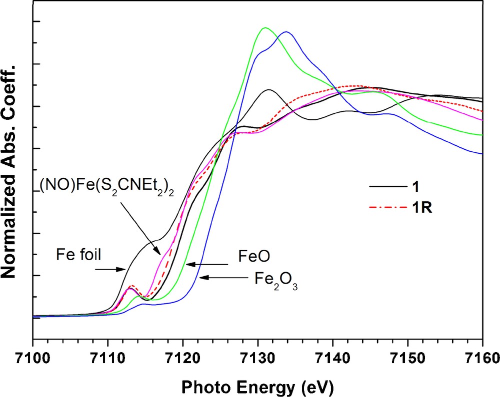
Fe K-edge spectra of complex 1, 1R and related iron compounds.
3.4.2 Fe LIII,II-edge absorption spectroscopy
The Fe LIII,II-edge spectra are displayed in Fig. 7 as the 2p→3d transition, which should be very sensitive to d-orbital populations, hence the electronic configuration of Fe. The LIII absorptions are around ∼707.1 eV and ∼708.2 eV for these three complexes. The electronic configuration of these Fe complexes should have the same formal oxidation state, that is d7 of Fe(I). The difference between 1 and 1R is only 0.4 eV; hence the one electron reduction from 1 to 1R may play little effect on Fe.
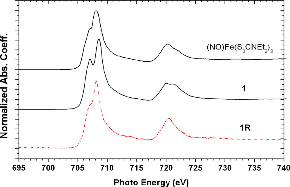
Fe L3,2-edge spectra of complex (NO)Fe(S2CNEt2)2, 1, and 1R.
3.4.3 S K-edge absorption spectroscopy
In order to be sure on the assignment of formal oxidation states of each component of the complexes, the S K-edge absorption spectra of complexes 1 and 1R are studied and they are displayed in Fig. 8. In transition-metal complexes containing one or more unoccupied d-manifold; the S K-edge is featured by an intense pre-edge absorption corresponding to a S1s→ψ* transition, where ψ*is an unoccupied or partial occupied M-S orbital. The intensity (D0) of such pre-edge transition is given as [21]:
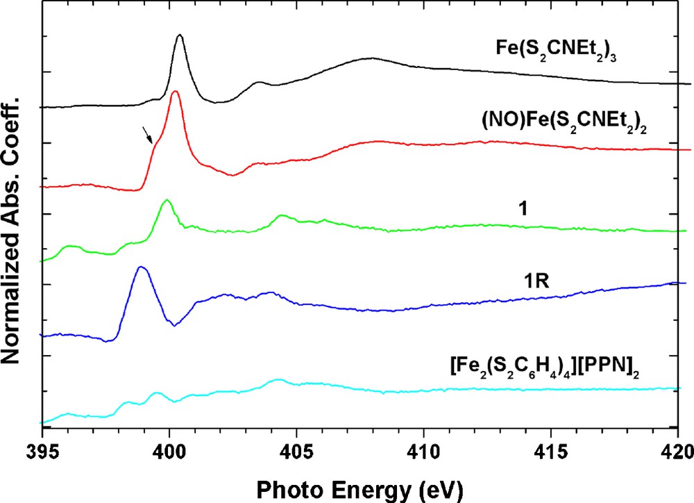
N K-edge spectra of all nitrosyl iron complexes. The arrow indicates the NO contribution on Fe(S2CNEt2)2.
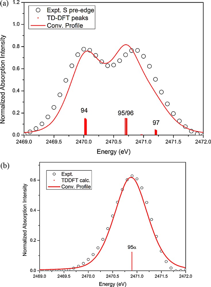
The experimental (open circle) and TD-DFT calculated (red solid line) pre-edge S K-edge absorption of (a) 1 and (b) 1R.
3.4.4 N K-edge absorption spectroscopy
In order to characterize the NO ligand in these complexes, the N K-edge absorption spectra of all these complexes are investigated and displayed in Fig. 9. Taking NO ligand in (NO)Fe(S2CNEt2)2 complex as a nitrosyl form, NO+, bonded to a Fe(I) [20], the N K-edge absorption of complexes Fe(S2CNEt2)3 and [Fe(S2C6H4)]2[PPN]2 are taken as references for the ligand S2CNEt2 and the [PPN] cation. The strongest peak around the 399∼400 eV is assigned to be the transition of 1s→π*, the 1s→σ* should be around the 413 eV. The transition around 404∼405 eV is contributed from the cation [PPN]+ shown at the bottom of Fig. 8. One can obtain a 1s→π* transition energy of NO+ around 399.6 eV and 399.9 eV for (NO)Fe(S2CNEt2)2 and 1 respectively; with peak width of 0.8 eV in 1. It is obvious that the reduced form 1R has much lower energy and broader peak for this 1s→π* transition; which can be deconvoluted into two transitions at 398.7 and 399.3 eV with FWHM = 0.9 eV. According to the MO calculation of free ligand NO in the form of NO+, NO radical and NO−, only the NO radical may exhibit two 1s→π* transition peaks (398.96 eV; 399.66 eV); the other two species have only one transition peak at 402.05 and 397.91 eV for NO+ and NO−, respectively. When the ground state of NO radical is (1sσNα)1(1sσNβ)1(π*α)1, the allowed 1s→π* transitions may have two possibilities; (1sσNα)1(1sσNβ)0(-π*α)1(π*β)1 and (1sσNα)0(1sσNβ)1(π*α)2. But in the case of NO+ or NO−, there is only one configuration. Based on the number of peaks in 1s→π* transition, the NO ligand in complex 1R is likely to be in a radial state; and complex 1 is in the NO+ state. In complexes 2 and 2O, both have only one absorption peak ∼401 eV which fits to be NO+ state for each NO group.
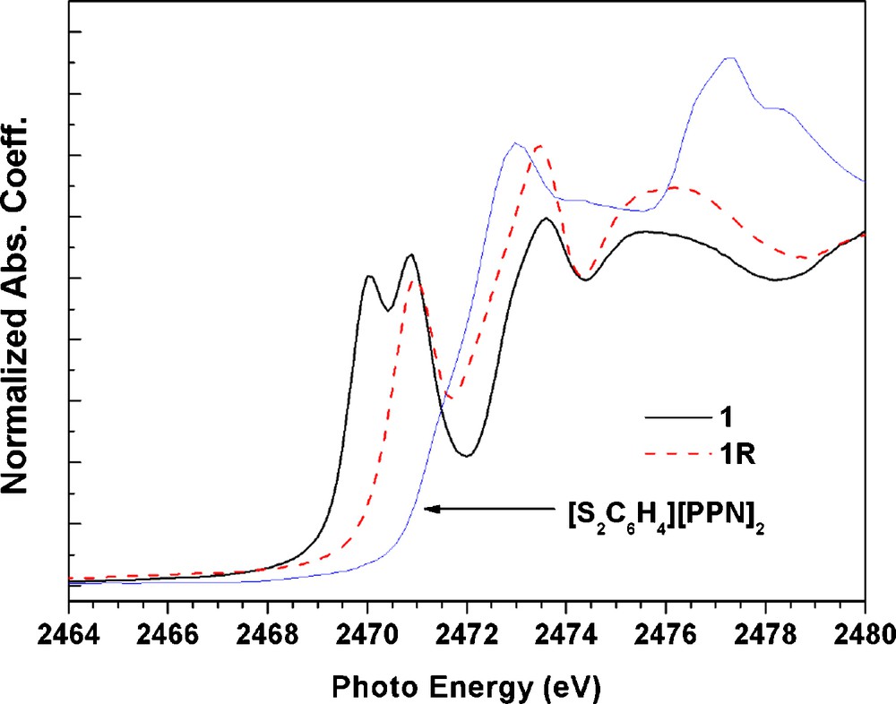
The S K-edge absorption spectra of complex 1; 1R and (S2C6H4)2−.
Based on the XAS at Fe, N and S elements, the one electron reduction from 1 to 1R causes significant change in N and S K-edge absorption spectra which indicate that the reduction is mainly taking place at the ligands NO and thiolate. This is consistent with the fragment charges listed in Table 6, where the difference is ∼0.2 and ∼0.8 e for ligand NO and di-thiolate respectively.
3.5 Electronic configuration of complex 1 and 1R
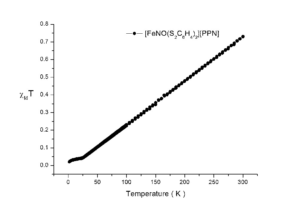
The χMT value of 1 decreases from 0.73 to ∼0.02 cm3mol−1K when the temperature decreases from 300 to 2 K (supplementary figure); which corresponds to a strongly antiferromagnetic coupling between two unpaired electrons: in this case, one unpaired electron is located in one of the dithiolate ligands; the other unpaired electron is located in {FeNO}7 group. The additional electron in 1R is believed to be populated on the SOMO orbital (94α in Fig. 11b) of Fe(dz2)/S(pz)/NO(σ), which exhibits paramagnetic behavior of one unpaired electron. The radical character of NO is evidenced on the shoulder peak of N K-edge; the Fe K- and L- edge absorptions do show a little shift from 1 to 1R; in other words, the unpaired electron in 1R is delocalized along Fe–N–O.
To gain more insight into the spectra, the corresponding TD-DFT calculation results in the pre-edge absorption region are displayed in Fig. 10. The first absorption peak of 1 at ∼2470 eV is related to the transition of 1s(S) to LUMO (94 of Fig. 11a), the second peak at ∼2470.9 eV is assigned as the transition to orbital 95/96 and 97. According to the MO diagram depicted in Fig. 11(a), the first peak corresponds to the transition to an unoccupied orbital mainly by the mixing of Fe(3dz2)/S(3pz), a non-bonding of Fe–S; the second one is the Fe(3dxy)/S(3px, py) mixing state, which is the σ*Fe−S antibonding orbitals. The number shown next to each MO is the Löwdin population [22] in percentage of each component. The population ratio of S(3pz) to S(3px, py) in these unoccupied states is ∼1: 1.6, which implies the formal charge of two dithiolate ligands can be assigned as − 1 and − 2, just as those of [Ni(S2C2Me2)]1− [21(a)]. Furthermore, two nearly degenerate MO of 95 and 96 are mainly contributed from π* of NO+. The MO diagram of complex 1R is displayed in Fig. 11(b). The one electron reduction of complex 1 takes place at the SOMO (94α), which is the mixing of Fe(3dz2) and S(3pz), on the contrary, the unoccupied 94β is predominately the mixing of Fe(3dz2) and NO nearly no contribution from S(3pz). Take a closer look at the LUMO (94 in Fig. 11(a)) of 1, which consists ∼45% of Fe(3dz2), ∼25% of S(3pz), but very little contribution from NO. However, the SOMO (94α in Fig. 11(b)) of 1R consists ∼ 41% of S(3pz), ∼22% of Fe(3dz2), and ∼8% of NO. Interestingly, the unoccupied orbital 94β consists ∼26% of Fe(3dz2) and ∼11% of NO(π*), no contribution from the thiolate ligand.
4 Conclusions
The bonding characters of nitrosyl-iron complexes are characterized in terms of electron density – a combined study of experiment and DFT calculation. Based on the topological properties (ρc, ▿2ρc, Hb and δ(A,B) values), Fe–S is regarded as a polarized covalent bond, Fe–N and N–O bonds are covalent bond with multiple bond order. In summary, the one electron reduction of complex 1 to 1R will weaken the Fe–N bond and make the di-thiolate ligand, (S2C6H4)2, from 3– to 4–; which then will have the unpaired electron in 1R mainly delocalized on {FeNO}7 group.
Acknowledgment
We gratefully acknowledge financial support from the National Science Council of Taiwan. We also thank NSRRC and NCHC for their support on the hardware and software used in this work.
Appendix A Supplementary data