

1 Introduction
Microfluidics, by squeezing the characteristic fluid dimensions at the sub-millimeter scale, has revolutionized chemistry by making possible to perform a broad range of operations (transport, mixing, reaction, separation, and analysis) in a single lab-on-a-chip device [1]. Due to the reduced contamination, increased surface-to-volume ratio and enhanced mass and heat transfer, there is a particular interest in performing chemical and biochemical operations inside micrometer-sized drops [2,3]. The success of these operations rely on a proper control of drop generation, transport, and fusion, which is usually achieved using a complex network of hydraulic, pneumatic or electric transducers, such as valves, pumps or electrodes, increasing the cost and fragility of the device while decreasing its portability and flexibility. Light has been recently identified as a particularly interesting alternative stimulus to control microfluidic operations in a low-invasive manner with improved flexibility, robustness, and reconfigurability [4]. Although various methods have been proposed for light-gated manipulation of a few discrete drops [5–13], high-throughput photocontrol of a large number of drops inside microchannels has been possible in only a few notable cases. Laser-induced cavitation successfully generated drops but this invasive method did not allow to further control the drop behavior [14]. Laser-based thermocapillary effects were successfully exploited to perform various drop manipulations in microchannels but it required to dissipate thermal energy in the sample and the drop generation step could not be precisely controlled [15–17]. We proposed the first laser-free method based on the use of a photosensitive surfactant, AzoTAB [12,13,18–22], to modulate the interfacial energies of the flowing liquids [20,21]. Our method has the advantage to work with a simple LED as the actuation source and does not require to modify the temperature of the sample. Following this way, we achieved high-throughput, reversible photocontrol of drop generation with fine spatio-temporal resolution [20]. Such light-generated drops were used later to mix continuous water-immiscible phases [21] but they have never been combined in situ for mixing different water phases encapsulated in drops. Here we describe the first method to perform, within a single device, water drop generation, fusion, and mixing under the control of a straightforward LED light stimulus, in a high-throughput and reliable manner. Our method combines i) the use of AzoTAB, a photosensitive surfactant, to induce photoreversible water phase fragmentation, ii) a novel dual flow-focusing microfluidic configuration to generate, in parallel, drops of different composition, and iii) expansion chambers to control drop fusion and mixing. We characterized the effects of AzoTAB concentration, flow rates, and geometrical parameters on the drop generation, fusion, and mixing performance. We also analyzed the dynamics and photoreversibility of these light-controlled operations.
2 Materials and methods
2.1 Materials
Oleic acid and methylene blue were from Sigma. AzoTAB photosensitive surfactant was synthesized as described before [19,21]. MilliQ water (Millipore) was used for all experiments.
2.2 Mask fabrication
The mask pattern was designed using Clewin 4 (Phoenix Software) and generated using a μPG 101 Laser writing system (Heidelberg instruments) on an optical mask coated with a 100 nm thick chromium layer and a 530 nm thick AZ 1518 positive photoresist (Microchemicals). After writing, the optical mask was developed in a MIF-AZ 726 developer (Microchemicals) for 20 s prior to rinsing with water and etching of the chromium layer for 1 min using a Chrome-Etch 3144 (Honeywell). The mask was then rinsed with water, and the residual AZ 1518 layer was removed with acetone. Finally the mask was rinsed again with water and dried with dust-free compressed air.
2.3 Mold fabrication
First, an adhesion layer (Omnicoat) was coated on the silicon wafer (Siltronix) and baked at 200 °C for 1 min. A negative photoresist SU8 3050 (Microchemicals) was then spin-coated to achieve a thickness of 50 μm followed by soft baking at 65 °C and 95 °C for 1 min and 2 min, respectively. The coated mask was then exposed to UV using a MJB4 aligner (Süss MicroTec), and baked again at 65 °C and 95 °C for 1 min and 2 min, respectively. Finally, after the development of the resist in a SU8 developer for 1 min 30, the resulting mold was rinsed with isopropyl alcohol, dried, and treated with trimethylchlorosilane (TMCS) vapor for 5 min.
2.4 Microfluidic device fabrication
Polydimethysiloxane PDMS (RTV 615, GE Toshiba Silicones Co., Ltd.) was prepared by mixing the base-polymer and cross-linker at a 10:1 ratio. The mixture was poured onto the mold, degassed under vacuum, cured at 80 °C overnight, and peeled off from the mold. Inlet and outlet holes were punched in the PDMS block prior to washing using isopropanol and drying with dust-free compressed air. The PDMS chip and a microscopy glass slide (Menzel-Gläser) were washed with isopropanol, air-dried, exposed to air plasma at 600 mTorr for 30 s (Plasma Cleaner, Harricks) and immediately assembled. Just before the experiment, devices were baked on a hot plate at 150 °C for 1 h to render the surfaces hydrophobic.
2.5 Microfluidic experiments
Syringe pumps (Pump 11 Elite, Harvard Apparatus) were used to inject solutions into the microfluidic device. The water phases were AzoTAB solutions (8 mM or 4 mM in water) with or without methylene blue (0.2 wt%). The oil phase was pure oleic acid. The total oil flow rate was 1 μL min−1, corresponding to an oil flow rate of 0.5 μL min−1 in each flow-focusing module. The water flow rate was always kept identical at each flow-focusing module and varied in the range of 0.2–15 μL min−1. Observations and illuminations were performed using an Axio Observer D1 inverted microscope (Zeiss), equipped with a 10× objective lens. Pictures and movies were acquired under bright field imaging conditions with an EM-CCD camera (Photonmask 512, Princeton Scientific).
2.6 Illumination set-up
Illumination at 365 nm was obtained with a light-emitting diode (LED) from a pE-1 excitation system (CoolLED). It was applied through a liquid light guide (CoolLED) on the two flow-focusing junctions, with the tip placed 1 cm above the top of the microfluidic device.
2.7 Image analysis
All images were analyzed using ImageJ software. For Fig. 6, the contour of each analyzed drop was fitted using the freehand selection tool. We measured the area of the fitted contour as well as the mean pixel value inside the fitted contour to get the projected surface area (Sdrop) and the mean pixel intensity (Idrop) for each analyzed drop. These values were used to plot the distributions shown in Fig. 6B and C, respectively.

UV-induced drop generation, fusion, and mixing. A) Representative bright field microscopy images of the flow behavior before (top) and under (bottom) illumination at 365 nm in chambers 1 (left), 5 (middle), and 10 (right). The scale bar is 200 μm. B) Distribution (in area) of the projected surface areas of the drops (Sdrop) under illumination at 365 nm. C) Distribution (in number) of the mean pixel intensity per drop (Idrop) under illumination at 365 nm. Experimental conditions: QW = 4.8 μL min−1; [AzoTAB] = 8 mM; 0.2 wt% methylene blue in the lower water phase.
2.8 Mixing index calculation
The mixing index (MI) displayed in Fig. 7B was calculated as a function of time by analyzing the pixel intensity distribution i) inside the two drops, namely drop 1 and drop 2, before fusion (t = 0 and 64 ms) or ii) inside the fused drop after fusion (t ≥ 127 ms). For each pixel i, a reduced pixel intensity was calculated as follows:
| (1) |
| (2) |

Fusion-induced mixing. A) Bright field microscopy timelapse sequence (extracted from Movie S2) showing the fusion of two drops and the evolution of the fused drop in Chamber 5. Orange and purple arrows indicate the two drops before fusion. The green arrow indicates the fusion and the evolution of the fused drop until mixing. B) Mixing index computed using Equation (2) of the two drops before fusion and on the fused one shown in A. Experimental conditions: QW = 4.8 μL min−1; [AzoTAB] = 8 mM; 0.2 wt% methylene blue in the lower water phase.
3 Results and discussion
3.1 Concept and experimental set-up
We showed in the past that the introduction of AzoTAB, an azobenzene-containing cationic surfactant [12], in the water phase of a biphasic oil/water microfluidic flow, allowed us to reversibly switch the flow regime between a jet regime, where the water phase is continuous, and a drop regime where the water phase is fragmented into monodisperse drops at relatively high frequency [20,21] (Fig. 1A). For the present work, our concept is to exploit this unique light-induced fragmentation property to simultaneously generate, upon light actuation, two populations of water drops to be mixed (Fig. 1B). To this end, we explored a novel microfluidic configuration, which we call dual flow-focusing, where two flow-focusing modules were combined through a Y-junction, with downstream expansion chambers to favor drop mixing (Fig. 2). This new type of device relies on three essential characteristics. Two separate flow-focusing modules were used to generate water drops inside a continuous flowing oil phase. We explored different configurations and found that minimizing the number of oil inputs improved the stability of the flow regimes (data not shown). In our optimal device, we thus worked with a single oil input distributing oil evenly to the two flow-focusing modules. A Y-junction was used to combine the two biphasic flows into one channel. Finally, a succession of 10 expansion chambers of identical dimensions, numbered consecutively from 1 to 10 where position 1 corresponded to the closest position to the Y-junction, were placed at equal distance to provoke lateral drop motion and induce their fusion and mixing. Other geometries were analyzed and we found that, for comparable dimensions, the geometry of the chambers did not have a strong influence on the device performance (data not shown). The size of the chambers might have a role but was not investigated in this study. We eventually opted for a simple chamber geometry that provided reproducible flow behavior and drop mixing performance. For all of our experiments, we used oleic acid as the oil phase at a fixed flow rate of QOil = 0.5 μL min−1 for each flow-focusing module (the total input oil flow rate was thus 1 μL min−1).
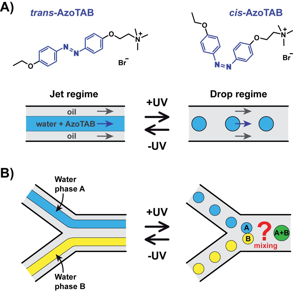
Concept for the photocontrol of water drop generation and mixing. A) AzoTAB surfactant undergoes a trans–cis isomerization upon illumination at 365 nm (+UV). When dissolved in the water phase of a biphasic microfluidic flow, there is a range of flow rates for which trans-AzoTAB corresponds to a jet regime (−UV) and cis-AzoTAB to a drop regime (+UV). B) UV-induced fragmentation of two unmixed water jet regimes in a Y-junction results in the formation of two population of drops to be mixed downstream.
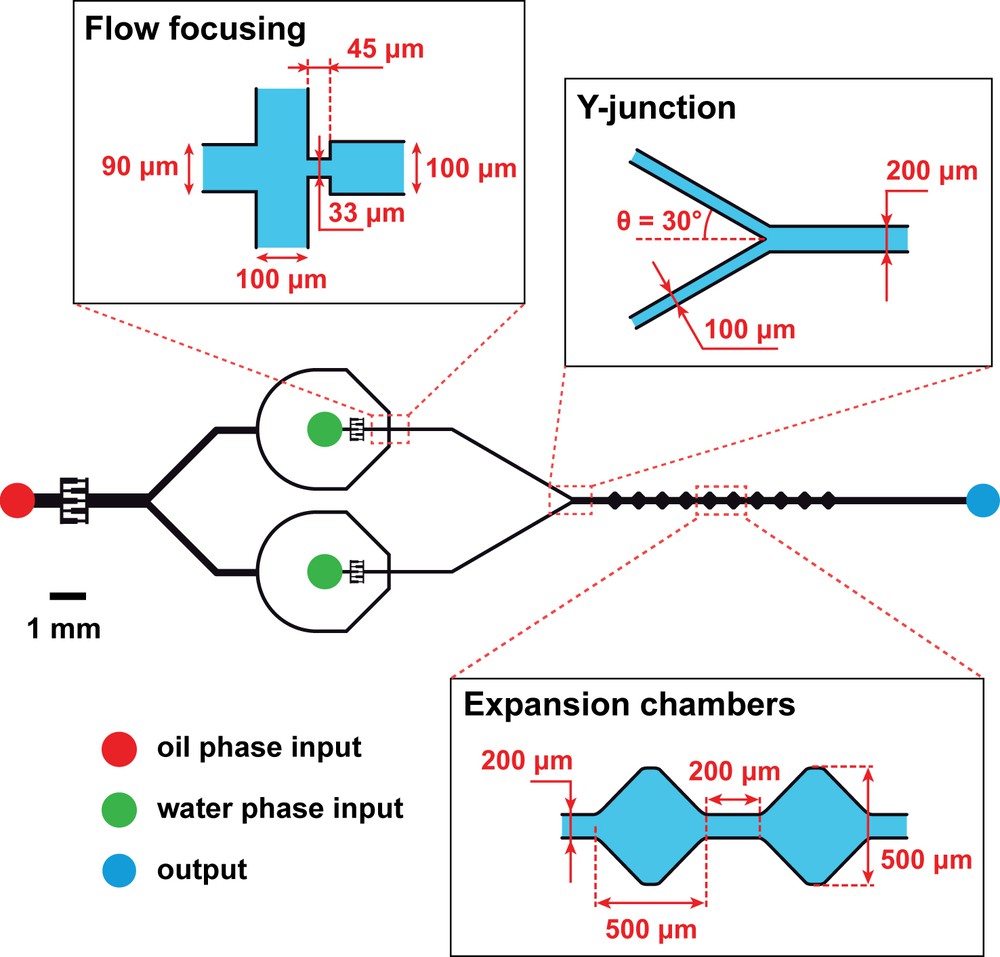
Experimental set-up. Schematic representation of the dual flow-focusing microfluidic device (drawn to scale) with zooms on its three essential modules: two identical flow-focusing zones where a biphasic flow is formed, a Y-junction to combine the flows, and 10 identical expansion chambers (numbered from 1 to 10 from left to right) for drop mixing. The oil phase input is oleic acid at a total flow rate fixed at 1 μL min−1 (QOil = 0.5 μL min−1 at each flow-focusing zone) for all experiments. The water phase inputs are AzoTAB solutions at different concentrations and flow rates (QW). The device is made of polydimethylsiloxane (PDMS) bound to glass and baked at 150 °C for 1 h to be hydrophobic. The channel has a constant height of 50 μm. When desired, the UV illumination (365 nm) is applied using a LED placed 1 cm above the flow-focusing modules.
3.2 Flow regime and photocontrol
We first used an AzoTAB solution as the water phase and we varied the AzoTAB concentration and the water phase flow rate QW. For each experiment, we used the same QW at each water phase input. Within the range of experimental conditions that we investigated, only three flow behaviors were distinguished at the Y-junction. The first behavior was two parallel jet regimes, referred to as a dual jet regime (Fig. 3A). The second type consisted of two trains of drops flowing in parallel, which we called a dual drop regime (Fig. 3B). The dual jet and dual drop regimes were defined as stable flow regimes when they could be maintained for more than 30 s under given experimental conditions. The third type of behavior was an unstable regime when at least one of the two flows at the Y-junction was alternating randomly between a drop and a jet regime. Note that we have never observed any stable flow regime consisting of a stable jet parallel to a stable train of drops, which is explained by the fact that the two flow-focusing modules were always used simultaneously with the same flow rates (QOil and QW) and AzoTAB concentration conditions.

The two stable flow regimes observed at the Y-junction. Representative bright field microscopy images of the dual jet regime (A) and the dual drop regime (B).
We then systematically analyzed the flow behavior at the Y-junction and built a phase diagram where the flow regime was plotted as a function of QW, with (+UV) or without (−UV) illumination at 365 nm (Fig. 4). For the two AzoTAB concentrations investigated here, we found that the flow regime was successively i) dual drop, ii) unstable, and iii) dual jet when QW was increased, for both −UV and +UV conditions. Interestingly, the dual drop regime was maintained for a larger range of flow rates when UV was applied. As a consequence, we could identify a range of water flow rates for which we obtained a stable dual jet regime without UV and a stable dual drop regime under UV illumination (dashed box in Fig. 4). To our knowledge, it is the first time that a dual biphasic flow regime can be controlled by the application of a light stimulus. We also found that the concentration of AzoTAB was important in this process. Increasing [AzoTAB] led not only to a stabilization of both dual drop and dual jet regimes but also to a marked decrease of the typical QW range at which UV light switched the regime from a stable dual jet to a stable dual drop. To interpret the effect of AzoTAB and light conditions on the flow behavior, we first compared the amplitude of surface tension, which favors the fragmentation of the water phase into drops, to that of viscous forces, which favor the stretching of the water/oil interface and therefore the formation of continuous jets. The balance between these two forces can be estimated by computing the capillary number Ca = μv/γ at each flow-focusing module, where μ and v are the viscosity and the velocity of the oleic acid phase and γ the surface tension between oleic acid and the AzoTAB solution [23]. Under our experimental conditions, with QOil = 0.5 μL min−1, μ = 27.6 10−3 kg s−1 m−1 and γ ≈ 7 mN m−1 (−UV, trans-AzoTAB) or γ ≈ 8 mN m−1 (+UV, cis-AzoTAB) [12], we found Ca ≈ 8.8 10−3 and 7.7 10−3 for −UV and +UV conditions, respectively. These Ca values indicate that surface tension was largely predominant over viscous forces in our experiments, regardless of QW and of the illumination conditions. Therefore, surface tension and viscosity effects are not enough to explain i) the appearance of the dual jet regime at high QW and ii) the effect of UV light on the flow regime (dual jet-dual drop transition). We showed in the past that, with a single-flow focusing configuration, the wetting properties of the water phase on the microfluidic substrate are instrumental in directing the flow regime [20]. In particular, we demonstrated that the adsorption of trans-AzoTAB at the water/substrate interface was stabilizing the jet regime by increasing the wetting of the water phase on the substrate. We can thus explain the occurrence of a dual jet regime at high QW when viscous forces are strong enough to stretch the interface together with a strong wetting on the substrate that stabilizes the formation of each jet regime. A similar argument can be used to explain the effect of AzoTAB concentration: increasing concentration leads to a stronger AzoTAB adsorption, which enhances the wetting of the water phase on the substrate, inducing the formation of a stable dual jet regime at lower QW. For the effect of UV illumination, it is also interesting to analyze how the wetting is affected by the AzoTAB conformation. For the same AzoTAB concentration, the water phase wets the substrate less with cis-AzoTAB than with trans-AzoTAB due to the higher polarity of the cis isomer. As a consequence, cis-AzoTAB stabilizes less the jet regime than trans-AzoTAB and, regardless of AzoTAB concentration, the appearance of the dual jet regime is always observed at higher QW with cis-AzoTAB (+UV) than with trans-AzoTAB (−UV).
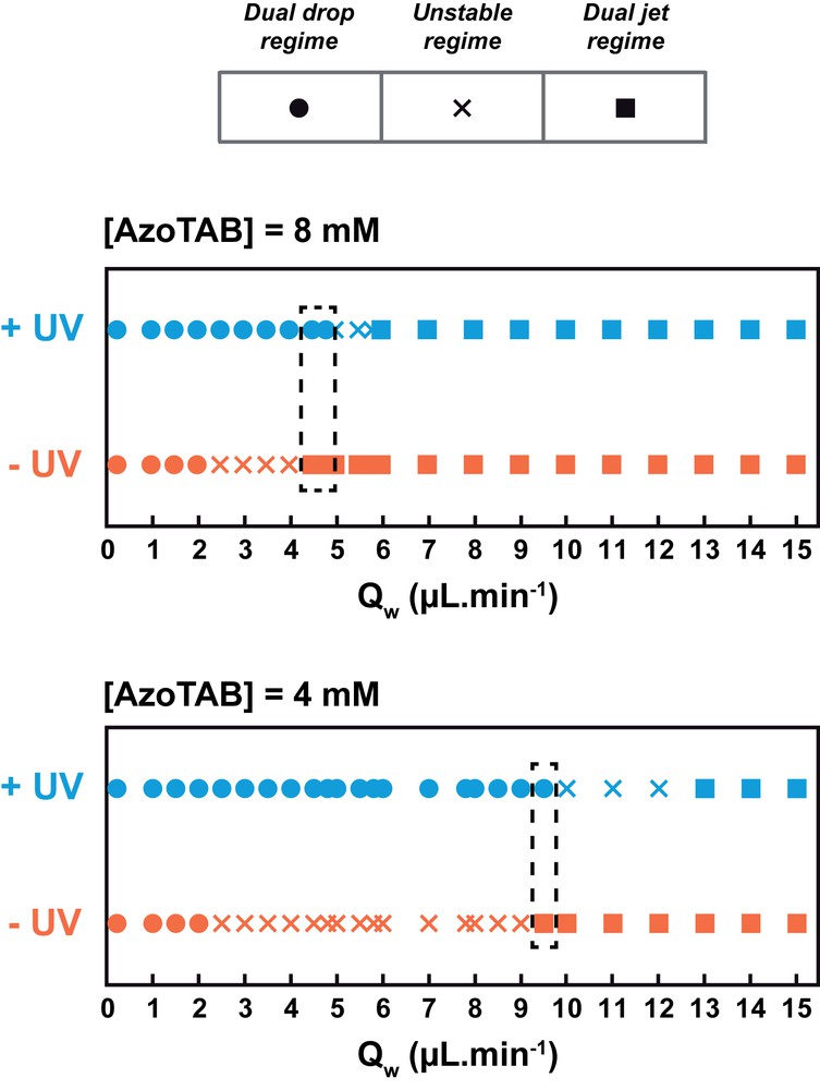
Flow regime phase diagram. Flow regime as a function of the water phase flow rate (QW) for two different AzoTAB concentrations, with (+UV) or without (−UV) illumination at 365 nm. The dashed box indicates the range of QW for which the flow can be switched from a stable dual jet regime to a stable dual drop regime upon UV illumination.
3.3 Photoreversible dual drop generation
The phase diagram of Fig. 4 shows that there are flow rate conditions for which the flow regime can be switched from a stable dual jet regime to a stable dual drop regime by application of UV light at 365 nm. To characterize the dynamics and reversibility of this process, we followed the flow regime in such conditions and studied the flow response to successive applications/removals of UV illumination at fixed water flow rate (QW = 4.8 μL min−1) and AzoTAB concentration (8 mM). Fig. 5 and Movie S1 show that the flow regime was successfully switched between the dual jet (−UV) and the dual drop (+UV) regime in a dynamic and reversible manner, with a characteristic time of about 4.5 s to switch from one stable regime to the other. To our knowledge, this is the first time that such a reversible dual flow behavior controlled by light is reported.
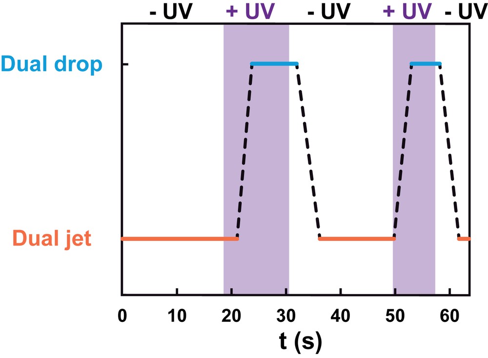
Reversible photocontrol of the flow. Flow regime as a function of time for successive applications (+UV) and removals (−UV) of illumination at 365 nm. Dashed lines correspond to the transition from one stable regime to the other. The data correspond to Movie S1. Experimental conditions: QW = 4.8 μL min−1; [AzoTAB] = 8 mM.
The following is the supplementary data related to this article:
3.4 Photo-induced drop fusion and mixing
Then, we explored the possibility to exploit the photocontrol of the dual biphasic flow regime for the control of drop fusion and mixing by light. To this end we fixed the water flow rate (QW = 4.8 μL min−1) and the AzoTAB concentration (8 mM) and we added methylene blue (0.2 wt%) to the water phase of the lower flow-focusing module to distinguish the two water phases coming from each flow-focusing module. At this concentration, the methylene blue solution strongly absorbed visible light. By microscopic observation through a monochrome camera, the water phase coming from the lower flow-focusing module appeared darker than the water phase without dye (Fig. 6). First, we analyzed the flow behavior at the Y-junction and found that the presence of methylene blue did not affect the UV-induced dual jet-dual drop transition nor the size of the drops. We also observed that the two different water phases never mixed in this zone, regardless of the flow regime, probably due to the laminar flow conditions imposing a parallel motion of the two flowing water phases. A markedly different behavior was observed in the expansion chambers (Fig. 6A). In the absence of UV and regardless of the chamber position, the two water phases formed well separated jets, which slightly widened in the center of the chamber due to a decrease of the flow velocity, but they never came into contact nor mixed (Fig. 6A, top). In the absence of UV, the two water phases were thus totally separated all along the device. In contrast, upon application of UV, drops were formed for both water phases and the drop behavior was strongly affected by the presence of the expansion chambers (Fig. 6A, bottom). The expansion geometry induced both a velocity variation and a transversal motion of drops that provoked drop–drop collisions and fusion events. Qualitatively, we observed in chamber 1 two distinguishable populations of nearly monodisperse drops, one with a high mean pixel intensity (drop without dye) and the other one with a low mean pixel intensity (drop containing methylene blue). Interestingly, when the drops moved through several consecutive chambers, their characteristic size tended to increase and their average pixel intensity took intermediate values between those of the two populations in chamber 1. These two observations indicate the occurrence of both drop fusion and mixing of the water phases to an extent that increases with the number of chambers that have been crossed by the drops. To quantify this behavior, we analyzed on many drops the size distribution by plotting the distribution of the drop projected surface areas under UV illumination in three characteristic chambers, namely numbers 1, 5, and 10 (Fig. 6B). We found that the sharp distribution in chamber 1 widened with an increase in the chamber position accompanied by a marked shift toward larger drop sizes. For instance, the large majority (91.7%) of the two water phases was dispersed into drops between 150 and 250 μm2 in chamber 1 while in chambers 5 and 10, the majority of the water phases (66.0% and 77.6%) was in the range of 250–550 μm2 and 1500–2700 μm2, respectively. We also analyzed the mean pixel intensity per drop under UV illumination (Fig. 6C). Interestingly, we found that the distribution, which showed two separated sharp peaks in chamber 1 with almost no drop having intermediate values (94.7% of the drops had a mean pixel intensity smaller than 0.2 or larger than 0.8), progressively widened with an increase in the chamber position. The larger distribution was observed in chamber 10 where 29.4%, 47.1%, and 23.5% of the drops had a mean pixel intensity in the range of 0–0.2, 0.2–0.8, and 0.8–1, respectively. All these results show that i) no fusion occurred in the absence of UV when the two jet regimes were well separated, ii) UV induced the formation of drops, which fused and mixed inside the expansion chambers, and iii) UV triggered drop formation while the chamber position controls their degree of fusion and mixing. This new microfluidic configuration thus enables the first photocontrol of drop generation, fusion, and mixing in a single device.
3.5 Fusion-triggered mixing
Fig. 6 shows that UV-induced drop formation followed by fusion in the expansion chambers was accompanied by a mixing of the two water phases. To analyze in more detail the evolution of the mixing behavior after drop fusion, we followed by microscopy the temporal evolution of two given drops fusing in the expansion chamber 5 (Movie S2 and Fig. 7). Timelapse observations (Fig. 7A) show that the fusion event was a very fast process. Right after fusion, the fused drop displayed inhomogeneous intensity distribution. About 500 ms after fusion, the fused drop displayed a homogenous intensity profile indicating the mixing of the two water phases. To quantify the evolution of the mixing during this process, we computed the mixing index MI (see Materials and methods), which is a reliable method to characterize the degree of mixing between two phases with distinct intensities [21,24]. With this method, MI = 1 corresponds to fully separated phases and MI = 0 to a perfect mixing of the two phases. Fig. 7B shows that, before fusion, MI was very large (≥0.99) due to the physical separation of the water phases in the two distinct drops. Interestingly, upon fusion, an immediate and marked decrease of MI was observed (MI = 0.73 at t = 127 ms). Then, MI continuously decreased to reach a value of 0.09 at t = 699 ms, meaning that complete mixing was achieved within 572 ms. The characteristic time τ for methylene blue to diffuse from one phase to the other within the fused drop can be estimated as l2/D with l2 being the characteristic diffusion length (here one drop diameter) and D the diffusion coefficient of methylene blue in water at room temperature. With l ≈ 100 μm and D ≈ 5 10−10 m2 s−1, we get τ ≈ 20 s, which is more than one order of magnitude larger than the experimentally measured mixing time. This shows that the mixing inside the fused drop does not proceed by sole diffusive transport. To interpret the fast observed mixing, we suggest that both the fusion and the subsequent deformations of the drop in the expansion chambers provoke chaotic advection [2,25] that accelerates the mixing of the two phases inside the drop.
The following is the supplementary data related to this article:
4 Conclusion
The new dual flow-focusing microfluidic device configuration described in this study allowed us to generate stable dual jet and dual drop regimes in a reliable manner. We showed that these flow regimes were controlled by a combination of viscous forces and interfacial forces at both liquid/liquid (water/oil) and liquid/solid (water/substrate) interfaces. Introducing AzoTAB photosensitive surfactant allowed us to control the wettability of the water phase in a photodependent manner. As a consequence, the flow regimes were dependent on illumination conditions and we identified a range of flow rates where the flow regime could be dynamically and reversibly switched between a stable dual jet and stable dual drop regime upon application of illumination at 365 nm. This novel method of photo-induced dual drop generation was applied on two water phases of different compositions. We showed that, in the absence of illumination, the two phases were well separated and never mixed. Applying UV light induced the generation of two population of drops, which fused and mixed by hydrodynamic effects inside expansion chambers. We found that the mixing of the two water phases was particularly efficient due to chaotic advection inside the fused drop, leading to a characteristic mixing time one order of magnitude smaller than diffusion. We believe that several concepts of this study will be useful for future development of smarter lab-on-a-chip devices with improved flexibility and portability features. The dual flow-focusing concept can be easily implemented in many microfluidic configurations, adding parallel capability to the well-established high-throughput screening performance of flow-focusing based approaches [2,3]. The concept of expansion chambers to fuse and mix light-generated drops is also interesting as it combines a precise and flexible trigger (light) with the robustness of passive mixing (by chaotic advection in chambers). The possibility to control in a single device, by a straightforward LED light stimulus, the three key-operations of drop microfluidics – drop generation, fusion, and mixing – will greatly simplify the management of picoliter sample drops, which traditionally relies on multiple and complex actuation strategies. This method could also be highly useful to drive the flow behavior inside truly portable, autonomous microfluidic devices, for instance using embarked pressure load systems [26] to generate the main flow streams.
Acknowledgments
This work was supported by the European Research Council (ERC) [European Community's Seventh Framework Programme (FP7/2007-2013)/ERC Grant agreement no. 258782] and the Mairie de Paris [Emergence(s) 2012].