

1 UF6: a key compound for nuclear industry
Uranium hexafluoride (UF6) plays a key role in the nuclear industry. Its annual worldwide production of around 60,000 tons in 2010 is devoted to this application [1,2]. Most of the 500 commercial nuclear power reactors in the world today require uranium enriched in the 235U isotope for their fuel; only 235U can release energy by fission. Both the commercial and under development isotopic enrichments involve a gaseous uranium compound. The commercial processes are diffusion and centrifugation, whereas laser excitation is under development. UF6, the only volatile compound of uranium, sublimes at 56.2 °C despite its high molecular weight. This property is combined with the relative chemical stability of UF6. Moreover, fluorine has only a single stable naturally occurring isotope (19F) and only two isotopomres of UF6 exist and differ in their molecular weight only because of the presence of 235U and 238U [1–5].
1.1 Isotopic enrichments
Uranium is a chemical element present in almost all media (rocks, water, etc.) often in very small proportions (from several hundreds of grams to several kilograms of uranium per ton of extracted minerals). However, in some exceptional cases, uranium content may reach few tens of kilograms of extracted minerals. Whatever uranium content in the minerals is used for its extraction, U is present mainly in two isotopic forms, namely 0.71% of 235U (fissile) and 99.28% of 238U (fertile). Uranium with 235U content between 3% and 5% is required for fuel in nuclear power reactors. Therefore, a uranium enrichment process is necessary. UF6 is a colorless gas above 64 °C and a white solid at room temperature. The liquid phase exists only under pressures greater than about 1.5 atm and at temperatures above 64 °C. The triple point of UF6 at 64 °C is used whatever the enrichment processes, gas diffusion, centrifugation, or laser excitation. All these processes are described below.
The gaseous diffusion process is based on the small mass difference between the two uranium isotopes. UF6 gas is forced to diffuse under pressure through micropores of ceramics with a radius lower than the main free path of the molecules. The lighter molecules (235UF6) diffuse slightly faster than the 238UF6 molecules. Therefore, the enriched fraction is injected to the upper level and the depleted fraction comes back to the lower level. This process is repeated in cascade more than 1000 times to reach UF6 containing 235U between 3% and 5%.
The gaseous diffusion requires much higher energy than the gas centrifuge process. Moreover, although the volume capacity of a single centrifuge is much smaller than that of a single diffusion stage, its efficiency to separate isotopes is higher. Centrifugation stages are also performed in cascade (centrifuges in parallel) but their number may only be 10–20. For these reasons, the use of diffusion process then decreased from 50% in 2000 to 25% in 2010 [1]. At the same time, centrifugation part increased to 40% in 2000, 65% in 2010, and 100% in 2015.
The centrifugation process also takes benefit from the mass difference between the two isotopes of gaseous UF6. The later is introduced into centrifuge rotating at a high speed (50,000–70,000 rpm). Thousands of cylinders are positioned in series. The lighter molecules with 235U are concentrated at the center of the centrifuge (the heavier ones with 238U increase in concentration toward the outer edge of the cylinder). A vertical separation is established with a gradient from the lighter at the top to the heaviest at the bottom. The countercurrent flow set up by a thermal gradient enables enriched product to be drawn off axially. The enriched fraction is collected from the head of the centrifuge and the depleted one at the bottom.
Laser enrichment processes are under investigation and the part of enriched U from this technique is expected to reach several percents in 2020. Photoionization may be performed either on uranium metal or on UF6. In the atomic process, a powerful laser is used to ionize atoms in uranium metal vapor. The laser frequency is tuned to ionize 235U atoms but not 238U ones resulting in an electron ejection. The positively charged 235U ions are then attracted to a negatively charged plate and collected. The laser may act on U-containing molecule; its frequency tuning allows the breaking of one UF bond involving 235U and not 238U. The photodissociation of 235UF6 results in solid 235UF5+, which can be easily separated from the unaffected gaseous UF6 molecules containing 238U atoms.
The enriched UF6 is then converted by chemical reduction to uranium oxide (UO2) packaged as small pellets of 10 g. After sintering at high temperature, these pellets are then introduced in long hermetically closed metallic tubes (typically up to 4 m long) composed of zirconium alloys. Many fuel rods constitute a fuel assembly, which is ready to be loaded into the nuclear reactor. Depleted UF6 (238U enriched UF6), which is useless until now, is then stored as such or hydrolyzed into depleted uranium oxide U3O8 according to the following reactions:
| (1) |
| (2) |
Storage, as well as hydrolysis, is costly. Moreover, reactions may occur with containers. It is of primary importance to investigate the surface reaction of UF6, both in the gas and liquid phases, with metallic containers. Whatever the technology used, any volatile impurities in UF6 disturb the enrichment process as well as the corrosion in UF6, the purification must be deeply investigated. With such aim, the physical–chemical properties of both UF6 and the intermediate uranium fluorides must be considered. The intermediate fluorides are compounds of formula UFx, where 4 < x ≤ 5. U4F17 (=UF4.25), U2F9 (UF4.5), and UF5 have been reported as distinct compounds. This will be discussed in the following section.
1.2 UF6 synthesis and physical–chemical properties
Various fluorinating agents may be used for the synthesis of UF6: gaseous fluorine F2, halogen fluorides, either liquid or gaseous (ClF3, BrF3, BrF6, IF7, etc.) [6], certain metal fluorides (CoF3), and hydrogen fluoride [7,8]. Katz and Rabinowitch [9] and Tananaev et al. [7] review the numerous routes. The panel of precursors using F2 gas in the 200–400 °C range is also wide: metallic U, uranium carbide, U3O8, UO2, UF4, intermediate fluorides, uranyl fluoride, double salts of the type KUF5 and K2UF6, and sodium diuranate. Fig. 1 summarizes the various routes to prepare UF6 using F2. Both liquid and gaseous halogen fluorides (ClF3, BrF3, BrF6, and IF7) are efficient to prepare UF6 starting with metallic uranium [6].
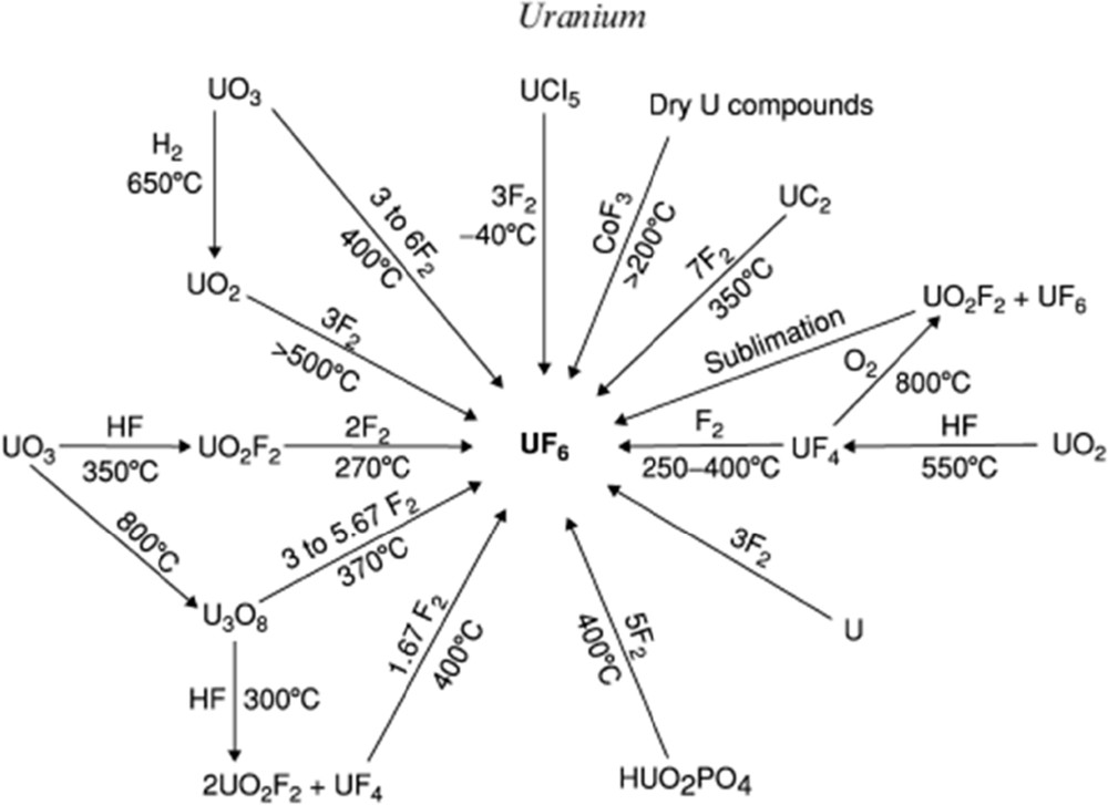
Synthesis routes of UF6 using F2 as a fluorinating agent [8].
Anhydrous hydrofluoric acid must be combined with an additional step with F2 to increase uranium oxidation state to +VI as in the industrial process (see below). Nevertheless, a route starting with uranium pentachloride, UCl5, is reported [6]. It involves the double disproportionation of UF5 formed from UCl5 with HF. UF5 forms UF6 and U2F9; the latter disproportionates into UF6 and UF4 (heating allows the separation of solid UF4 and UF6).
The industrial process to obtain UF6 from the ores takes place according to the following steps: (1) conversion of U3O8 into UO2(NO3)2 using HNO3, (2) synthesis of UO3, and (3) reduction into UO2. In the two last steps, UO2 with hydrofluoric acid (HF) is converted to UF4 and then the oxidation with fluorine gas finally yields UF6.
| (3) |
| (4) |
The very exothermic conversion of UF4 to UF6 is performed in a flame reactor where temperature of about 1100 °C can be reached.
Uranium is only weakly radioactive and the chemical toxicity of UF6 is more significant than its radiological toxicity. UF6 is an oxidant and a mild Lewis acid [10–13]. It reacts with many elements such as Al, Ga, C, and so forth to form their fluorides and attacks many metals except Ni and Al on which a passivating and protective metal fluoride layer is formed. In other words, UF6 is a strong fluorinating agent. It does not react with oxygen, nitrogen, carbon dioxide, and halogens (in vapor phase). However, it is very hygroscopic and reacts with water to give uranyl fluoride (UO2F2) and HF. Uranium hexafluoride forms a very corrosive material (HF, hydrofluoric acid) when exposed to moisture.
UF6 being a strong fluorinating agent, its reaction with metallic uranium results in intermediate uranium fluorides according to the reaction
| (5) |
The resulting compounds depend on both the temperature and the pressure of UF6. Nevertheless, the products are unstable in absence of UF6 whatever the composition, that is, x in UFx. UF4 and UF6 are then formed. Reaction of either F2 or UF6 with solid UF4 results also in intermediate uranium fluorides [7,14,15]. The reaction
| (6) |
| 2U4F17 + 2H2O → 7UF4 + UO2F2 + 4HF | (7) |
1.3 AREVA/CNRS/UCA joint research laboratory
Along the nuclear fuel cycle, different surfaces are in contact with UF6, either in the gas or in the liquid phase. Among them, metallic surfaces of the fluorination reactors, cooling systems (for the liquefaction of UF6), and storage containers may react with UF6 in particular when HF is present. Moreover, to increase the efficiency of the process the removal of volatile impurities is important before the enrichment step. Chemical filters with a high specific surface area (SSA) may be used for such aim resulting in UF6/filter reactive interface. Finally, the diffusion effect of the fluorinating agent of UF4 during the preparation of UF6 involves also different interphases F2/UF4, UF6/UF4, UF6/intermediate fluoride, and so forth These interfaces, and the reactivity of UF6 with the surface of different substrates are investigated in the AREVA/CNRS/UCA joint research laboratory since 2004 (located both at the Institute of Chemistry of Clermont-Ferrand and in the Research hall in Pierrelatte). The work started with the updating of Agron's diagram in the low pressure range and resulted in a better understanding of the formation of intermediate uranium fluorides. Purification of UF6 using a chemical filter is the second main topic with the establishment of sorption abilities and mechanisms of both volatile impurities and UF6 onto the filter surface. More recently, corrosion mechanisms and kinetics of metallic substrates in the presence of either liquid or gaseous UF6 are under investigation. The present article reviews a selection of results obtained in the laboratory. Interfaces formed by UF6 with chemical filter (purification), carbon (UF6 storage), and metallic substrate (corrosion) will be discussed next.
2 Chemical filter/UF6 interface
Uranium hexafluoride is a key compound of the front-end nuclear fuel cycle. To provide nuclear fuel purity for companies, international standards were established and the allowed quantity of pollutants in nuclear pellets is limited [16]. Pollutants originate from both uranium ore, chemical products used during conversion process, and/or fission products of used uranium. All elements are fluorinated during UF6 synthesis and depending on the element, the volatility and its solubility vary in UF6 [17]. Several techniques allow UF6 purification such as distillation in liquid or gaseous phase [18], gaseous diffusion [19], or chemical reaction involving a redox mechanism [20]. The AREVA Comurhex plant actually performs a chemical purification using tributyl phosphate and nitric acid as purifier agents. The treatment of nitric products is expensive and noxious for the environment. To have a greener process and reduce the industrial maintenance operations, purification with a chemical filter was developed in AREVA R&D facilities.
Magnesium fluoride is well known for its industrial applications as a catalyst [21] or for its optical properties [22]. But MgF2 is also a chemical filter for removal of technetium [23], molybdenum [24], or neptunium fluoride [25] from UF6. For this study, the selected volatile impurity is vanadium oxyfluoride (VOF3). To improve the efficiency of a catalytic agent, high SSA MgF2 is synthesized by a sol–gel process [26,27]. This chemical reaction implies that hydroxyl groups remain in the final product. For VOF3 sorption, pellets furnished by Nippon Puretec (Japan) or postfluorinated by molecular fluorine in the Institute of Chemistry of Clermont-Ferrand are chosen. Sorption performances are tested after exposure at 80 °C during 24 h in a sealed PTFE reactor. Characterization techniques (X-ray diffraction [XRD], solid-state NMR with fluorine, proton and vanadium nuclei, infrared, and Raman spectroscopies) are performed to provide the mechanism involved. Then, the removal of vanadium in a UF6/VOF3 gaseous mixture is performed.
To tailor the physical–chemical properties of a chemical filter, in particular the hydroxyl groups' content and SSA, a fluorination post-treatment was carried out on MgF2. The higher the fluorination temperature, the lower the SSA (Fig. 2) and the lower the OH/F ratio in accordance with the literature [26,27]. This ratio was obtained from a fit of 19F-MAS NMR spectra (see a representative fit in Fig. 3). The increase in fluorination temperature increases the size of pores due to a coalescence phenomenon. Considering the fluorine NMR spectra, a shoulder relative to the interaction between hydroxyl groups and fluorine is present in commercial MgF2 with higher intensity than in the postfluorinated product. From fit of the NMR data (Fig. 3), the chemical formula of the chemical filter is estimated as MgF1.6(OH)0.4 and MgF1.86(OH)0.14 for the raw and postfluorinated samples, respectively. After 24 h of sorption, the amount of vanadium trapped is higher in commercial MgF2 than in the postfluorinated sample. XRD, Raman, and infrared spectroscopies as well as (19F/51V) NMR characterizations point out that hydroxyl groups are consumed while new MgF2−x(VO2F2)x vanadium oxyfluoride species are identified. Then, the suggested mechanism implies a chemisorption process in two steps: an oxygen–fluorine transfer reaction between MgF2−x(OH)x and VOF3 and a substitution of OH groups in MgF2 by vanadium oxyfluoride. Finally, a partial physisorption mechanism occurs at the surface of MgF2 pellets, but the amount of vanadium trapped is smaller than in the chemisorption process.
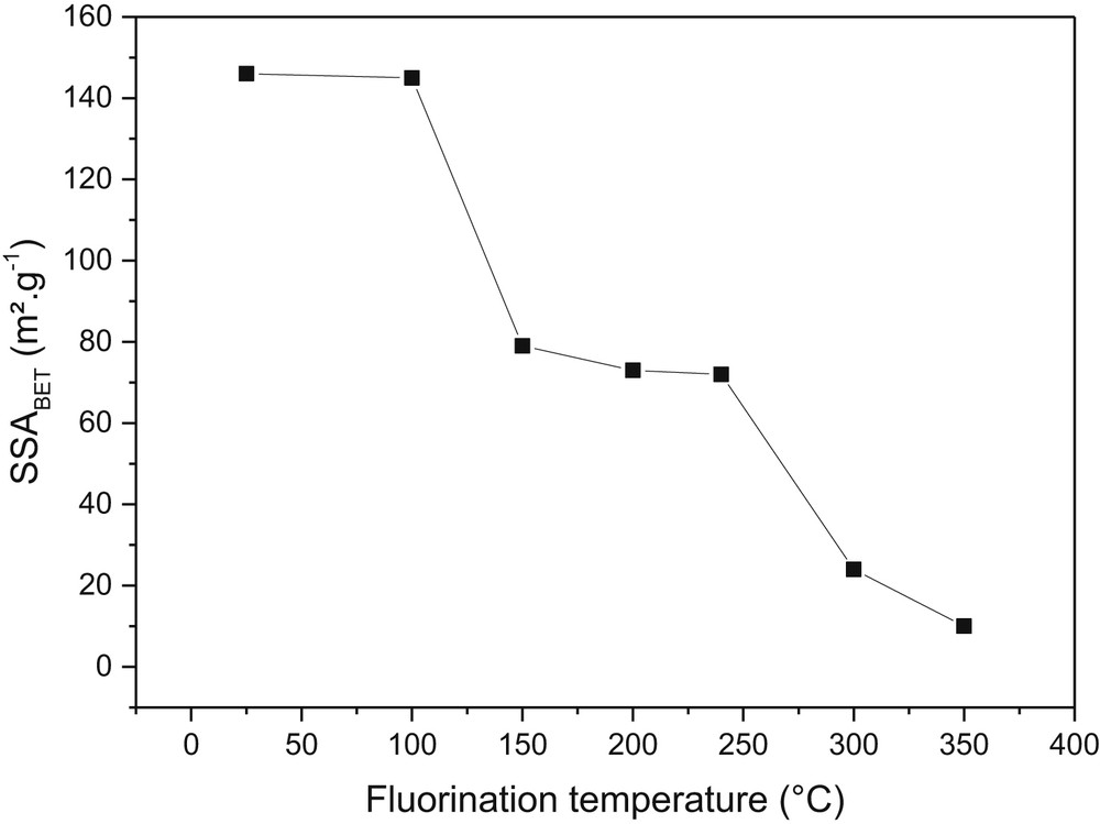
Evolution of an SSA of MgF2 as a function of fluorination temperature.
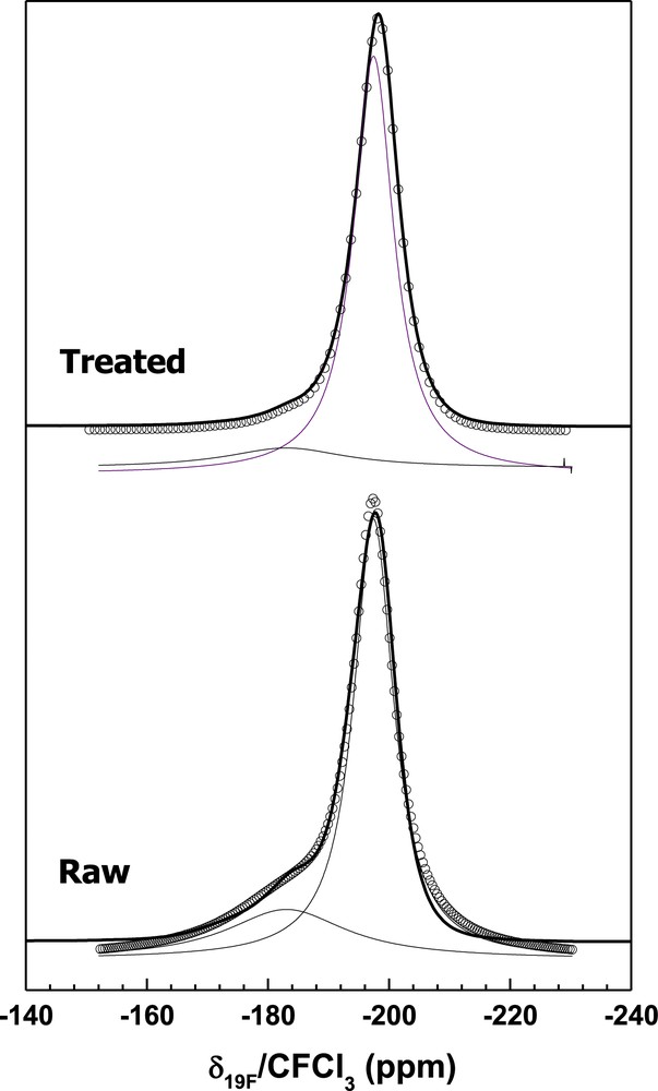
Representative 19F-MAS spectra of commercial and postfluorinated MgF2−x(OH)x (34 KHz).
Several attempts of VOF3 removal in gaseous UF6 were performed at the conversion R&D facility in Pierrelatte. Depending on the fluorination temperature of MgF2, the amount of uranium and vanadium adsorbed is modified (Fig. 4). For a fluorination at 100 or 200 °C, the amount of uranium trapped is higher than the vanadium due to a high OH/F ratio and the affinity of UF6 to hydroxyl groups. For a fluorination at 250 and 300 °C, the quantity of reacting uranium drops whereas VOF3 is better adsorbed. This fluorination treatment allows the selectivity of vanadium regarding UF6 reaction. Above 300 °C, the amounts of pollutant and uranium reacting are reduced because of the diminution of OH groups present in MgF2. The understanding of the mechanism of sorption of volatile species onto MgF2 and their selectivity in comparison with uranium hexafluoride allow the establishment of an operating mode to recycle the chemical filter MgF2 for further sorptions. The recycling process involves a multistep treatment with NaOH as a key reactant to remove vanadium species and to regenerate OH groups.
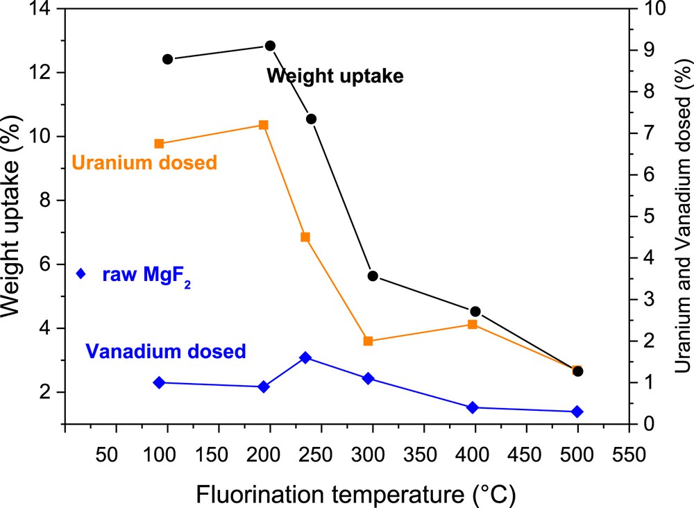
Evolution of the amount of uranium and vanadium trapped as a function of MgF2 fluorination temperature.
3 Carbon/UF6 interface
Except in France where it is converted into U3O8, depleted UF6 (with 238U) is stored as such. A storage strategy may consist in the intercalation into a host matrix. UF6, as many other metallic fluorides [28–30], may be intercalated into graphite. Such a process is thermodynamically favorable [31,32]. KS15 graphite was used as a host matrix to prove the concept.
To reach the lowest graphite intercalation compound (GIC) stage, that is the highest content of U, the UF6/C ratio was adjusted. KS15 graphite was placed in a passivated nickel boat in the reactor. The operating conditions are summarized in Table 1, including duration, temperature, molar quantity, and weight as well as weight and molar uptakes after reaction. The powder was outgassed under primary vacuum for 30 min in a reactor starting at room temperature and during the heating up to the reaction temperature. UF6 was then injected in the reactor. The quantity of UF6 remained constant through a continuous UF6 flux (dynamic mode) except for the manipulation at 140 °C. After a few days of reaction (2–5 days), the reactor was cooled while the UF6 in excess was removed by condensation into a trap cooled at 77 K. The expected GIC was then weighed.
Operating conditions for intercalation of UF6 into graphite.
| Temperature (duration) | 80 °C (5 days) | 100 °C (3 days) | 120 °C (3 days) | 140 °C (2 days) | ||||
| Graphite | Weight (g) | Quantity (mmol) | Weight (g) | Quantity (mmol) | Weight (g) | Quantity (mmol) | Weight (g) | Quantity (mmol) |
| 0.105 | 8.75 | 0.5046 | 42.05 | 0.2827 | 23.56 | 0.1566 | 13.05 | |
| UF6 | Pressure (mbar) | Quantity (mmol) | Pressure (mbar) | Quantity (mmol) | Pressure (mbar) | Quantity (mmol) | Pressure (mbar) | Quantity (mmol) |
| Dynamica | Dynamica | Dynamica | 1240 | 3.17 | ||||
| Uptake | Weight (g) | Quantity (mmol) | Weight (g) | Quantity (mmol) | Weight (g) | Quantity (mmol) | Weight (g) | Quantity (mmol) |
| 1.0255 | 2.91 | 6.3734 | 18.11 | 2.7156 | 7.71 | 1.1076 | 3.15 | |
| C/U | 3 | 2.32 | 3.05 | 4.15 |
a Continuous flux of UF6 (10 mL/min).
The volume expansion and weight uptake evidence the formation of the GIC; the sample color changed from black to blue. As seen in Table 1, the final weight is approximately 10 times higher than the initial one (the molecular weight of UF6 explains these huge uptakes). The weight and molar uptakes allow the C/U ratio to be calculated. XRD analysis underlines the formation of the β-UF5 phase (Fig. 5).
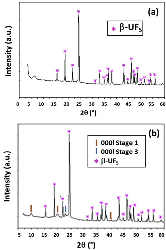
XRD diagram of UF6-GIC prepared (a) at 100 °C for 3 days (C/U = 2.32) and (b) at 140 °C for 2 days (C/U = 4.15).
The intercalation of metal fluorides into graphite takes place through a redox process. Carbon acts as an electron acceptor whereas the fluoride as a donor. The reactive unit consists of 24 carbon atoms. In most of the cases, the intercalation occurs through a direct contact of the fluoride with the host matrix. Nevertheless, the process may be catalyzed by the presence of F2, HF, or Cl2 [28]. Taking into account that the intercalation of UF6 into graphite occurs similarly as for WF6 and MoF6, which exhibit similarities for chemical and crystallographic properties [28], the redox process is
| (8) |
When the process goes further, additional neutral UF6 molecules may be intercalated.
| (9) |
Nevertheless, XRD diagram indicates the presence of β-UF5 phase. The hypothesis suggests that two UF6 reactions may be performed. In accordance with the tendency for disproportionation of uranium fluoride, such process forms UF5 and UF7−:
| (10) |
The intercalation may go further to bring two more UF6.
| (11) |
C6UF6 formula results from this mechanism, that is, a C/U ratio of 6. It is two times lower than the measured one. A higher intercalation rate seems to be formed because the intercalation was performed at temperatures between 80 and 140 °C, instead of room temperature, intercalation being a thermally activated process. Because the pattern of UF5 dominates the XRD diagram, the GIC signature is masked for this sample. UF6 being a strong fluorinating agent, the fluorination of the carbonaceous surface may also occur as
| (12) |
To validate these hypotheses, the addition of UF6 has been controlled (at 140 °C, see Table 1). The resulting C/U ratio was 4.15 in accordance with the lower amount of UF6. The formation of UF5 is also limited, and XRD diagram of the resulting sample (Fig. 5b) exhibits the reflection for both the β-UF5 and UF6-GIC of first stage mainly (Table 2).
XRD data for UF6-GIC (140 °C for 2 days).
| Reflection | d (Å) | Stage |
| 0001 | 8.87 | 1 |
| 0002 | 4.44 | 1 |
| 0004 | 3.88 | 3 |
| 0004 | 2.24 | 1 |
It is interesting to note that the identity period of 8.87 Å is slightly greater than the value given by Hagiwara et al. [32] (8.5 Å). This difference may be explained by the nature of the intercalated species. Hagiwara et al. assumed an insertion mechanism for which only UF6 enters into the graphitic structure, as well as for its thermodynamic calculations. The insertion mechanism proposed here assumes the formation of UF7− in the graphite host. The slightly larger size of UF7− when compared with UF6 may explain the difference in the identity period. The intercalation of UF6 into graphite allows the low-temperature β-UF5 phase to stabilize. Agron's diagram indicates that this phase is stabilized only for temperatures lower than 120 °C. In our case, an intercalation at 140 °C results in the same phase. Moreover, the stabilization of (α or β)-UF5 phase is not possible without equilibrium with gaseous UF6. In the absence of UF6, UF5 decomposes into UF4 and UF6 as for all of the intermediate uranium fluorides (see Section 1.3). In other words, (α or β)-UF5 is stabilized by the graphitic matrix in our study. This opens new routes for both the storage of UF6 and the stabilization of intermediate uranium fluorides.
4 Metal/UF6 interface
The industrial synthesis of UF6 is the hydrofluorination of uranium mining concentrates through a process called conversion. The first stage aims at obtaining UF4 from the mining concentrate, then converting this UF4 to UF6, and finally storing UF6 before its use in the enrichment process. During these stages, the uranium compounds will interact with different metal linings of the fluorination ovens, the piping in the industrial site, and the walls of the containers. Several kinds of metal interactions have thus to be taken into account: the cupronickel Monel of fluorination ovens and the different steel grades of the piping. Given the wide range of temperatures at which the uranium compounds are treated, the structural materials of Comurhex, the industrial conversion plant of AREVA, are submitted to liquid, solid, and gaseous uranium hexafluoride. Although it has been shown that UF6 is highly reactive with ceramics or organic compounds, the different industrial steel grades and cupronickel alloys adapted for industrial appliances due to their cost and mechanical properties are still going to be eventually corroded. Trace amounts of corrosion products can be found in the liquid UF6 and this unwanted pollution can imply a significant deviation from the American Society for Testing and Materials (ASTM) norm and generate a rejection in the final product.
The studies led at joint research laboratory intend to provide some data on the corrosion of metallic alloys in liquid and gaseous UF6. Three types of materials were chosen: nickel and the cupronickel alloys such as Monel, industrial grade steels, and finally pure iron (99.9%). Nickel-rich samples and industrial alloys were studied at first to understand their behavior under different fluorination temperatures, before their test of exposition to gaseous UF6. To contain experiments with liquid UF6, a dedicated experimental setup called CORFU (CORrosion in uranium hexaFlUoride) was designed and built. The constraints of liquid UF6 such as radiological environment, relatively high pressure, and high reactivity with moisture have been thoroughly taken into account with specific devices developed to perform reliable experiments. The corrosion experiments are performed over various time durations, from a few hours to several months. Corroded samples were observed and analyzed by XRD and prepared for further analysis by scanning electron microscopy (SEM) coupled with energy-dispersive spectroscopy (EDS).
The first studies focused on the cupronickel alloys, particularly Monel; they aimed at understanding the corrosion of furnaces during the hydrofluorination of treated uranium mining concentrates. Studies were led on standardized nickel or Monel samples with an emphasis on the role of passivation. Results proved a much higher resistance to gaseous fluorine attack after high temperature passivation. UF6 corrosion was then undertaken on passivated samples. Results show the formation of uranium fluoride crystals, identified as mostly UF4. The crystals grow on top of a NiF2 layer, which is compact for passivated samples, but fragile and porous otherwise (Fig. 6). The NiF2 layer sits atop a copper rich surface of the samples. A proposed mechanism for Monel corrosion was developed. With unpassivated cupronickel alloys, UF6 will react with Ni and Cu at the surface to form the corresponding fluoride species. Although the possibility of the formation of the (NiF2)x(UF6)y can be proposed, it is probable that a nickel or uranium fluoride species play a role in the formation of a brittle NiF2 layer. Copper, on the other hand, would form a highly volatile complex, unstable in UF6 medium, which is easily transported. Gaseous UF6 can diffuse through the porous nickel fluoride layer to continuously corrode the sample. In the case of a passivated sample, however, a compact NiF2 acts as a protection barrier to UF6 and slows considerably any diffusion of the gaseous species to initiate corrosion on the core material.
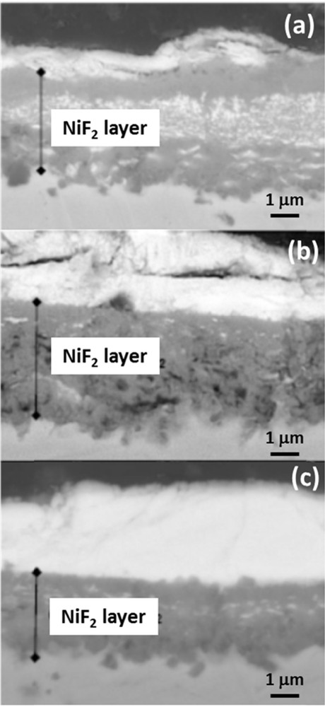
SEM pictures of cross-sections of Monel exposed to UF6: (a) without pretreatment with F2, and pretreated in F2 gas at (b) 200 °C and (c) 450 °C.
Although a mechanism was proposed for cupronickel alloys, the study of industrial steel alloys proved to be subject to a too high number of variables in play. The presence of Mo, W, or Si will cause volatile fluorides to be formed and leave cracked or fragile layers upon which uranium-rich crystals seed. The focus was put on the study of pure iron not only in gaseous but also in liquid UF6 environments corresponding to the state at production temperature. These results were obtained in the dedicated and reliable experimental CORFU setup, combined with procedures that were developed for this purpose. With SEM/EDS and XRD analyses, the corrosion nature was shown to be a layered structure, with an outer uranium fluoride layer on top of iron fluoride nodules or layers (Fig. 7), depending on the corrosion time. From XRD and EDS data, FeF2 was found to be the iron fluoride formed in experimental conditions. It was formed initially as nodules before finally forming a layer subjected to cracks. The uranium fluoride compound's nature was not clearly identified by EDS because it is highly porous; only XRD results tend to show that a continuum of phases from U2F9 to UF5 can be formed. Moreover, it has been shown that the uranium fluoride layer does not protect the metal and that the growth of the corrosion layer is because of the dissociation of UF6 at a solid–solid interface and the diffusion of fluorine through the whole layer.
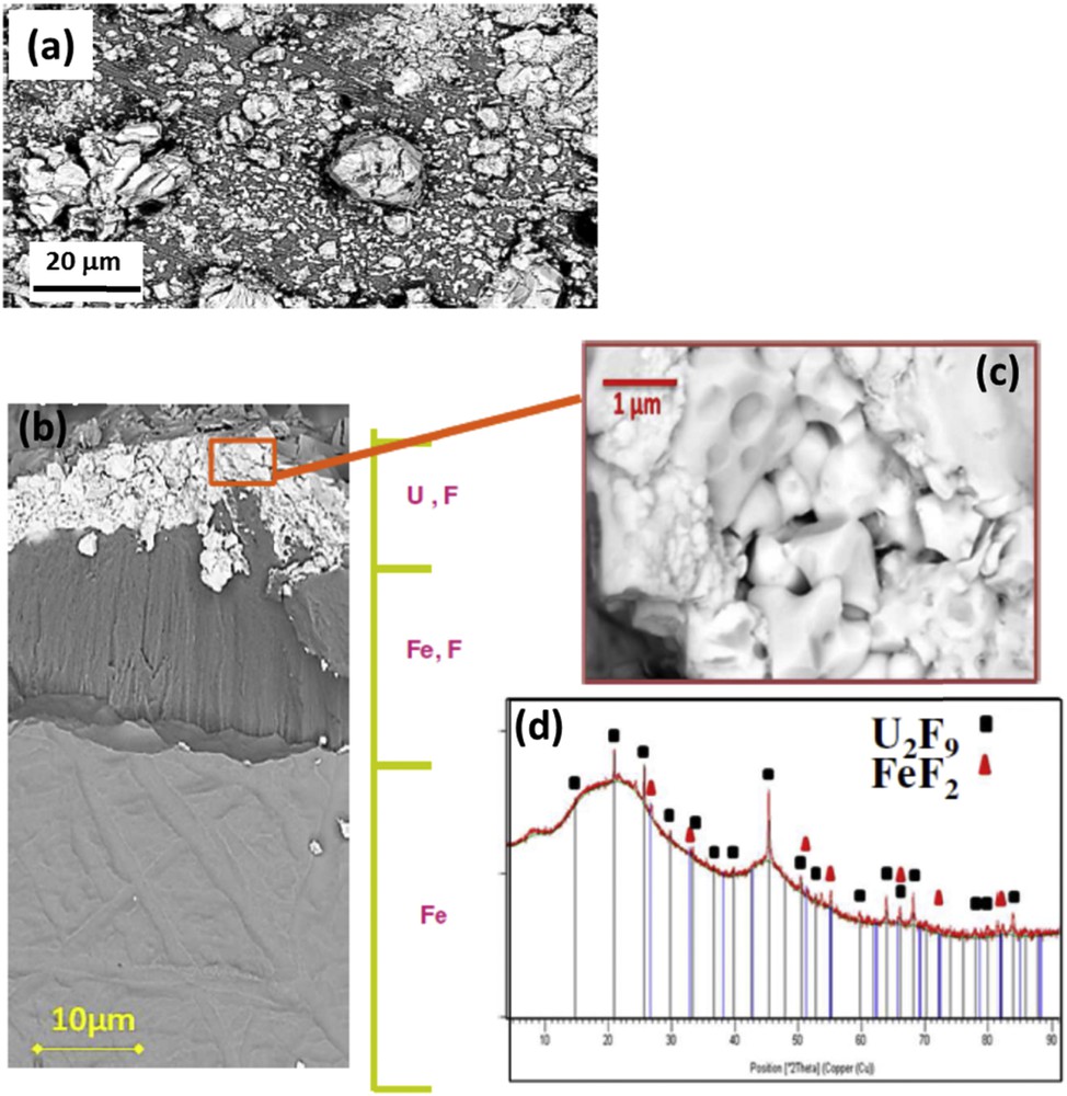
SEM pictures of the continuous layer on an iron sample oxidized in liquid UF6: (a) general view of the corrosion layer, (b) cross-section, (c) zoomed uranium fluoride layer, and (d) XRD pattern.
5 Conclusion
From the studies in the joint research laboratory, the conditions for formation of uranium fluorides, both single and intermediate, and their chemical properties are better understood. This allows different topics to be (re)investigated: corrosion involving either liquid or gaseous UF6, removal of volatile impurities from UF6, and storage of depleted UF6. All these aspects are of both academic and industrial interests. The examples developed in the present article are representative of the joint research laboratory activities.