

1 Introduction
Since the invention of dye-sensitized solar cells (DSSCs) in 1991 [1], these cells are regarded as a cutting-edge technology [2–12] because of their low manufacturing cost and high efficiency [13–24]. Furthermore, these cells are no longer confined to solar panels on the rooftops, because they are invisible, mobile, and foldable [24]. Typically, the “DSSC” converts visible light into electricity via the sensitization of a wide band gap semiconductor using a sensitizing dye steeped in an electrolyte solution, generally the redox couple I−/I3−. Thereby, the photosensitizer constitutes the key element of the cell that performs the double function of light absorption and electron injection into the conduction band (BC) of the semiconductor [25,26].
Up to now, the most successfully used sensitizers in DSSCs are some polypyridyl-ruthenium(II) complexes chemisorbed on mesoporous nanocrystalline TiO2 films owing to their promising photophysical, electrochemical, and redox properties [26–37]. Although, these sensitizers exhibit a broad range of visible light absorption [13] and long-lived excited state [20], they show a poor red response [38]. The urge to improve the performance of these cells has led to different approaches in modifying the sensitizer's structure to increase the extension of solar absorption spectra from the visible to the near-infrared region. It was found in the literature that using the best anchoring group can upgrade sharply the red shift of the absorption spectra and guaranty a better adsorption of the dye on the TiO2 film [9].
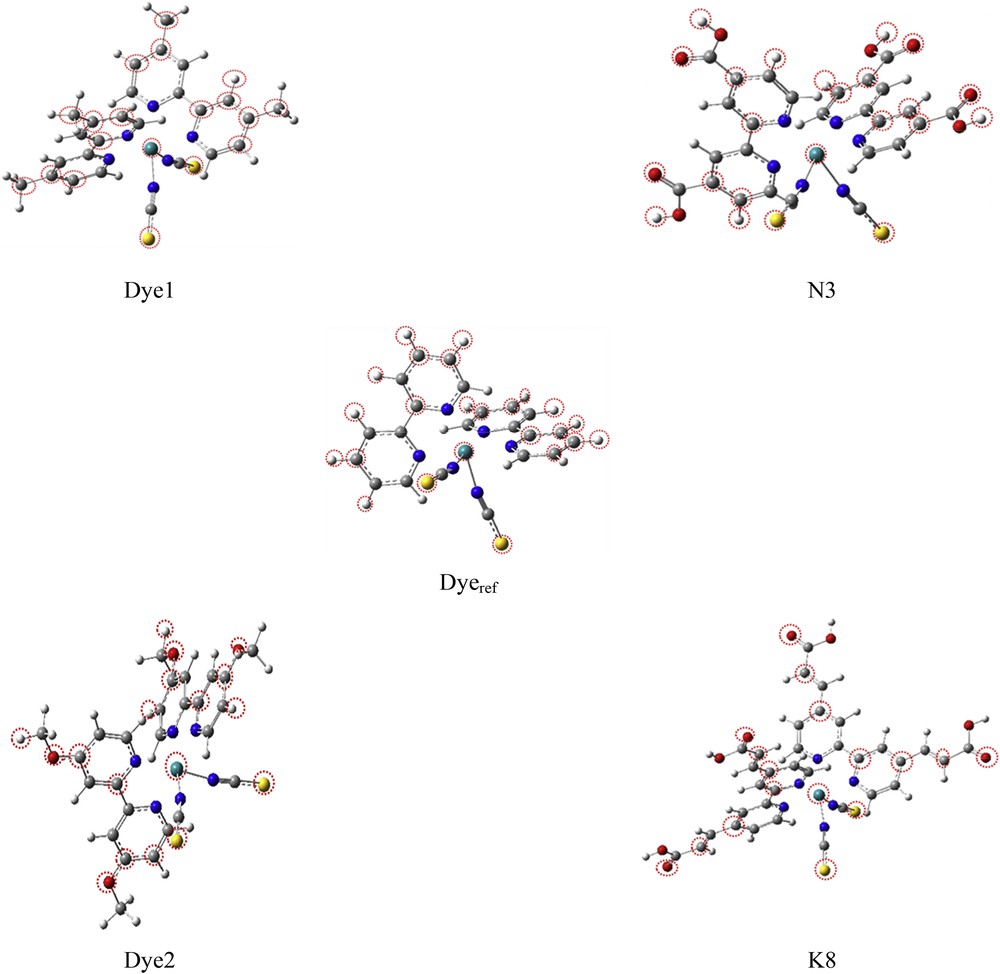
The sensitizers' molecular structure has a key role in the performance of the DSSC [26]. Our study concerns four chromophores, K8, N3, Dye 1, and Dye 2, relatively to a fifth dye (R = H) considered as reference Dyeref (Fig. 1). They share a main structure of two NCS and two bipyridyl (bpy) ligands around Ru center forming the RuN6 core. The central atom Ru(II) adopts a low spin electronic configurations 5s24d6 in which the six electrons 4d undergo two lone pairs and two single electrons. These two last electrons establish a single bond with each NCS ligand. The remaining vacant 3d and the three 5p orbitals accept the nitrogen lone pair of each bpy group leading to dative bonds as it is indicated in Fig. 1. Therefore, we have an 18-electron complex MX2L4.
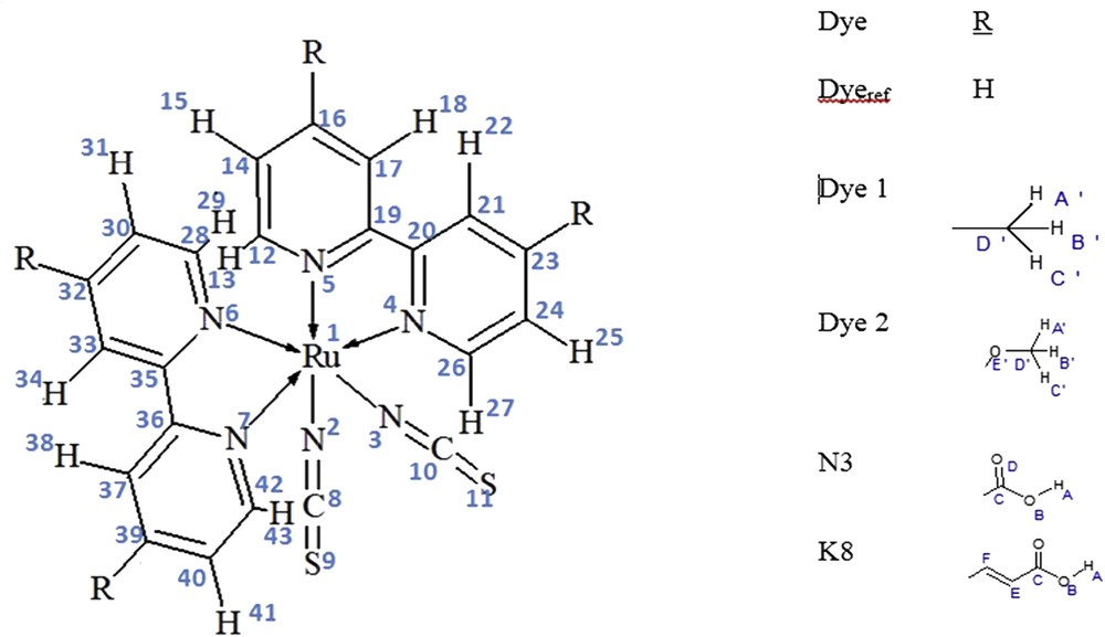
Labeling of studied molecules.
Modeling could be used to accelerate the process of developing DSSCs with a substantial saving of time and experimental resources. In this work, we aim to bring a chemist's point of view in the understanding of the functioning mechanism of a cell. This article deals primarily with the dye and in particular with the ionization process. Our target remains the N3 [12] and K8 [39] cells that differ in nature of the anchoring group. However, if we consider that the good performance of these two cells is, at least in part, because of the anchoring group (which also plays the role of acceptor group because of the attraction of electrons by the electronegative atoms), nothing at best of our knowledge indicates that the electrons injected into TiO2 pass only through the chemical bonds involving the anchoring group [22,40].
N3 or K8 carry several anchoring groups but only one that is linked to TiO2 would play the role of assisting electron injection. The others, attracting the electrons, could even play a harmful role. It is for this reason that derivatives of N3 have been developed in which the bpy groups carry other groups. We can cite OC6H13 [41], nC8H17 [42] (Z907), ter-Butyl (Ru) [42], or other bulky patterns [43].
It is in an attempt to study the effects of groups that we have called added groups and not anchoring. Because CH3 cannot claim this role, we have quoted as a reference a structure without additive groups. For the study to show any effect, it is imperative that the four added groups are similar. CH3 is donor by effect +I and OCH3 is donor by effect +M. Our work focused on an analysis of the local properties of the dye in the ground state, excited state, or during the excitation process. We have tried to analyze each electronic effect on the characteristics of the dye to deepen the knowledge of the ionization mechanism. The injection process will be our next goal. The study will then concern dyes comprising several different added groups including anchoring groups.
Studied dyes differ only by nature of the added group noted R. It is equal to H, CH3, OCH3, COOH, and CHCH-COOH for Dyeref, Dye 1, Dye 2, N3, and K8, respectively (Fig. 1). The selection of this series of dyes was based on the aim that each group introduces a phenomenon assumed to improve the efficiency of the cell. Dye 1 presents an electron donor alkyl group with inductive effect (+I) that may also introduce a steric effect. Dye 2 incorporates an oxygen atom through the methoxy moiety. In this case, the oxygen atom generates not only an inductive effect (−I) but also possibly a donor effect (+M) through its lone pair. The group that is supposed to have the best coupling with TiO2 electrode and so plays the role of an anchoring group is the carboxylic acid group present in dye N3. Finally, the introduction of a conjugated sequence within the carboxylic acid group in the dye K8 is supposed to upgrade the efficiency and the thermal stability of the device [44–47].
To be suitable for DSSCs' applications, dyes must show some intrinsic properties such as (1) a large electronic absorption capacity in the visible region and (2) a preferably donor–acceptor anchoring group directional structure. Thus, the effect of changing the added group was discussed in detail in this study. This will concern properties in both ground and excited states as well as that related to the electronic transition between them. Our main goal was to highlight the relationship between structural or energetic features and intramolecular electronic path associated with the photovoltaic process. This seems to be an important step in the elucidation of the mechanism controlling the efficiency of the cell. We will look for the ability of each dye to undertake an electronic transition or to ionize a particular part of the dye and prioritize the properties at the origin of the photovoltaic phenomenon. To properly locate the electronic distribution in each of these situations, we proceeded to the optimization of the geometry, carried out calculations concerning the atomic probabilities of ionization, the molecular orbitals, and the spectroscopic properties, and then finished by computing certain properties of dyes' work such as mobility, reorganization energy, and redox potential calculations.
2 Computational details
Computations are carried out in the gas phase and ethanol solution. We used the density functional theory (DFT) [48] implanted in the Gaussian (09) program package [49] and time-dependent density functional theory (TD-DFT) [50] extension referred to a B3LYP [51] hybrid functional, at both molecular and the univalent cationic states. Values in ethanol solution were calculated using the polarizable conductor calculation model (CPCM) solvation model [52].
Small core relativistic pseudo-potentials (penta-ζ effective core potentials [ECPs]) were assigned to describe the ruthenium (Ru), and a triple ζ 6-311G* basis set [53] was used including polarization function for all of the other atoms except hydrogen. Hereafter, on the basis of the optimized structures, atomic charges and Wiberg Bond Indexes (WBI) were determined using natural bonding orbitals (NBOs) [54]. Finally, electronic absorption properties were engineered using TD-DFT.
3 Results and discussion
3.1 Ground state
3.1.1 Geometry optimization
It is customary to start a theoretical calculation by the optimization of geometry because it represents an opportunity to validate the choices of the adopted calculation method. In addition, we stated that our main purpose is to describe as fully as possible the electronic path from the photoionization of the dye. Bond length analysis is a powerful tool for describing the distribution of electronic density in terms of bond order and conjugation. In addition, we have extended the analysis to cations created by the ionization process.
The five studied dyes are represented in Fig. 1, in which we have indicated atom labeling of the common part by means of Arabic numbers. We used Latin letters to designate the atoms of the different added groups, which are H, CH3, OCH3, COOH, and CHCH-COOH for Dyeref, Dye 1, Dye 2, N3, and K8, respectively. The optimized structures in their ground state have been reported in Fig. 2. All bond length values are gathered in Table 1. It is clear that the theoretical values are consistent with experimental ones, which validates the adopted level of calculation.
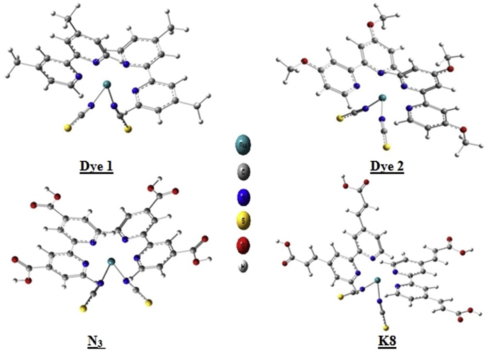
Optimized structures of the studied dyes in their molecular states.
Selected bond lengths of studied dyes in the molecular (M) and univalent cationic (M+) states (expressed in Å).
| Bond | Dyeref | Dye 1 | Dye 2 | N3 | K8 | Experimental [55] | |||||
| M | M+ | M | M+ | M | M+ | M | M+ | M | M+ | M | |
| Ru1-N2 | 2.053 | 1.992 | 2.055 | 1.994 | 2.057 | 1.994 | 2.045 | 1.991 | 2.044 | 1.993 | 2.048–2.046 |
| Ru1-N3 | 2.053 | 1.992 | 2.055 | 1.994 | 2.057 | 1.994 | 2.045 | 1.991 | 2.044 | 1.993 | |
| Ru1-N4 | 2.083 | 2.118 | 2.084 | 2.115 | 2.093 | 2.117 | 2.077 | 2.115 | 2.076 | 2.114 | 2.036–2.058 |
| Ru1-N5 | 2.079 | 2.098 | 2.080 | 2.098 | 2.086 | 2.101 | 2.074 | 2.098 | 2.075 | 2.095 | |
| Ru1-N6 | 2.083 | 2.118 | 2.084 | 2.115 | 2.093 | 2.117 | 2.077 | 2.115 | 2.076 | 2.114 | |
| Ru1-N7 | 2.079 | 2.098 | 2.080 | 2.098 | 2.086 | 2.101 | 2.074 | 2.098 | 2.075 | 2.095 | |
| N2-C8 | 1.177 | 1.184 | 1.176 | 1.184 | 1.176 | 1.183 | 1.178 | 1.184 | 1.178 | 1.184 | 1.162–1.103 |
| N3-C10 | 1.177 | 1.184 | 1.176 | 1.184 | 1.176 | 1.183 | 1.178 | 1.184 | 1.178 | 1.840 | |
| C8-S9 | 1.630 | 1.607 | 1.632 | 1.608 | 1.634 | 1.609 | 1.626 | 1.606 | 1.626 | 1.607 | 1.615–1.685 |
| C10-S11 | 1.630 | 1.607 | 1.632 | 1.608 | 1.634 | 1.609 | 1.626 | 1.606 | 1.626 | 1.607 |
All studied molecules are asymmetrical in shape and they exhibit a distorted octahedral coordination geometry for the RuN6 core. Thus, we will be able to specify the role of the common part of these dyes with the role of each added groups. Bearing in mind that the bond lengths are measurable parameters and sensitive to electronic effects, it is worth to scrutinize their variation from molecular to cationic state. This will give us an idea about the roles of each atom in the internal process leading to the departure of the electron. Indeed, an electron that comes out from a chemical bond weakens it leading to an increase in its length. On the contrary, an electron that comes out from a lone pair will have much less effect on the neighboring chemical bonds.
On the other hand, the departure of an electron will generate a positive charge, which will be shared by a certain number of atomic centers because of the presence of several conjugation zones in each molecule. A positive charge increase can lead to the shortening of the chemical bond in which this atom participates.
We begin by stating that by passing from the added group with the largest donor capacity (R: CH3) to that with the largest acceptor capacity (R: CC-COOH), the Ru-N bonds are strengthened. The bond lengths of molecular states are close varying from 2.045 to 2.093 Å, which is a low variation of about 2.3%. These values are characteristic of simple Ru-N bonds. They do not exhibit the same behavior during the ionization process.
The two distances Ru-N contracted with the nitrogen atoms of the NCS groups have decreased by 2.7% from 2.045 to 1.991 Å for N3, for example. Conversely, the Ru-N distances of the bpy groups increased by 1.8% from 2.077 to 2.115 Å for N3.
The C-S bonds also increased by 1.3%, which promotes the electron departure from the lone pair of the sulfur for the NCS group and the lone pair of the nitrogen for the bpy ligands.
The variations we have just noticed are significant even if they do not give rise to changes in the bond order. For instance, passing the C-C bond from single to double bond produces a variation of about 14%. It is interesting to note that all of the five studied dyes have the same type of variations as those that we observed with N3.
To better quantify these changes in terms of bond orders, we performed a calculation of the WBIs (Table 2). The K8 complex shows the strongest Ru-N bond indexes with a difference of 11% as compared with the Dyeref. The strengthening of these Ru-N bonds is at the expense of NC bonds of the thiocyanate to ligands whose WBIs were diminished from 2.3 in Dyeref to 2.1 in K8. The WBIs, however, retain the same order of magnitudes, confirming our previous conclusion in the absence of an explicit change in the bond orders and highlighting the scattering of the atomic centers through which the electrons are ejected, during the ionization.
WBIs in molecular (M) and univalent cationic (M+) states.
| Bond | Dyeref | Dye 1 | Dye 2 | N3 | K8 | |||||
| M | M+ | M | M+ | M | M+ | M | M+ | M | M+ | |
| Ru1-N2 (NCS) | 0.64 | 0.75 | 0.64 | 0.71 | 0.68 | 0.72 | 0.66 | 0.70 | 0.73 | 0.70 |
| Ru1-N4 (bpy) | 0.57 | 0.53 | 0.57 | 0.58 | 0.52 | 0.58 | 0.59 | 0.57 | 0.65 | 0.57 |
| Ru1-N5 (bpy) | 0.56 | 0.54 | 0.56 | 0.57 | 0.54 | 0.56 | 0.57 | 0.56 | 0.63 | 0.55 |
| Ru1-N6 (bpy) | 0.57 | 0.53 | 0.57 | 0.58 | 0.52 | 0.58 | 0.59 | 0.57 | 0.65 | 0.57 |
| Ru1-N7 (bpy) | 0.56 | 0.54 | 0.56 | 0.57 | 0.54 | 0.56 | 0.57 | 0.56 | 0.64 | 0.55 |
| N2-C8 | 2.30 | 2.18 | 2.31 | 2.23 | 2.28 | 1.64 | 2.28 | 2.23 | 2.09 | 2.23 |
| C8S9 | 1.58 | 1.70 | 1.57 | 1.63 | 1.59 | 1.69 | 1.61 | 1.65 | 1.77 | 1.65 |
3.1.2 Atomic charges and spin densities
To get insight in the charge transfer process involved in the photoexcitation of the sensitizers, atomic charge distribution in both molecular and univalent cationic states are computed and reported in Table 3.
NBO atomic charge (Q) and spin densities (S) of the dyes in molecular (M) and univalent cationic (M+) states.
| Bond | Dyeref | Dye 1 | Dye 2 | N3 | K8 | ||||||||||
| M | M+ | M | M+ | M | M+ | M | M+ | M | M+ | ||||||
| Q | Q | S | Q | Q | S | Q | Q | S | Q | Q | S | Q | Q | S | |
| Ru1 | 0.33 | 0.43 | 0.51 | 0.33 | 0.42 | 0.45 | 0.32 | 0.41 | 0.50 | 0.35 | 0.36 | 0.47 | 0.31 | 0.37 | 0.51 |
| NCS | −0.60 | −0.33 | 0.49 | −0.60 | −0.34 | 0.55 | −0.59 | −0.34 | 0.50 | −0.56 | −0.28 | 0.47 | −0.49 | −0.31 | 0.49 |
| Bpy | −0.04 | 0.08 | 0.00 | 0.11 | 0.20 | 0.00 | 0.27 | 0.36 | 0.01 | 0.09 | 0.25 | 0.07 | 0.20 | 0.32 | −0.01 |
| 2R | 0.42 | 0.45 | 0.01 | 0.11 | 0.16 | 0.00 | −0.39 | −0.33 | 0.00 | 0.07 | 0.12 | 0.00 | 0.02 | 0.14 | 0.00 |
Because we have shown the existence of several centers by which the electrons can be ejected, we have indicated the sum of NBO charges per ligand.
The charge distribution unambiguously shows that the Ru atoms have been optimized as positively charged in both molecular and cationic states with atomic charges in the range of 0.31–0.35 with a slight predominance of the cationic state. In contrast, thiocyanate groups were considered to be negatively charged with a significantly increased charge passing to the cationic state. These values are consistent with the intuition of chemists who consider that the ruthenium is in the degree of oxidation +2 and would be twice positively charged with the configuration 5s04d6. Similarly, each NCS ligand would be negatively charged. The transition to the cationic state spawns a distribution of the positive charge in several centers. It is clear that each ligand (NCS, bpy, or added group) has contributed by nearly 1/5, thus confirming the importance of each ligand in the structure of the studied dyes. The atomic charge of the R groups has also risen in the cationic state.
If these results show the distribution of the positive electric charge on several parts of the molecule as a consequence of the conjugation, the distribution of the spin density shows that the remaining single electron is quasi-equally distributed between the Ru center and the NCS ligands. Then, at the cationic state, the Ru atoms exhibit a spin density of about 0.50 and that of the thiocyanate moiety is of about 0.50 for Dye 1, Dye 2, and N3 and a value of 0.49 for the dye K8 unlike bpy and R groups, which have almost nil spin densities. The spin density values substantiate our prediction of the charge transfer process.
3.1.3 Ionization probability
In this section, we are interested in the variation of the electrical charge on each atom and not each ligand (Fig. 3). We will transform this variation to an estimation of the ionization probability (IPr) of each atom of the dye with the aim to locate the “exit gates” of the electrons and to compare the ability of the dyes in the injection of electrons into the semiconductor oxide BC.
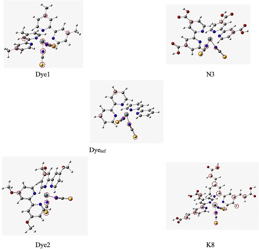
Designation of atoms exhibiting IPr values greater than 5% for the studied dyes in their ground state.
To compute the atomic IPr values (Table 4), the Eq. 1 was used:
| (1) |
The calculated IPr values (>10%) for the five dyes.
| Dyeref | IPr | Dye 1 | IPr | Dye 2 | IPr | N3 | IPr | K8 | IPr |
| Ru1 | 14 | Ru1 | 10 | Ru1 | 12 | Ru1 | 10 | Ru1 | 10 |
| S10 | 33 | S10 | 29 | S10 | 32 | S10 | 30 | S10 | 23 |
| S11 | 33 | S11 | 29 | S11 | 32 | S11 | 30 | S11 | 21 |
The correlation between the different functional groups and the reference unambiguously shows that the addition of the Me group does not seem to be decisive because it does not cause significant changes in the IPr as compared to the reference.
3.2 Description of electronic transitions
3.2.1 Molecular frontier orbitals
To further understand the charge transfer process, there is a quest to have a look at the molecular frontier orbitals. Experimental determination of their energies is extracted from ultraviolet photoelectronic spectroscopy. Highest occupied molecular orbital (HOMO) and lowest unoccupied molecular orbital (LUMO) energy values of the dye N3 [56] are equal to −5.47 and −3.93 eV, respectively. The corresponding optical gap is about 1.54 eV. Our corresponding calculated values (Table 5) for N3 are equal to −5.035, −3.413, and 1.622 eV. We can conclude that our calculation method describes correctly the energetic behavior of N3 and that our predictive values for the other dyes are reliable.
Electronic absorption of the studied dyes.
| Dye | λ(nm) | Energy (eV) | f | Attribution |
| N3 | 373 | 3.32 | 0.1510 | H-5 → L + 3 (+55%) H-4 → L + 2 (+36%) |
| 446 | 2.78 | 0.186 | H-6 → L + 0 (+70%) H-5 → L + 1 (+21%) | |
| 670 | 1.85 | 0.06 | H-0 → L + 3 (+55%) | |
| K8 | 365.5 | 3.39 | 0.0807 | H-5 → L + 2 (+86%) |
| 416 | 2.98 | 0.1008 | H-6 → L + 0 (+67%) | |
| 611 | 2.03 | 0.1595 | H-2 → L + 3 (+43%) | |
| 612 | 2.02 | 0.1506 | H-2 → L + 4 (+43%) H-3 → L + 3 (+22%) | |
| Dye 1 | 328 | 3.77 | 0.0296 | H-6 → L + 2 (+73%) |
| 426 | 2.91 | 0.1181 | H-6 → L + 0 (+75%) | |
| 742 | 1.67 | 0.0265 | H-2 → L + 1 (+92%) | |
| Dye 2 | 346 | 3.59 | 0.0288 | H-6 → L + 2 (+72%) |
| 441 | 2.81 | 0.1039 | H-6 → L + 0 (+48%) H-5 → L + 0 (+20%) | |
| 659 | 1.88 | 0.0233 | H-3 → L + 1 (+98%) |
Indeed, our study has revealed that HOMO and HOMO − 1 of the four sensitizers (Dye 1, Dye 2, N3, and K8) are localized on the Ru atom and the NCS ligands. However, LUMO and LUMO + 1 are located evenly on the two bpy ligands. This distribution confirms that the thiocyanate groups (NCS) and the metal center are donor groups, whereas the bpy ligands are acceptor ones (Figs. 4 and 5). Because bpy groups come into contact with TiO2 by means of the anchoring groups, this result favored the electron injection into the TiO2 BC. This outcome has been well confirmed in the literature [57].
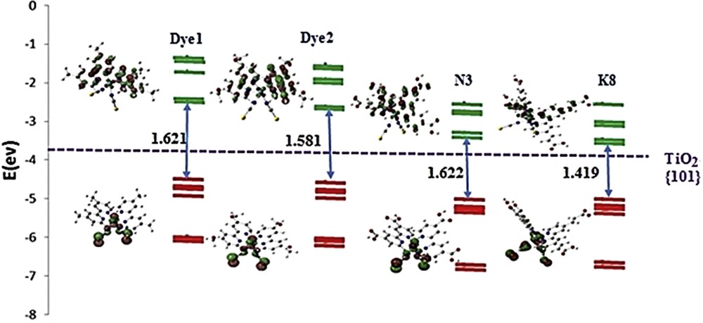
Energy and representation of the molecular orbitals of the studied dyes (HOMO-6 → HOMO (red) and LUMO → LUMO + 4 (green)), HOMO–LUMO gaps, and the position of the BC of the TiO2.

Selected molecular orbitals and energies of the dyes.
From an energy standpoint, the orbital levels are minimally affected for molecules having electronegative groups (Dye 2, N3, and K8), unlike the Dye 1 that shows a higher value of the LUMO, which indicates that the methyl group is less good acceptor than other groups. The small variation in the LUMO energies between N3 and K8 (= 0.006 eV) shows that adding the CC bond has no big influence on this parameter.
Reverting to the DSSC, by comparing the LUMO positions to the TiO2 BC levels, we can conclude that our four chromophores are capable of injecting, in the excited state, an electron in the BC of this semiconductor. The lowest HOMO–LUMO gap of 1.419 eV is assigned to the dye K8, which is beneficial for the charge separation process in the DSSC.
3.2.2 Electronic spectroscopy
There is a quest to explore the absorption spectra of the photosensitizers to allow optical characterization of the sensitizers in the UV–visible region. The electronic absorption of the five dyes in the gas phase was engineered using the TD-DFT method with the hybrid B3LYP functional. The calculated wavelengths (λ), the transition energies, and the oscillator strengths (f) of the molecular orbital were organized according to their energies in Table 5.
The absorption spectra of all chromophores (Fig. 6) properly show the presence of three bands labeled I, II, and III. The bands I and II, centered respectively at 300 and 400 nm, are assigned to multitransitions Ru/NCS to polypyridyl–π* on behalf of the Ru/NCS t2g–π* and t2g–π orbitals. The wideband III ranging from 600 to 700 nm is attributed to metal-to-ligand charge transfer (MLCT) transition. For the dye N3, we can compare our obtained values to experimental ones [58] that are about 538, 398, and 314 nm.

Calculated absorption spectra of the studied dyes.
Theoretical values are higher of about 10–20% than experimental ones measured in ethanol. Other theoretical calculations [59,60] also give overestimated absorbed wavelengths in the gas phase but more accurate values in ethanol. The UV–visible absorption spectrum shows that band III of dye N3 exhibits a hypochromic shift as compared with dye K8 because of the absence of the CHCH group. Furthermore, a hypsochromic shift of the band I of the Dye 1 and the Dye 2 is observed, resulting from the donor effect of their adding groups. Wavelengths were organized according to their energies in the Table 5.
3.3 First excited state
We used a similar process to estimate the atomic IPr for the excited state. In Fig. 7, the most ionized sites in the five excited states of dyes were circled. They correspond to atoms exhibiting IPr values greater than 5% for the studied dyes in their ground state. They are mainly on the metal, the sulfur, the added groups, and the carrier carbons.
Designation of atoms exhibiting IPr values greater than 5% for the studied dyes in their excited state.
It is important to indicate that the atoms of anchoring groups of N3 and K8 participate in the photoionization process. It is the efficient electronic transition of MLCT type, which has enabled this participation.
3.4 Usual descriptors
3.4.1 Ionization potential and electronic affinity
The ionization potential (IP) and electronic affinity (EA) are important factors for the rational design of photovoltaic cells. They can be calculated using the following equations. Adiabatic values are shown in Table 6.
| IP = E(M+) − E(M) |
| EA=E(M) − E(M−) |
Ionization potential and electronic affinity.
| Dye | IP (eV) | EA (eV) |
| Dye 1 | 5.49 | 1.57 |
| Dye 2 | 5.26 | 1.36 |
| N3 | 6.03 | 2.50 |
| K8 | 5.93 | 2.76 |
The insertion of a conjugated sequence within the carboxylic acid group in the dye K8 has led to a decrease in the value of IP and an increase in the EA value (as compared with dye N3), which means that the hole forming ability and the tendency to add electrons are enhanced.
3.4.2 Mobility
The reorganization energy λ is the required energy associated with the relaxation of the molecular structure after the occurrence of electron transfer. Intramolecular transfer of a hole or an electron can be represented by the Eq. 2 in which M and M+/− designate the molecule in its ground state and the cationic or anionic species, respectively:
| (2) |
The corresponding Jablonski diagram is represented in Fig. 8. The reorganization energy of the holes' transport λhole is given by λ1 + λ2. Similar one relatively to the electron is noted λelectron and calculated as the sum λ3 + λ4. The transfer reorganization energy, which is inversely proportional to the mobility of charge carriers [61] of the hole and the electron, is defined by Eqs 3 and 4:
| λhole = λ1 + λ2 = [E0(M+) − E0(M)] + [E1(M) − E1(M+)] | (3) |
| λelectron = λ3 + λ4 = [E0 (M−) − E0(M)] + [E1(M) − E1(M−)] | (4) |
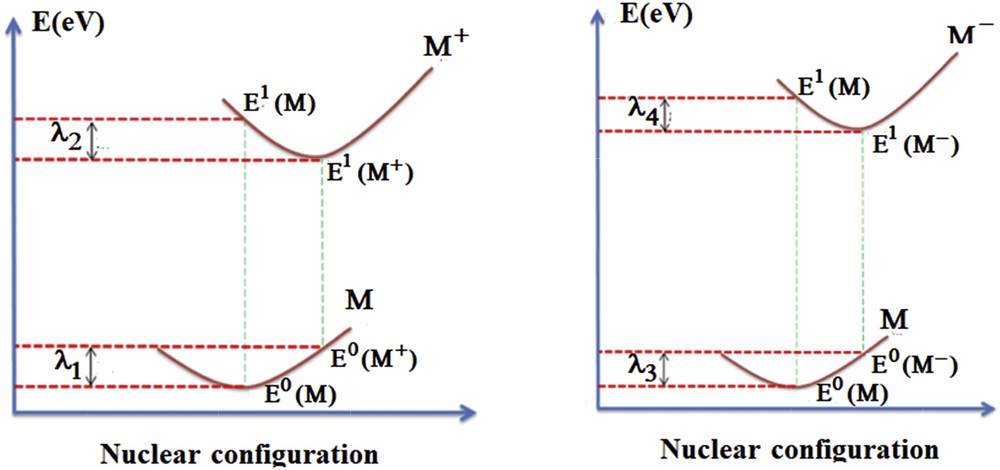
Jablonski diagram of the intermolecular transfer reaction between neutral molecule and cationic/anionic specie.
E0(M) and E1(M+/−) represent the energy of the molecule or the ion in its ground state but E1(M) and E0(M+/−) are the energies of M in the optimized geometry of the ion and the energy of the ion in the optimized geometry of the neutral molecule.
The charge transport rate could be approximated by the Marcus electron transfer theory [62,63] given by the Eq. 5:
| (5) |
Therefore, the transport process is determined by two important molecular parameters: the internal reorganization energy (λ), which must be low for efficient charge transport, and the integral of the intermolecular hole or electron (V) that describes the electronic force coupling between neighboring molecules. The former requires a tight crystal package and good intermolecular pairing between the boundary molecular orbitals, whereas the latter favors long, planned, and conjugated molecules, with less flexible degrees of freedom. Our calculated values are gathered in Table 7.
Reorganization energy values (in eV) calculated for the hole and the electron.
| Dye | λ1 | λ2 | λ3 | λ4 | λhole | λelectron | λtotal |
| Dye 1 | 0.118 | 0.113 | 0.006 | 0.175 | 0.231 | 0.181 | 0.412 |
| Dye 2 | 0.141 | 0.134 | 0.008 | 0.212 | 0.275 | 0.220 | 0.495 |
| N3 | 0.126 | 0.114 | 0.165 | 0.160 | 0.241 | 0.325 | 0.565 |
| K8 | 0.115 | 0.105 | 0.125 | 0.135 | 0.220 | 0.260 | 0.480 |
Experimental [64] reorganization energy value for N3 is equal to 0.554 eV. Our calculated value is equal to 0.565 eV, which is very close to the experimental one. Except for dye K8, the values of λhole are greater than λelectron for all of the dyes, which indicates a better electron transport performance because λ is inversely proportional to the mobility of charge carriers. By comparing Dye 1 and Dye 2, the methyl group (Dye 1) substitution by a methoxy (Dye 2) leads to an increase in both λhole and λelectron and so improves the charge mobilities. Comparing the N3 and K8 dyes, we can deduce that the addition of the conjugation at the anchoring group disadvantages the carrier's mobility.
3.4.3 Redox potential
To find the redox potential, a method related to the thermodynamics was used according to the Scheme 1:
| (6) |
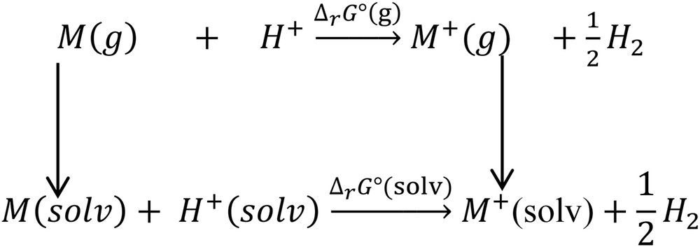
The reaction adopted for the calculation of redox potentials.
Hereafter, the redox potential E0 can be calculated via relation (7):
| (7) |
E0 values of dyes N3, K8, Dye 1, and Dye 2 are depicted in Table 8 and lie in the range from 0.30 to 0.78 V. Correlation between the calculated value of the redox potential (E0) of N3 (0.78 V) and the available experimental value (0.85 V) [65,66] shows to be in good agreement. N3 and K8 exhibit the highest values. This is attributed to electron-withdrawing properties of carboxylate groups.
4 Conclusions
In this work, we studied in detail the electronic, geometrical, and spectroscopic properties of five sensitizers derived from dye N3 in the gas phase by means of combined DFT and TD-DFT functional. Calculated atomic charge, spin densities, and molecular orbitals reveal that the charge transfer occurs from the excited electron of the NCS/Ru to polypyridyl ligand. Analysis of the electronic absorption spectra shows that the band with the highest wavelength value is assigned to MLCT transition contrary to the other two bands, which are assigned to multitransitions Ru/NCS to polypyridyl–π*. The estimation of the IPr values reveals that the most efficient process enables atoms of added groups to participate in photoionization because the charge distribution is steered to the bpy ligands.