

1 Introduction
T-O-T phyllosilicates, also called 2:1 phyllosilicates, comprise stacking of layers, each of which is composed of an octahedral sheet surrounded by two tetrahedral sheets, separated from each other by an interlayer space.
The composition of the octahedral and tetrahedral sheets accounts for most of the differences in their physical and chemical properties. Indeed, substitution of one element by another having a lower valence (e.g., Al3+ for Si4+ in the tetrahedral sheet and Mg2+ for Al3+ in the octahedral sheet) leads to a net negative charge, balanced by cations present in the interlayer space such as Na+ or Ca2+. These latter can be replaced by inorganic or organic cations, thus paving way for various applications [1–5]. However, in some cases—for example, talc in which the tetrahedral sheets are filled with silicon and the octahedral sheet with magnesium—there are no substitutions and consequently, no interlayer cations. In such cases, organic moieties can be grafted through a sol–gel process to form organic–inorganic hybrids [6,7]. Nonetheless, as the hydroxyl groups are only located on the edges, a low amount of organic matter can be introduced by grafting. One attractive way to circumvent this drawback is to synthesize organic–inorganic hybrids having a talc-like structure (TLH) by a sol–gel process, thus through simple chemical reactions performed at room temperature [8–12]. In this case, organoalkoxysilanes with the following chemical formula RSi(OR′)3, where R stands for an organic moiety and R′ for an ethoxy or methoxy group, are used as a silicon source. This one-pot process enables the formation of the inorganic framework (i.e., the 2:1 layer) with covalently bonded organic moieties in the interlayer space and at the surface. The general chemical formula is Mg3(RSi)4O8(OH)2, where R is an organic moiety such as phenylamino [13], phenyl and aminopropyl [14], and mercaptopropyl [15]. The procedure has many advantages, noteworthy are the control over the composition and the conditions of synthesis, the enhanced properties (such as the hydrophobic (or hydrophilic) character and mechanical strength), and the cost-efficiency, as it is performed at room temperature [16].
The most widely used organoalkoxysilane is aminopropyltriethoxysilane (APTES) [17,18]; in this case, the formed TLH refers to an aminoclay. Recent studies have shown that Mg2+ can be easily replaced by Fe2+ to obtain another TLH [14] with Fe2+ in the octahedral sheet. Thus, the chemical formula mentioned earlier becomes (RSi)4Fe3O8(OH)2 or (RSi)4Fe2O8(OH)2, depending on the oxidation state of Fe in the octahedral sheet. Applications such as peroxidase-like enzyme [19] or heterogeneous catalysts in an advanced oxidation process (AOP) for the Fenton-like reaction at near neutral pH [20] have been reported. In the latter case, the catalyst is prepared by self-assembled (precipitated) graphite oxide with organic-building blocks of Fe–aminoclay in aqueous solution.
AOP methods register promising results in the degradation and mineralization of persistent organic pollutants in wastewater by using hydroxyl radical, a powerful oxidizing agent with an oxidation potential of 2.8 V. AOPs can be classified according to the hydroxyl radical generation methods in chemical, electrochemical, sonochemical, and photochemical methods [21] and include processes such as ozonation, photocatalysis, electrochemical oxidation, and Fenton and Fenton-like processes. Although they are all based on the generation of the hydroxyl radical, which then attacks the pollutant and degrades it, the processes differ by their reaction systems [22]. Ozonation refers to the use of, as the name itself indicates, ozone. The ozone molecule is an unstable molecule, which in contact with water forms hydroxyl radicals and superoxide radical [23]. Photocatalysis represents the photoexcitation of a solid semiconductor as a result of the absorption of electromagnetic radiation, which, in turn, is able to induce reduction or oxidation. The water molecules adsorbed at the surface of the semiconductor can oxidize and generate the hydroxyl radicals [24]. Both recalled processes can be enhanced with the help of UV and addition of hydrogen peroxide. Electrochemical oxidation processes use electrons as reagents (i.e., boron-doped diamond electrodes, graphite electrodes, iron electrodes, PbO2 electrodes, noble metal electrodes, and dimensionally stable anodes). The wanted hydroxyl radicals are formed by water oxidation on the surface of the electrode [25]. Fenton's reaction is based on the use of Fenton's reagent (hydrogen peroxide and iron(II)) with iron acting as a catalyst. The hydroxyl radicals are produced as a result of the reaction between Fe and hydrogen peroxide in acidic pH medium. The presence of light (processes referred to as photo-Fenton) and the presence of electricity (electro-Fenton process) can enhance the efficiency of process.
Depending on the properties of the effluent that has to be treated, the appropriate AOP is used. However, the use of Fenton-like processes is AOP's most popular methods because of their flexibility, time cut, simplicity, and possibility to be integrated in already used water treatment processes [23].
The Fenton process implies, as mentioned, the use of hydrogen peroxide and ferrous ions. The Fenton reagents generate hydroxyl radicals that then oxidize organic molecules. The Fenton process registers great results for the degradation of organic pollutants, but as all processes, it also has some drawbacks. These drawbacks refer to the production of sludge and the risk of overdose of hydrogen peroxide. The overdosage of hydrogen peroxide would limit iron regeneration, make the iron sludge float or decrease sludge sedimentation [26–28]. In situ generation of hydrogen peroxide and continuous regeneration of Fe2+ ions can be helpful to overcome these drawbacks. This can be achieved by the electro-Fenton process, which connects the Fenton process with electrochemistry. Other advantages of electro-Fenton process include a small consumption of the chemical products (reagents), with the oxidation reagent being generated in situ and consequently, the sludge production becoming significantly reduced [29–32].
However, and as for the other processes, electro-Fenton process also has some drawbacks. Indeed, for the complete mineralization of organic compounds electro-Fenton oxidation requires long time because the by-products generated during electrolysis may appear resistant to degradation and may compete with the degradation of the target compound. However, the electro-Fenton process can be used as a pretreatment to convert the initial persistent pollutants into more biodegradable intermediates, which can then be treated in a conventional biological process [29–31].
In the electro-Fenton process, despite the advantage of the in situ continuous regeneration of Fe(II), the iron source has to be added before each oxidation cycle to the effluent that has to be treated. For this reason, many studies focused on the improvement of the addition of the iron source. To maintain the environment in which the process unfolds and to decrease the amount of reagents used, heterogeneous catalysis can be considered. It is more suitable to use electrodes with iron incorporated rather than adding the iron ions into the wastewater. Thus, it leads to a better contact between the cathode and iron [33]. The impregnation of iron onto the cathode, at which the regeneration of the Fe2+ ions occurs, has been considered for this purpose [34–36]. The impregnation can be implemented by immersing the carbon felt material in an ethanol solution containing iron salts. The material is then dried at ambient temperature and finally washed. After this step, the iron impregnated carbon felt is placed in an ultrasonic bath that contains ethanol to remove any unbounded iron from the material. Another method consists in placing the carbon felt in ethanol for 1 h, then adding magnetite nanoparticles along with (3-aminipropyl)triethoxysilane and performing an ultrasonification treatment. The carbon felt is then washed and dried at room temperature [33,34].
In the electro-Fenton process, carbon appears to be especially suitable as a cathode material, owing to the high overpotential for water discharge. The three-dimensional structure of carbon felt material could, in particular, overcome some transfer limitations, thanks to a high active surface area [36,37]. Among the available carbon materials, carbon felt is preferred as it is cheap, light, available in different shapes, and has very good chemical and thermal stability [36]. Another important aspect of carbon felt is that it can work at higher current intensity than graphite, which means that the production of the regenerated species can be faster, and thus, the process should require less time [36].
In this study, the possibility to use organic–inorganic hybrid with TLH, prepared starting from APTES and containing various Fe/Mg molar ratios in the octahedral sheet, was investigated. Carbon felt was used as a carbon source to prepare the composite materials by adding pieces of carbon felt in the mixture used to synthesize aminoclay. A special attention was paid to the influence of the order of addition of the carbon felt (before and after the addition of APTES) on the formation of the composite. The originality of this approach stands in the fact that iron was not directly deposited at the surface of the carbon support, but integrated in the framework of TLH, which was used to prepare composite compounds. With this strategy, it was expected that the leaching of iron in the solution should be prevented during the electrolysis process, as it can be observed in other systems.
The prepared material was further tested in an electro-Fenton setup. The target molecule is a characteristic pollutant of hospital wastewater, mostly used for contrast in X-ray imaging. This molecule can sometimes be found in urban sewage treatment plants as well.
2 Materials and methods
2.1 Carbon felt material
The carbon felt material was provided by the Mersen Company (Gennevilliers, France). The carbon fibers were organized in spunbonded media (Fig. 1(a) and (b)). The fibers had two orientations, with one direction perpendicular to the other, but in different proportions as the majority of the fibers were in one of the two directions. On the surface some small dots were present (carbon dust); this might be attributed to the manufacturing process. The fibers appeared to have a flat, cylinder-like shape with grooves along the strings. Their mean diameter was between 15 and 20 μm (Fig. 1(b)).
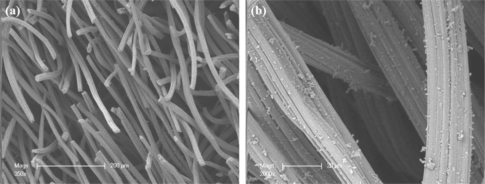
SEM images of the raw carbon felt material at a magnification of (a) 350× and (b) 2000×.
2.2 Aminoclay synthesis
The synthesis of aminoclays was carried out according to the protocol developed by Lee et al. [20]. The characteristics of the different reactants are gathered in Table 1.
Reactants used to prepare the aminoclays with different Fe/Mg ratios.
| Reactant | Purity (wt %) | Supplier |
| FeCl3·6H2O | 99.95 | Fluka |
| MgCl2·6H2O | 99.00 | Carlo Erba |
| Ethanol | 99.70 | Carlo Erba |
| C9H23NO3Si (APTES) | 98.00 | ABCR |
The synthesis procedure of aminoclays followed different steps. As an example, the synthesis of the aminoclay containing 100 wt % Fe (CA100) was achieved by the dissolution of 1.08 g of iron chloride hexahydrate in 20 mL ethanol, while stirring for 20 min at room temperature. Then 1.23 g of APTES was added dropwise to the solution. The stirring was maintained for 24 h. The solid was recovered by centrifugation, washed twice with ethanol (20 mL each time), and centrifuged again before being dried at 50 °C for 12 h. The same procedure was reproduced to prepare a series of aminoclay containing various Fe/Mg ratios (Table 2).
Mass ratios of Mg and Fe salts used for the different synthesis of the organic–inorganic hybrids and equivalent theoretical Si/Fe and Fe/Mg molar ratios.
| Reference | CA100 | CA50 | CA10 | CA0 |
| Mass ratio (total of 1.08 g each time) | ||||
| FeCl3·6H2O (wt %) | 100 | 50 | 10 | 0 |
| MgCl2·6H2O (wt %) | 0 | 50 | 90 | 100 |
| Molar ratio (theoretical) | ||||
| Fe/Mg | – | 0.75 | 0.065 | – |
| Si/Fe | 1.39 | 2.78 | 13.9 | – |
The theoretical Si/Mg or Si/Fe(II) ratio is 1.33 to obtain a TLH structure with a trioctahedral character. The silicon source (APTES) was always in excess in the synthesis process, because depending on the rate of Fe2+ or Fe3+ present in the octahedral sheet, the molar ratio could not exceed 1.33. If Fe3+ cations occupy all the octahedral sites of the TLH framework, then the maximal Si/Fe ratio could not be higher than 2.01. It means that for the CA100 TLH, the Si/Fe ratio must be between 1.33 and 2.01, if 100% of the engaged iron reacts to form the TLH.
The composite materials were prepared by adding similar square pieces of carbon felt (2 cm × 2 cm, width 0.6 cm (volume, 2.4 cm3)) in the solution used to form the different aminoclays. Carbon felt was added before or after the APTES. The samples were labeled CAx where x stands for the weight percent of FeCl3·6H2O introduced in the solution.
2.3 Characterization
X-ray diffraction (XRD) analyses were performed using a D8 Advance X-ray diffractometer with filtered Cu Kα radiation in the 2θ range from 2° to 70° at a scanning step of 0.017° on samples CA50 and CA100. The carbon felt material was also analyzed using a D8 Advance X-ray diffractometer with filtered Cu Kα radiation, but with 2θ range from 10° to 90° and a scanning step of 0.01°. The XRD analysis for CA10 and CA0 samples was carried out using a PanalyticalX’Pert PRO MPD X-ray diffractometer at a scanning step of 0.02° in a 2θ range from 2° to 70° with Cu Kα radiation. The data were treated with XPert Highscore software.
Fourier transformed infrared (FTIR) spectra were recorded using an infrared Raman spectrometer IFS 55 Bruker Optics, on powder-pressed KBr pellets. The pellets were prepared by mixing around 10 mg of sample with 100 mg of KBr powder and pressed using Herzog TP40 hydraulic press. The parameters used for pressing were 3 tons pressure for 3 min. The range of measurements was between 4000 and 400 cm−1, with 200 scans to lower the presence of noise in the spectra.
Elemental analyses were carried out by X-ray fluorescence using a MagicX Philips Fluorescence spectrometer (containing a PW 2540 VRC Sample Changer). A sample (200 mg) was pressed for 3 min under 4–5 tons by the same press used for the FTIR pellets, to form pellets.
The solid-state nuclear magnetic resonance (NMR) study was carried out using a Bruker Avance II 300 spectrometer (B0 = 7.1 T) at 59.6 MHz with a 7-mm diameter cylindrical rotor. The rotor was programmed at a spinning frequency of 4 kHz at a constant temperature of 293 K. The type of analysis performed was 29Si cross polarization magic angle spinning (CP-MAS) and magic angle spinning spectra with heteronuclear DECoupling (MAS+DEC) for quality and quantity analyses. The software used for treating the data was TopSpin and dmfit.
Scanning electron microscopy (SEM) analyses were performed on the composite samples using a Philips XL30 apparatus. As carbon is a good conductive material, the SEM observations were carried out without any coating. The carbon felt and the composite materials were pasted on the observation support with conductive carbon cement.
2.4 Electro-Fenton tests
The experimental setup used for current–potential curves and electro-Fenton process involved three electrodes: the composite material as the working electrode, a platinum counter electrode (32 cm2), and a saturated calomel electrode as a reference electrode (Fig. 2). The electrolytic solution (volume of 50 mL) was 0.05 M of Na2SO4 with 99% of purity (Thermo Fisher Scientific, Geel, Belgium) at pH = 3 and 30 °C. Before plotting the current–potential curves, the solution was saturated with N2 gas bubbling to eliminate the dissolved oxygen. Electrolysis tests were carried out at −0.5 V/saturated calomel electrode (SCE) in a monocompartment electrochemical cell (50 mL) in the same electrolytic solution as for plotting the current–potential curves. Compressed air was bubbled into the solution for 30 min before the electrolysis to saturate the solution with O2 and then continued throughout the experiments.
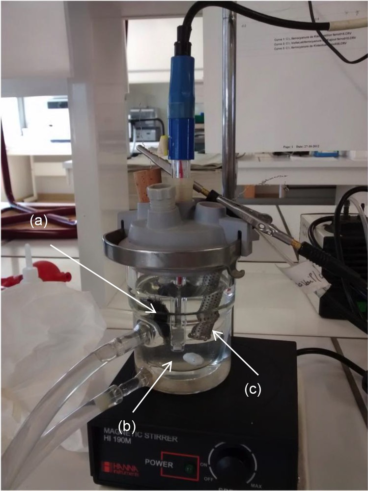
Experimental setup used for the current–potential curves and the electrolysis tests: (a) cathode (composite material or carbon felt alone), (b) reference electrode (saturated calomel electrode), and (c) counter electrode (Pt).
To study the performance of the composite in an electro-Fenton process, a tri-iodide compound, N,N'-bis(2,3-dihydroxypropyl)-5-(2-(hydroxymethyl) hydracrylamido)-2,4,6-triiodo-N,N′-dimethylisophthalamide (C20H28I3N3O9), was purchased from Sigma–Aldrich (99% of purity; Saint-Quentin Fallavier, France).
The three-electrode system was connected to a Potentiostat PGP 201 Voltalab (Radiometer Analytical, Villeurbanne, France) and monitored with VoltaMaster 4 Software.
3 Results and discussion
3.1 Morphological characterization of the composite materials
3.1.1 Addition of carbon felt before the APTES
The contact between the aminoclay solution and the material was direct, as the carbon felt was introduced directly into the synthesis solution before and/or after the addition of APTES. The purpose of such addition was to observe if there was any difference in the coverage of the carbon felt surface between the two methods. For sample CA100, when the carbon felt was added before the organic compound (Fig. 3), a full coverage of the fibers can be observed. The aminoclay layer seems to be homogeneous and thin at the surface of the carbon fibers (Fig. 3(a)). There is no discontinuous coverage and the fibers seem to be shielded all over by the aminoclay layer. Fig. 3(b) shows that even if the coating is homogeneous, there are still some small defaults in the coverage. The thin layer of aminoclay can be better observed at the end of the fibers, where the cut was produced. The thickness of the coverage with the aminoclay can be estimated to be close to 100 nm for the CA100 sample.

SEM images corresponding to sample CA100 observed at different magnifications (a) 500× and (b) 2500×.
SEM analysis performed on sample CA0 shows that the fibers of the porous bed of carbon are partially covered in an aminoclay-like structure. The fibers appear to be tangled in a nonhomogeneous and viscous mass of aminoclay. The coverage of the fibers appears to be random with a changing morphology. Some fibers seem to be covered by a thin layer of aminoclay, whereas others appear to be soaked in clay matter. Among them, there are some that are untouched by the aminoclay particles. In the coverage there are some round shaped aggregates, which are emerging from the aminoclay layer (Fig. 4(a)). By increasing the magnification, indeed, different size aggregates are observed on the fibers. Some clay agglomerates are present on the fibers, even in the absence of the aminoclay layer. This might suggest that these aggregates were formed first, attached to the fiber, and then the clay coverage started from the top. Around these rough surface agglomerates, the aminoclay forms in layers; thus, showing the preference for layered coverage. The smooth aminoclay surface also appears as a film, which captures the fibers at their crossing points. The morphology of such aggregates is alike, with a random spreading and with shapes of different size.
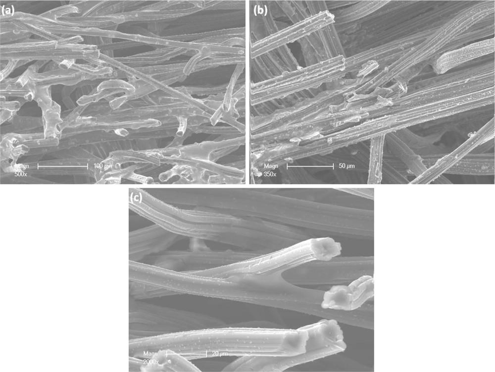
SEM images corresponding to samples CA0 (a), CA50 (b), and CA10 (c) observed at different magnifications (a) 500×, (b) 350× and (c) 2000×.
SEM images of sample CA50 show carbon fibers partially covered by an aminoclay layer. Some shortages can be observed in the coverage, which might be linked to the detachment of two or more fibers (Fig. 4(b)). At the edges of the coating layer, some small aggregates can be noticed, which might suggest a development of a second layer of coverage. In addition, at the edges of the coating layer, next to the small aggregates some very thin filaments appear to be detaching from the carbon fiber surface. This behavior might suggest exfoliation or a misfit in the adhesion of the aminoclay layer.
SEM analysis was also performed on CA10 sample. Results show that the porous carbon felt bed with the tangled fibers was covered by a very low amount of aminoclay (Fig. 4(c)). The aminoclay appears to be present between the fibers, at connection points, and in the neighborhood of other fibers. This might suggest that the clay formation has a preference for narrow spaces. There are also some small parts of the fibers with aminoclay on the surface. The aminoclay appearance in this case is of a smooth overpass or a smooth aggregate formed between two fibers. The consistency of the aminoclay coverage is uneven and nonhomogeneous. Despite the presence of such clay behavior, most of the fibers' surface appears not to be covered by the clay particles.
3.1.2 Addition of carbon felt after the APTES
SEM analysis was also carried out on the different composites prepared when carbon felt was added after the APTES silicon source. For the CA100 composite, the SEM analysis shows a partial coverage of the fibers of the porous carbon felt by a layer of clay (Fig. 5(a)). The coverage is uneven and nonhomogeneous. Cleavages can be observed along the thick portions of aminoclay, which suggests adhesion problems between the material and the clay particles or only between clay particles. However, the aminoclay thickness at which the cleavages are produced is debatable as more cleavages are observed along the thin clay coverage as well. Thus, there is no preferential behavior of the aminoclay cleavages. Considering this, the adhesiveness between the clay particles and the fibers is poor due to both interactions between aminoclay and material and between aminoclay particles. The coverage looks like an almost smooth uneven surface with ruffles at the border of the coverage portion. In conclusion, the aminoclay containing 100 wt % Fe incorporated by this way gives only a partial coverage of the carbon felt surface, with a nonhomogeneous and thin clay layer.
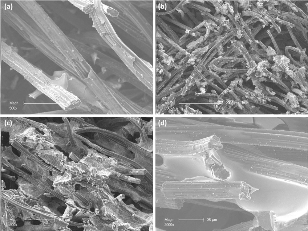
SEM images corresponding to samples CA100 (a), CA0 (b), CA50 (c), and CA10 (d) observed at different magnifications (a) 500×, (b) 350× (c) 500×, and (d) 2000×.
For composite CA0, the randomly spread clay aggregates are attached to the carbon fibers. The carbon felt bed still appear to be porous. The aminoclay aggregates appear to have different morphologies, as their shape and size are dissimilar (Fig. 5(b)) and are poorly attached to the fibers' surface. The fibers do not appear to have a smooth coverage but a rather rough one, as they are covered by aggregates of aminoclay.
By decreasing the amount of Fe salt to 50 wt % Fe (CA50), a different organization of the clay inside the carbon felt can be observed. The carbon fibers appear to be partially covered by blocks of aminoclay with irregular structures. In fact, some of the fibers appear to be breaking through the aminoclay blocks and some appear to be trapped inside (Fig. 5(c)). The surface of the blocks reflects both the Fe and Mg aminoclay structures as there is one unruffled surface (Mg) and the other fizzy (Fe). Some smooth surfaces might exist due to a detachment of the carbon fibers. The hollow spherule surface of the blocks, partially covering the carbon felt fibers, was also observed at higher magnification (not shown). The thickness of the aminoclay blocks is hard to evaluate. Although the fibers do not appear to be fully covered by a thin layer of clay, the fibers are still partially incorporated in blocks of aminoclay that give hardness to the carbon felt material.
The SEM analysis of the composite CA10 is shown in Fig. 5(d). It shows some aminoclay on the fibers as some parts of the fibers are tangled in a clay structure. The carbon bed still remains a porous material even after the synthesis. The aminoclay appears to be present between the fibers or in places that connect two or more fibers together. The clay appears as smooth area between the fibers, acting like a connecting bridge with an uneven thickness. Nonetheless, there are still some segments of fibers that show some partial coverage without other fibers involved.
To conclude, by adding the carbon felt after APTES, the formation of the clay inside the carbon felt is different, highlighting the influences of the synthesis protocol sequences. For the composite CA100, the aminoclay appears to be incorporated into the carbon felt bed, partially covering the fibers. Decreasing the amount of Fe to 50 wt % (CA50), the aminoclay appears to be forming big blocks, that incorporate the fibers or out of which the fibers cross them. The composite CA0 shows the formation of aggregates around the fibers, but with no good adhesion between the fibers and the aminoclay. In the presence of small amounts of Fe (CA10) the smooth clay appears to be present only at the cross-sections of the fibers. Consequently, it was decided to continue this study with the different composites prepared when carbon felt was added before APTES. This choice was guided by the necessity to obtain a thin and homogeneous layer of aminoclay at the surface of the carbon fibers to optimize the final properties of the composite material.
3.2 Structural analysis of the aminoclays obtained with different Fe/Mg ratios
The XRD analysis was performed to confirm the formation of the layered structure and the occupancy of the octahedral sheet. The XRD patterns of the samples are displayed in Fig. 6. The sequence of peaks observed in the diffractograms can be indexed as (001), (020, 110), (130, 220), and (060, 330) and are consistent with the formation of a TLH [9,19].
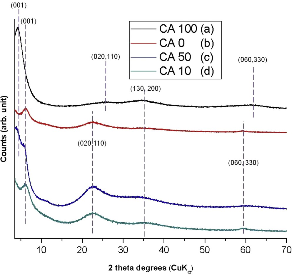
XRD patterns for samples with carbon felt and aminoclay with different Fe/Mg ratios: (a) CA100, (b) CA0, (c) CA50, and (d) CA10.
The values of the d001, which refer to the sum of the interlayer space and the layer thickness, are not the same as the one mentioned for the parent talc; a d001 value of 9.6 Å is observed for the parental talc [38,39], which implies that the difference between the d001 of the aminoclay and the d001 from the parental talc can be assigned to the interlayer space. The increase in the basal distance suggests the presence of organic moieties bonded to the inorganic layer inside the interlayer space [17]. The maximum chain length of aminopropyl chain calculated with the program ACD/ChemSketch is 5 Å, as reported [40].
The peak located at around 2θ = 60° corresponds to the reflection on the (060) plane. This latter gives indication on the dioctahedral or trioctahedral character of the structure. According to the literature, if the value is around 1.51 Å, the aminoclay has a dioctahedral character. If the value is close to 1.57 Å, then the aminoclay has a trioctahedral character [9].
The diffractograms of samples CA0 and CA10 (Fig. 6(b) and (d) respectively) show similar trends. They display a series of peaks corresponding to a TLH. For the CA0 sample (Fig. 6(b)) the following interlayer distances are observed: d001=13.57 Å, d020,110 = 3.94 Å, d130,220 = 2.50 Å, and d060,330 = 1.56 Å. This is in agreement with the related literature [41]. An increase of approximately 4 Å in the basal distance can be observed in comparison with the parental talc, which can be attributed to the presence of the organic chain bonded to the inorganic layer, inside the interlayer space [20]. For the CA10 sample (Fig. 6(d)) the calculated d001 value is 14.40 Å, suggesting that the interlayer space value is 5 Å, the same value as the one calculated for the organic chain length. Thus, the arrangement of the organic chains in the interlayer is an interlocking monolayer of APTES groups. The d060 value of 1.55 Å is a statement of the trioctahedral character of this sample.
In the case of the sample CA100, the XRD pattern shows a series of peaks corresponding to a 2:1 phyllosilicate with a TLH and a dioctahedral character (d060=1.51 Å) (Fig. 6(a)). It presents a pseudo-trimolecular layer of APTES in the interlayer space (d001=21.5 Å).
Sample CA50 (Fig. 6(c)) presents also a 2:1 phyllosilicate structure but with a rather different character as the interlayers form a mixture of mono and pseudo-trimolecular layers of organic moieties (d001 appears both at 21.9 and 15.4 Å). This may be because carbon felt can have an impact on the organic moieties settlement in the interlayer of the aminoclay. As the (060) reflection is broad it is difficult to deduce a d060 value.
As compared with the parental talc material, the reflections of the different XRD patterns obtained with the aminoclays appear to be broad, which suggests a lower organization of the synthesized aminoclays. This phenomenon can be regarded as an evidence for the presence of the organic chains in the structure as already mentioned in the literature [13,40,41].
Solid-state NMR analysis was performed to give additional information for the formation of the aminoclays. There are three different environments that can be observed when organoalkoxysilanes are used as a silicon source. The notation is Tn and represents the RSi(OM)(OSi)n−1(OH) species, where n refers to the number of siloxane bonds (SiO), R represents the organic part bonded to the silicon atom through silicon–carbon bond, and M refers to the octahedral metallic ion [41]. A high amount of Fe in the sample prevents carrying out NMR experiments; hence, only CA0 and CA10 samples were analyzed (Fig. 7(a) and (b) respectively). In CP-MAS NMR analysis, both samples appeared to be characterized by the presence of T1 (−49 ppm), T2 (−58 ppm), and T3 (−67 ppm) units. The main peak corresponds to the T3 environment, which suggests a high degree of condensation of the silicon species.

29Si CP-MAS NMR spectra of samples (a) CA0 and (b) CA10.
3.3 Elemental analysis of the aminoclays obtained with different Fe/Mg ratios
The chemical composition of the different aminoclay samples with carbon felt fibers was obtained using the X-ray fluorescence analysis. The results are shown in Table 3. The results for the experimental molar ratio are consistent with the theoretical values expected for CA50, CA10, and CA0 samples. The Fe/Mg ratio of the CA50 sample (2.59) is higher than the theoretical value. This may be explained by the presence of Fe3+ in the octahedral sheet rather than Fe2+, which creates a vacancy of one octahedral site for two Fe3+ (to respect the charge neutrality). Then each vacancy can be attributed to the absence of a Mg2+ cation, and then to a higher Fe/Mg ratio.
Si/Fe and Si/Mg molar ratios of aminoclays prepared in the presence of carbon felt.
| Sample reference | Molar ratio | ||
| Ratio | Theoretical | Experimental | |
| CA100 | Si/Fe | 1.39 | 0.30 |
| CA50 | Si/Fe | 2.78 | 2.50 |
| Fe/Mg | 0.75 | 2.59 | |
| CA10 | Si/Fe | 13.90 | 10.81 |
| Fe/Mg | 0.08 | 0.12 | |
| CA0 | Si/Mg | 1.04 | 1.20 |
In the case of the CA100 sample, the Si/Fe ratio is lower than the expected value (0.30 as compared with 1.39). This suggests that a great part of the Fe does not react in the system to form other phases.
FTIR analysis performed on all the aminoclays in contact with carbon felt shows no difference from the FTIR results obtained for the samples containing only aminoclay. The characteristic bands corresponding to the clay structure along with the bands that confirm the presence of the organic moieties bonded to the inorganic framework can be observed in the spectra presented in Fig. 8. The characteristic stretching and bending vibrational bands are reported in Table 4.

FTIR spectra of the different solid residues obtained during the synthesis of the different composite materials (a) CA100, (b) CA0, (c) CA50, and (d) CA10.
Stretching and bending vibrational bands (cm−1) observed on the different IR spectra obtained with the aminoclays.
| Sample | Stretching and bending vibrational bands (cm−1) | ||||||||||
| OH | CH2 | NH3 | NH2 | CH2 | SiOH | SiOSi | CN | M–O | SiC | M–OSi | |
| CA100 | 3368 | 3049 | 1973 | 1603 | 1492 | 1034 | 1094 | 939 | 472 | 1220 | 693 |
| CA0 | 3413 | 3041 | 1976 | 1606 | 1495 | 1034 | 1030 | 935 | 568/406 | 1137 | 699 |
| CA50 | 3369 | 3037 | 1974 | 1603 | 1490 | 1033 | 1042 | 939 | 694/472 | 1226 | 690 |
| CA10 | 3414 | 3035 | 1993 | 1608 | 1495 | 1034 | 1094 | 939 | 569/471 | 1220 | 697 |
For the CA100 composite, the typical vibrations of the organic functional groups are shown in Fig. 8(a). The stretching band corresponding to FeOH groups can be observed at ∼3368 cm−1 and refers to the stretching vibration of OH groups in the absorbed water and silanol groups [42]. Along with it, the stretching and deformation vibration of CH2 can be also noticed at ∼3049 and ∼1492 cm−1, respectively. At ∼1973 cm−1 the band for ammonium (NH3+) could be observed due to the protonation of NH2 (bending vibration at around ∼1603 cm−1). Other important bands are SiC (∼1220 cm−1), SiOSi (∼1094 cm−1), SiOH (∼1034 cm−1), and CN (∼939 cm−1).
The typical SiC bond evidences the integrity of the organic moieties during the formation of the inorganic framework [43]. For the typical metal present in the structure, the band at ∼693 cm−1 corresponds to the deformation of the FeOSi. The FeO band registered at 472 cm−1 could refer to the stretching vibration of the organophyllosilicate octahedral sheet [19].
The FTIR analysis performed on CA0 sample (Fig. 8(b)) evidences the presence of all the vibration bands expected for aminoclays. The OH stretching band can be observed (∼3413 cm−1) along with CH2 stretching (∼3041 cm−1), NH3+ (∼1976 cm−1), NH2 (∼1606 cm−1), CH2 (∼1495 cm−1), SiC (∼1137 cm−1), SiOSi (∼1030 cm−1), SiOH (∼1034 cm−1), CN (∼935 cm−1), and MgOSi (∼699 cm−1).
In the case of sample CA50 (Fig. 8(c)), a SiOC (∼1115 cm−1) vibration is present beside the characteristic aminoclay vibration bands suggesting that the APTES is not fully hydrolyzed and condensed. For this sample and for CA10, it is hard to attribute the M-O vibration band to either Fe or Mg as some sources quote MgO at ∼559/470 cm−1 [44] and FeO at ∼690/447 cm−1 [19]. Thus, it cannot be exactly presumed which band can be attributed to MgO vibration and which one to FeO vibration in the case of a mixture, because the literature [19,45] does not give more than an approximate range for a generic M-O vibration band. Subsequently, for the different metals present in the structure of the aminoclay containing 50 wt % Fe, it can be observed that the sample has a FeO band at ∼694 cm−1 along with a band MgO at ∼472 cm−1. For the aminoclay containing 10 wt % Fe, the metallic bond M-O at ∼697 cm−1 can be attributed to FeO and at ∼569/471 cm−1 to both FeO and MgO as there is no possibility to precisely determine which one is.
To summarize, the formation of organic–inorganic hybrids was evidenced in the presence of carbon fibers in the synthesis solution. Depending on the way the carbon felt was added to the solution and on the iron content, it is possible to obtain a thin and quite homogeneous film of aminoclay at the surface of the carbon fibers to obtain a composite material (CA100). This result enables the use of this composite as a cathode electrode in the electro-Fenton process o replace the classic system usually encountered (carbon felt + Fe2+ in the treated solution). To validate the concept of this new kind of electrode and its suitability for the electro-Fenton process, it is necessary to verify the conductive properties of the material (to compare with pure carbon felt) and also to estimate the electrolysis performance that can be reached with this composite material.
3.4 Electrochemical studies
First, current–potential curves were plotted to estimate the conductive properties of the composite material (CA100) in the supporting electrolyte (Fig. 9). Even in the presence of a thin and continuous layer of aminoclay, the composite remained conductive but more resistive than carbon felt alone. Water oxidation and water reduction behaviors were similar for the two working electrodes.
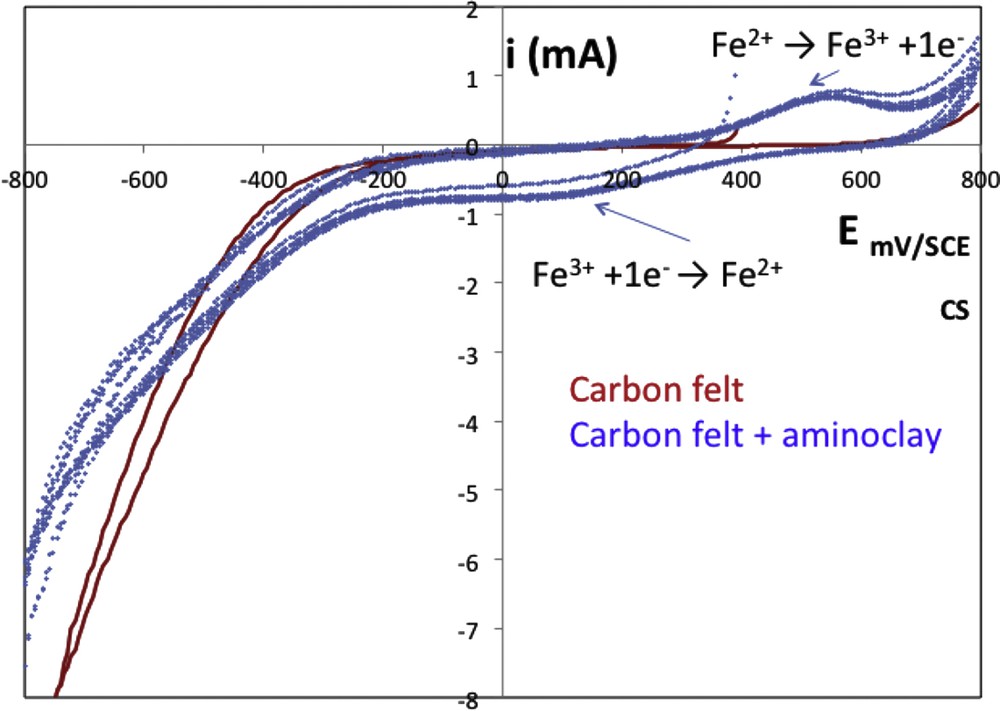
Current–potential plot of the composite material in 0.05 M Na2SO4 supporting electrolyte, at pH = 3 under inert atmosphere (N2) and 30 °C, obtained with graphite felt (continuous line) or CA100 composite (dashed line) as working electrode, Pt counter electrode, and saturated calomel electrode with a scan rate of 10 mV s−1. SCE, saturated calomel electrode.
Current–potential curves were first plotted toward reduction potentials up to −0.8 V/SCE and with the composite working electrode, a supplementary signal was observed around 0.1 V/SCE. This signal corresponded to the reduction of immobilized Fe(III) into the composite (Eq. 1).
| (1) |
During the feedback scan, a signal around 0.55 V/SCE corresponding to the produced Fe(II) oxidation was noted.
When voltammogram was first plotted toward oxidation potentials, no signal was observed around 0.55 V/SCE unlike signal around 0.1 V/SCE (data not shown). This means that iron was present in the CA100 composite as Fe(III) and this result was in accordance with those obtained in Section 3.3.
Moreover, composite CA100 can be considered as a stable working electrode because after 20 cycles, voltammograms were reproducible.
Taking into account the electrochemical positive reply of the carbon felt material with aminoclay containing 100 wt % Fe (CA100) as an electrode material, it was further tested during electrolysis.
Preliminary electrolysis was performed with graphite felt and composite CA100 electrode with the objective to degrade the tri-iodide model molecule. After 4 h of electrolysis, 70.5% of the tri-iodide organic compound was degraded with graphite felt. Because no ferrous ions were added in the electrolytic solution, the degradation of the organic compound can be due to its direct electrochemical reaction at the graphite felt surface or its reaction with hydrogen peroxide produced from the oxygen electrochemical reduction (Eq. 2).
| (2) |
With the modified carbon felt, degradation yield reached 98%. The presence of iron in the electrode material could explain the better degradation. Indeed, as the electrode was negatively polarized, Fe(III) inside the composite was reduced to Fe(II), which could further react with the produced hydrogen peroxide to form hydroxyl radicals (Eq. 3). These hydroxyl radicals can then oxidize the tri-iodide organic compound.
| (3) |
In these operations, supplementary hydroxyl radical production can explain the better degradation yield.
Owing to these interesting results regarding the degradation of the tri-iodide compound and to confirm the potential of this composite as a working electrode, further studies are needed to investigate its mineralization and the stability of the composite electrode.
4 Conclusions
The development of a new system to treat persistent organic pollutants was investigated in this study. The originality of the present study lies in the immobilization of iron used as a catalyst for the electro-Fenton process directly onto the cathode, instead of its use in solution as it is usually the case. For this, a composite material was prepared with carbon felt and aminoclay containing iron. The aminoclay was characterized and it corresponds to an organic–inorganic hybrid with a TLH that may present a dioctahedral or a trioctahedral character depending on the Fe/Mg ratio. The preparation of the composite material was optimized through a series of experiments. The thickness of the aminoclay layer was estimated to be close to 100 nm for the best composite material, containing 100 wt % Fe. This material is conductive and presents interesting performances for the degradation of the model organic compound, a tri-iodide compound. These first results are encouraging; consequently, further investigations are needed to estimate the lifetime of the material (an aging study), as well as the analysis of the decomposition products. At the moment, the concept proof has been achieved; a scale up of the process has to be done in the future.
Acknowledgments
This study was funded by the Material Science Institute of Mulhouse (IS2M) in the frame of “call to emerging project” and performed in collaboration with the Chemical Science Institute of Rennes (ISCR).