


 CC-BY 4.0
1. Introduction
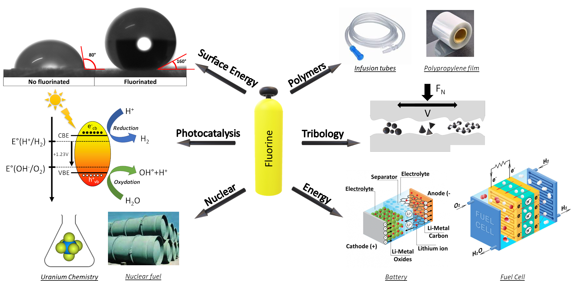
Inorganic fluorine chemistry applied to materials requires an interdisciplinary approach that integrates chemistry, materials science, and engineering, fostering a collaborative environment that pushes the boundaries of what is possible with fluorinated materials. The potential applications of the fluorination technologies are vast. Selected examples include photocatalysis, where fluorinated materials improve the efficiency and stability of photocatalysts, offering new solutions for environmental remediation and energy conversion. In fuel cells, improved catalytic activity and corrosion resistance of fluorinated catalysts contribute to more efficient and durable fuel cells. Fluorination also provides robust protective coatings for metals and alloys, extending their service life in harsh environments. In healthcare, fluorinated biomaterials and polymers are being developed for medical devices and drug delivery systems, exploiting the unique properties of fluorine to improve performance and biocompatibility. Fluorine chemistry also plays a critical role in nuclear applications, where fluorinated materials are used to develop high-performance coatings and components that can withstand extreme conditions. This includes the production of fuels that are essential to the safety and efficiency of nuclear reactors and other related technologies.
The Clermont-Ferrand Institute of Chemistry (ICCF) is at the forefront of research into fluorination processes and the development of fluorinated materials, exploiting the unique reactivity of fluorine to innovate in a wide range of applications. The Institute’s thematic focus on fluorination encompasses a variety of methodologies, ranging from gas–solid interactions to solution-based processes, each tailored to address the specific challenges and requirements of different material targets. A common method is gas–solid fluorination, in which the material is exposed to fluorine gas or a fluorine-containing gas mixture at temperatures ranging from room temperature to 650 °C. This gas–solid interaction is very versatile and can be used either in the bulk or on the surface only. In the latter case, this route facilitates the incorporation of fluorine atoms onto the material surface, providing a uniform fluorine coating and is particularly effective for materials with high surface areas. Extending fluorination to the bulk poses several challenges: tailoring the fluorine content, the competition with decomposition due to the reactivity of most of fluorine species, the sublimation of the fluoride. The fluorine group at ICCF has developed advanced techniques to control the fluorination process at the molecular level, ensuring uniform and controlled fluorine incorporation.
The Institute has pioneered the development and application of a variety of fluorinating agents, each selected based on the specific material target and desired outcome. Key agents include elemental fluorine (F2), the most reactive form of fluorine, used for high-intensity fluorination processes; hydrofluoric acid (HF), commonly used for solution-based fluorination, particularly effective for etching and surface treatments; and fluorine-containing compounds such as xenon difluoride (XeF2) and terbium tetrafluoride (TbF4), which provide controlled fluorination environments for specific applications. The case of the fluorination of high surface area carbons perfectly illustrates the difficulties and how to overcome them; a recent paper [1] has reviewed such a case. Fluorinated (nano)carbons have been studied at ICCF for more than 40 years.
Research at ICCF focuses on a wide range of materials, each of which benefits uniquely from fluorination. Some targeted applications include electrode materials for batteries, where surface fluorination of electrodes has been shown to improve electrochemical stability, ionic conductivity, and energy density, significantly enhancing battery performance. Bulk fluorination processes are used to improve the structural integrity and electrochemical performance of cathode materials for lithium-ion batteries. In addition, the Institute is developing high-performance fluorinated carbons for use as advanced lubricants, offering superior performance and durability. Surface fluorination of polymers enhances their liquid-repellent properties and can facilitate the diffusion of plasticizers to the surface, improving material performance in various applications. ICCF is unique in its ability to precisely control fluorination processes at both laboratory and micropilot scale. This versatility allows research results to be transferred from the laboratory to potential industrial applications, ensuring that innovations can be effectively scaled up.
At the beginning of the timeline, simpler methods such as direct fluorination with F2 predominated. As research progressed, more sophisticated techniques emerged. For example, fluorination by anhydrous HF gained attention for its effectiveness in controlled environments. Catalytic fluorination introduced new efficiency by using catalysts to facilitate the fluorination process. Plasma fluorination gained prominence for its ability to achieve high reactivity at lower temperatures. Other advances included fluorination by the decomposition of solid fluorinating agents and by the decomposition of fluorinated polymers, each offering unique advantages in specific applications. Laser or plasma torch-assisted fluorination was another leap forward, offering precise control of the fluorination process and allowing targeted modification of materials. Each boxed figure in the graph corresponds to a breakthrough or increased research activity in the development of these advanced methods. The steady increase in the number of fluorination methods indicates growing interest and improvements in the control of fluorine incorporation into various materials, reflecting the increasing complexity and precision of fluorination techniques over the years. This trend underlines the importance of fluorination in material science and its expanding applications in various fields (Scheme 1).
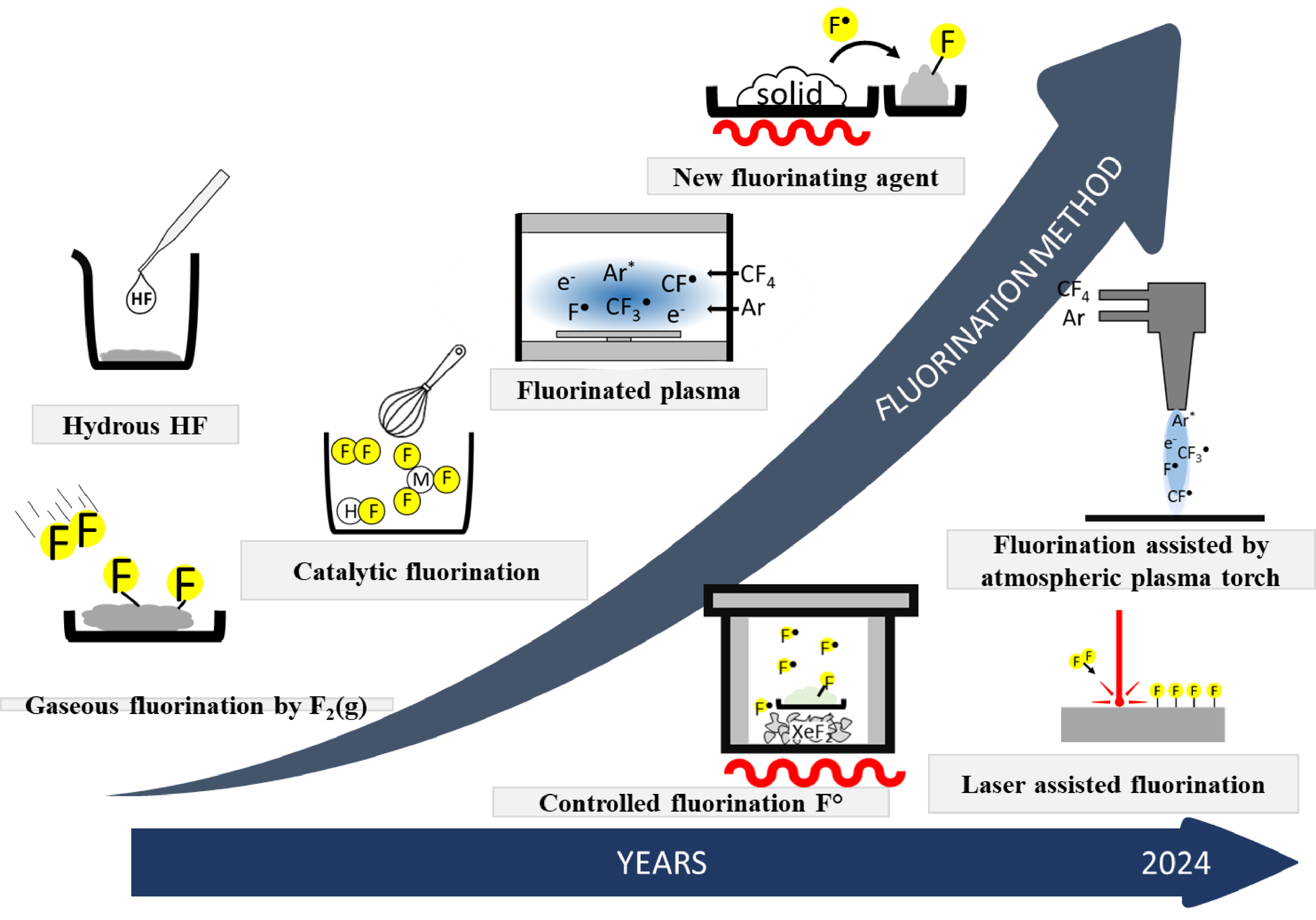
Evolution of fluorination methods at ICCF upon time.
In this paper, a few examples have been chosen to illustrate the diversity of applications and methods. The aim is not to be exhaustive. Firstly, applications that require the presence of fluorine on the surface will be discussed.
2. Surface engineering
2.1. Control of surface energy by fluorination
In many applications, such as the production of high-performance filler–matrix composites or hydrophobic surfaces, control of the interface between the various interacting components is critical. Modification of surface chemistry plays an important role in ensuring properties (mechanical, thermal, controlled ageing, etc.) where parameters such as adhesion or wettability are dominant.
This is particularly true in the field of composites, where the filler–matrix interaction is a key parameter to control. Carbon fiber–polymer composites are sensitive to moisture, which can lead to a deterioration in mechanical performance. One solution to this problem has been to carry out gas fluorination treatments on carbon fibers [2, 3] (which are generally coated with a thin layer of polymers to ensure their compatibility with the polymer matrix) to reinforce their hydrophobic character and limit water absorption. By modifying fluorination temperatures, it is possible either to perfluorinate the polymer-coated layer on the surface of the carbon fiber, or to eliminate the polymer and fluorinate the fiber surface directly (Figure 1a). This reactivity modularity makes it possible to adjust the reaction conditions in such a way that the mechanical properties of the original fiber are maintained, while the surface energy of the fiber is significantly reduced, making it more hydrophobic, but also more easily compatible with the polymer matrix.
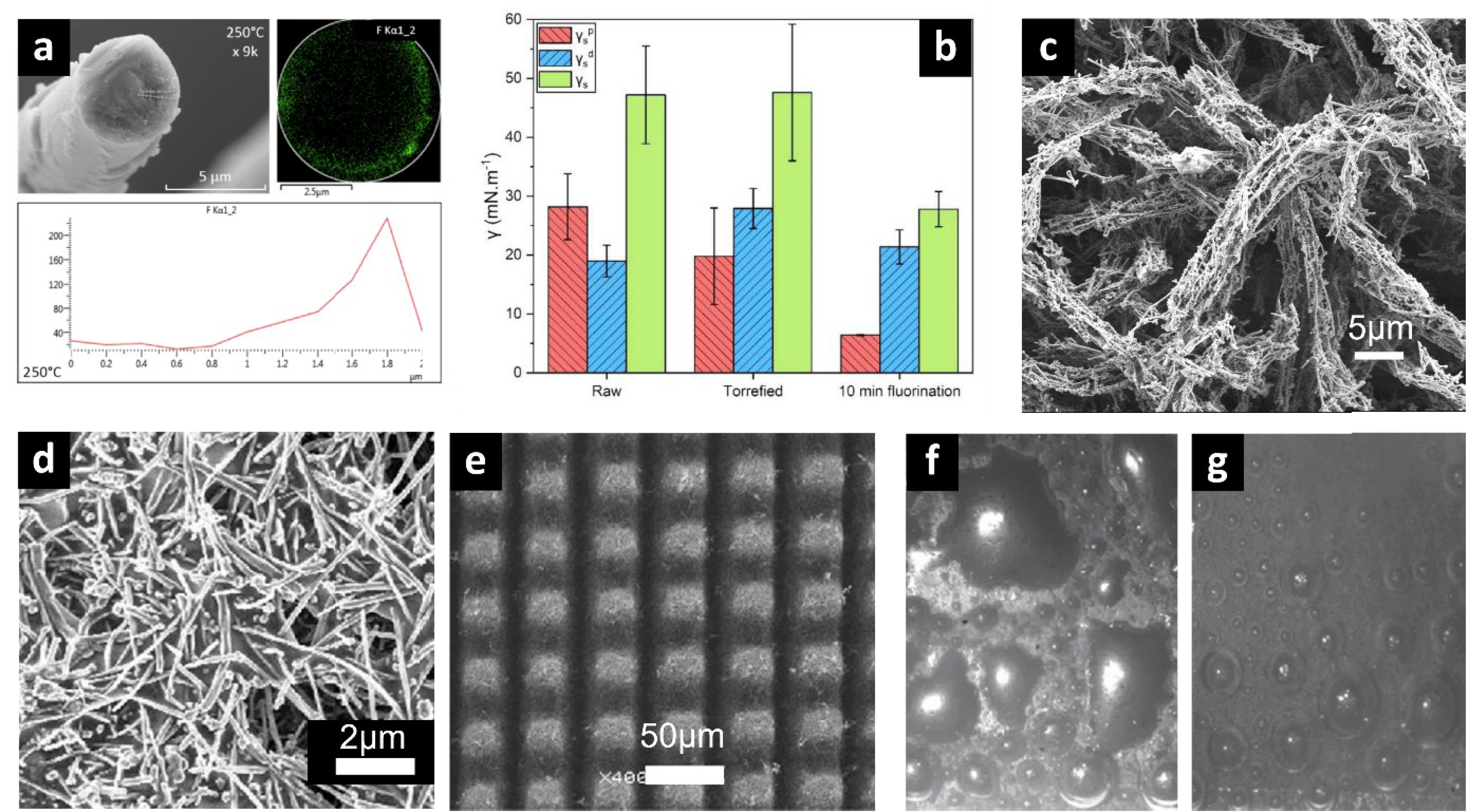
(a) Transversal section of carbon fiber fluorinated at 250 °C by F2(g) correlated with the EDX fluorine repartition from the core to the surface of the fiber; (b) Flax fiber fluorination treatment effects on polar, dispersive and total surface energy; (c) Fluorinated electrospun PVP/fluorinated carbon nanofibers composite; (d) F-CNF/PS nanocomposite; (e) Laser microtextured F-CNF/PVDF nanocomposite; Anode images ((f) raw and (g) microtextured) during electrolysis of fluorine in KF-2HF.
The latter aspect has also been extensively studied by our group in the case of eco-composites, using flax fibers as reinforcing fillers. One of the main drawbacks of flax fibers in this application is their surface chemistry, rich in oxygenated groups, which induces a polar surface character that limits their compatibility with the matrix polymers commonly used. By grafting fluorinated groups (either by fluorine plasma treatment [4] or by direct fluorination [5]) directly onto the surface of the fibers (thereby significantly reducing the polar component of the surface energy), it has been possible to significantly reduce the overall surface energy of natural fibers (Figure 1b), making them more hydrophobic and compatible with the polymer resins, while maintaining their good mechanical properties [6].
One of the major advantages of direct fluorination is its ability to homogeneously treat surfaces with complex geometries. This has been applied to electrospun nanocomposites based on polyvinylpyrrolidone (PVP) microfibers doped with fluorinated nanocarbons [7]. By finely modulating the reactivity of molecular fluorine with the polymer matrix, it is possible to control the competition that exists between the perfluorination of the polymer in the solid state and its degradation into volatile fluorocarbons inducing the etching of the latter. This has enabled us to create a high-performance superhydrophobic coating with multi-texturing at the micro- and nanoscale (Figure 1c).
This approach has also been used to prepare superhydrophobic films based on fluorinated polymers such as polyvinylidene fluoride (PVDF), or poly(ethylene oxide) (PEO) fluorinated with F2, as well as commercial hydrophobic polymers such as polystyrene (PS), which have been used as a binder and/or polymer matrix to prepare nanocomposites [8]. Stable superhydrophobic properties are obtained with fluorinated carbon nanofibers (F-CNF)/PVDF nanocomposites microtextured by femtosecond laser ablation and F-CNF/PS nanocomposites, with water contact angles of 157° and 155°, respectively (Figures 1e and 1d).
Our group’s expertise in controlling the reactivity of molecular fluorine has also enabled us to develop a new approach for its preparation by electrolysis in KF-2HF medium. By controlling the microtexture of the carbon anode surface using a femtosecond laser ablation method, it is possible to radically alter the interaction of the electrogenerated fluorine bubbles with the carbon surface [9]. Whereas on conventional anodes the fluorine bubbles tend to spread out on the surface (Figure 1f), thus limiting the electrolysis performance, our approach allows the generation of spherical bubbles that quickly detach from the surface (Figure 1g), thus significantly increasing the gas production and limiting the anode ageing (by reducing the formation of fluorinated carbons on the surface due to a shorter contact time of the molecular fluorine with the carbon).
2.2. Surface fluorination of polymers and its benefit to medical devices
Many medical devices (MDs) made of PVC, especially disposable ones, are used extensively in healthcare facilities every day. Indeed, PVC offers durability, chemical resistance, and low replacement costs. The addition of a plasticizer, usually of the ester type, gives PVC the necessary flexibility, durability, and reliability. Plasticization also gives tubular-type devices the transparency needed to monitor the flow of drugs or biological fluids. Plasticized PVC is therefore widely accepted for use in various flexible medical devices (bags, catheters, and gloves) and especially for tubing (infusion/transfusion lines, pump tubing, and extenders). A major drawback for medical use is the diffusion of chemicals present in the polymer matrix towards solution in contact with it. As they are not covalently bonded to the polymer chains, plasticizers can therefore be partially extracted by certain fluids, resulting in patient contamination by fluids (drugs, blood, gas, etc.) circulating in medical tubing. Some plasticizers are therefore potentially harmful and are recognized as endocrine disrupters, carcinogens, mutagens, or substances toxic to reproduction or certain organs. In the following, we will describe, by means of an example, how the chemical surface modification with fluorine of a MD made of plasticized PVC is an innovative solution to minimize such migration problems by creating a barrier between the plasticizer and the fluids in contact with it.
Surface fluorination of a polymer is a quasi-irreversible treatment because the grafted fluorinated chains are covalently bonded to the surface, ensuring long-term chemical stability. Direct fluorination at low temperatures has proven to be a very advantageous chemical method for tuning the physicochemical properties of a wide range of polymers [7, 10]. By controlled diffusion of fluorine, it is possible to modify only the external surface properties of the material, without affecting its intrinsic properties. The fluorinated layer generally exhibits a gradient consisting of a gradually decreasing fluorine content, a transition zone where the concentration of fluorinated functions decreases sharply, down to the unmodified polymer bulk. Fluorination is a heterogeneous reaction between the gaseous molecular F2 and the solid surface of the material, which requires no initiation step and can proceed spontaneously at room temperature. It is a dry, solvent-free process that can be applied to polymer objects of any shape, which is of industrial interest. Several studies have shown the advantage of the surface fluorination of various polymers for applications [11, 12]. In particular, the latter allows the creation of a barrier to permeation. In fact, fluorination induces a reduction in the free volume due to the H/F atomic substitution and, consequently, the permeability of fluorinated polymers is reduced. Direct fluorination proceeds via a radical mechanism that can induce inter/intra cross-linking as a side reaction. Such a surface effect inhibits potential solvation/swelling effects, thereby reducing permeability. Finally, the surface energy of fluoropolymers increases, reducing the chemical compatibility of low-polarity organic liquids with a fluoropolymer layer, which in turn reduces permeability. The diffusion of compounds through a fluorinated surface can therefore be significantly reduced.
The fluorination of PVC tubular MDs, containing esters as plasticizers, was carried out [13] at room temperature with pure molecular fluorine, in a closed reactor under a fixed amount of excess gas, at a pressure of 200 mbar and for 30 minutes. This static mode is preferred when a controlled and homogeneous fluorination of the sample is desired. Complementary physicochemical measurements (FTIR, XPS, 19F NMR, SEM, AFM) were carried out at different scales, in order to finely characterize the fluorinated layer formed. The most probable conclusions and hypotheses drawn from the former set of characterizations were that fluorination led to the formation of CHF, CF2, and CF3 groups, with an average fluorination rate of the fluorinated units close to 1.5 F per C, both throughout the fluorinated thickness (NMR) and at the outermost surface (XPS). They showed the prevalence of the –CF2–CH2– sequence on the surface (XPS C1s and F1s), the persistence of the ester groups despite fluorination, and a partial chemical modification in the vicinity of the ester groups of the plasticizers according to (i) fluorination in the α or β position (e.g., –CF2–COO) and/or formation of the anhydride group, both in the bulk (IR) and at the outermost surface (XPS O1s). (ii) Down chain fluorination (e.g., O=C–O–CF2–) at the outermost surface (XPS C1s and O1s). SEM images revealed etching of the tube surface caused by fluorination, despite the relatively mild conditions used. Indeed, the strong oxidizing power of molecular fluorine is known to induce chemical scissoring of alkyl chains through the hyperfluorination mechanism, resulting in the elimination of volatile short-chain fluorinated species (CF4, C2F6…) and in a subsequent material loss. Elemental mapping by EDX microanalysis carried out on cross-section of tubings showed that the thickness of a fluorinated layer was in the order of a few microns. The significant increase in the surface roughness of the surface of the treated MDs was quantified by AFM. Tensile tests showed that Young’s modulus of the tubes remained constant, the fluorinated thickness being negligible compared to the total wall thickness. Therefore, the mechanical and transparency properties were not altered after fluorination.
Figure 2 clearly illustrates, through a single example, the effective anti-diffusion barrier obtained from a treated MD, with respect to a plasticizer. The migration flux was compared with that observed from the same non-fluorinated tube. Migration was evaluated in a dynamic model (syringe pump) to approximate conditions as close as possible to clinical practice. A simulant (ethanol/water mixture 50% by volume) mimicking a lipophilic (i.e., most extractive) drug solution was infused through the tubes. After fluorination, the amount of plasticizer released in the simulant appeared to decrease sharply. The results obtained demonstrate that fluorination can be an effective method of preventing the release of plasticizers from plasticized PVC MDs already on the market.
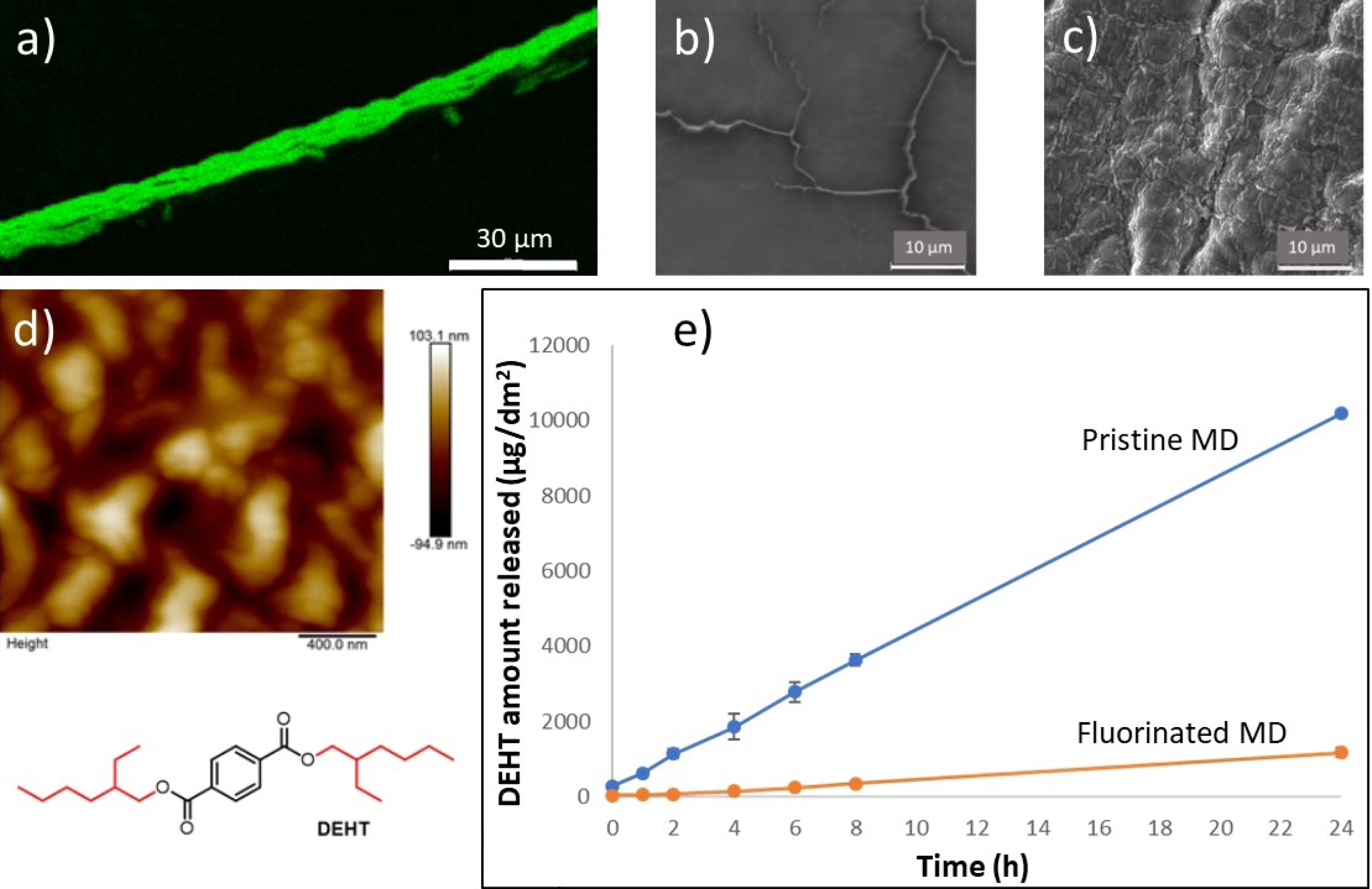
(a) Elemental fluorine mapping at the inner surface of a fluorine-treated PVC medical tubing, as seen by EDX. (b,c) SEM views (×2500) of the surface before and after fluorination, respectively. (d) Roughness of the fluorinated surface measured by AFM. (e) Quantification of plasticizer migration in dynamic mode.
2.3. Fluorinated (nano)carbons as solid lubricants
The covalent intercalation of fluorine atoms into graphitized materials with an F/C molar ratio higher than 0.15 reduces the coefficient of friction (CoF). The latter, shown in Figure 3, can be compared and discussed here because they are obtained under strictly with the same conditions using a ball-on-plane reciprocal tribometer consisting of an AISI 52100 steel ball rubbing against an AISI 52100 steel plane. The experimental details (surface preparation, solid lubricant deposition, sliding speed, a normal applied load of 10 N, burnishing method with the possible addition of pentane droplets to enhance tribofilm formation, mean contact pressure of 0.65 GPa according to Hertz theory) are given in references [14, 15, 16, 17, 18, 19, 20]. The benefits of the presence of F atoms on the intrinsic CoF (without pentane) are higher when considering carbonaceous nanomaterials are considered [15, 16, 17, 18, 20]. CoF ranging between 0.065 and 0.085 are achieved for carbon nanofibers (CNFs) and graphitized carbon blacks (GCBs), which are weaker than those of graphite (CoF of 0.18) and most other solid lubricants. An influence of the shape factor of fluorinated nanocarbons on the tribological properties has been observed [15, 16, 18]. Spherical particles such as GCBs have a slightly lower CoF, e.g., 0.065 and 0.07 respectively for F/C = 0.65 [15, 16, 18]. The difference could occur during the formation of a denser tribofilm due to the easy disaggregation of the spherical shape for carbon blacks compared to tubular carbon nanofibers [15]. At a similar fluorination rate, the CoF of micrometric graphite fluoride (GF) is higher, e.g., for the case of F/C = 1, values of 0.08 and 0.07 were recorded for GF and fluorinated GCBs (Figure 3a). The good tribological properties of fluorinated nanocarbons make them very promising as precursors for the tribo-active phase in lubrication.
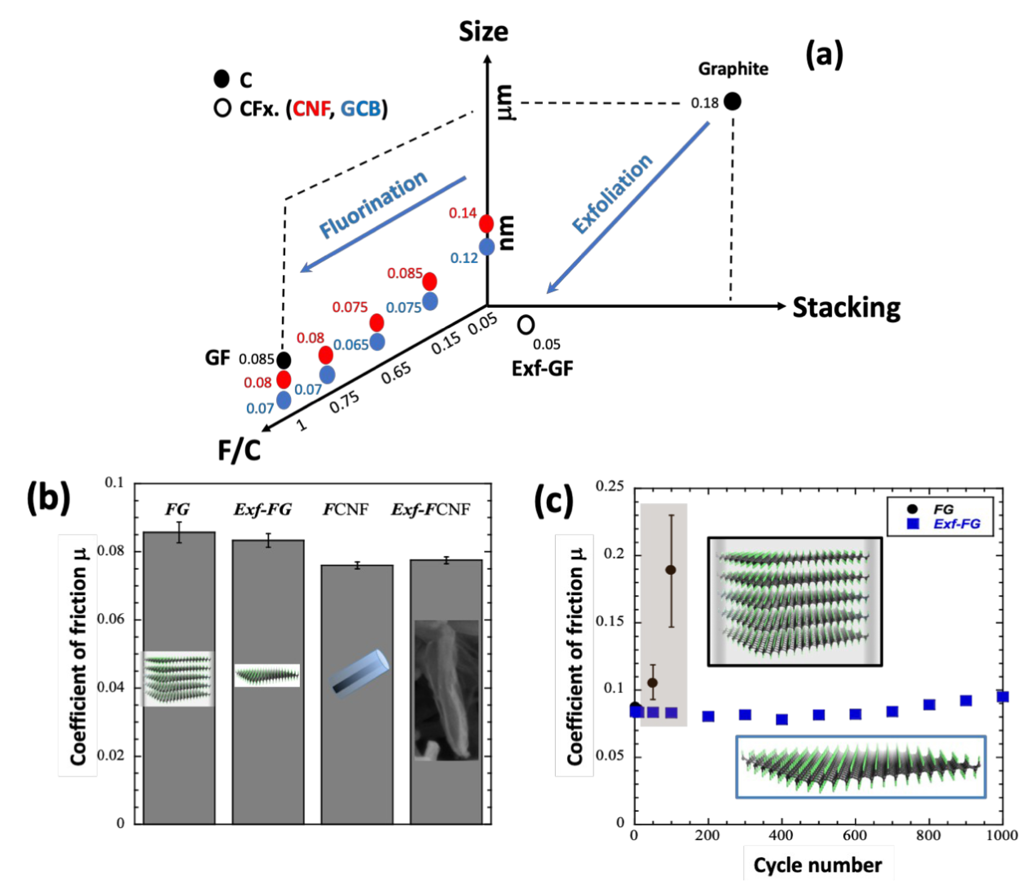
(a) Coefficients of friction for raw and fluorinated graphite (FG), carbon nanofibers (CNF and F-CNF), graphitized carbon blacks (GCB) and exfoliated graphite (Exf-FG). (b) Intrinsic CoF of raw and exfoliated fluorinated carbons (fluorinated graphite FG and fluorinated nanofibers CNFs) and (c) changes with the cycle number for raw and exfoliated FG.
Another strategy is to use fluorinated graphitized carbons as precursors for the preparation of multilayer graphene by exfoliation using a thermal shock (Figure 3b). Exfoliation and defluorination occur simultaneously resulting in compounds with low fluorine content, F/C close to 0.05 [17]. The preparation method can be applied to various fluorinated precursors, covalent graphite fluorides and fluorinated CNFs. Figures 3b and 3c show the data obtained with fluorinated graphite (FG) and fluorinated graphitized nanofibers. Despite the massive defluorination, the exfoliation did not degrade the excellent lubricating performance due to the weakening of the interparticle interactions within the exfoliated samples. Moreover, the exfoliated structure may facilitate the formation of a homogeneous and stable tribofilm, as discussed above for other fluorocarbons. Low CoFs (0.05) were then obtained from the first friction cycle, in contrast to the raw FG (Figure 3c). This section demonstrates the potential of fluorinated (nano)carbons as solid lubricants, taking into account the diversity of the allotropic forms, sizes and shapes of the carbonaceous starting materials. In addition, the C–F bond can be tailored from ionic to covalent, both to further reduce the coefficient and friction and to favor high quality and denser tribofilms [19].
2.4. Surface fluorination of electrodes used in electrochemical devices
Surface fluorination of battery anodes and fuel cell electrolyzers has emerged as a promising technique to improve their performance. The fluorination process involves the introduction of fluorine atoms onto the surface of electrode materials, resulting in improved electrochemical properties. This synthesis examines different methods of surface fluorination and their respective benefits for lithium-ion batteries and fuel cells. One common method is gas–solid fluorination, in which electrode material is exposed to fluorine gas or a fluorine-containing gas mixture at elevated temperatures. This gas–solid interaction facilitates the incorporation of fluorine atoms onto the material surface, providing a uniform fluorine coating and is particularly effective for materials with high surface areas. This reaction typically takes place at room temperature or under mild heating, allowing for precise control of the fluorine content and distribution, making it suitable for delicate materials that cannot withstand high temperatures. Atomic Layer Deposition (ALD) of fluorine is another advanced technique, a vapor-phase method in which the electrode material is sequentially exposed to fluorine precursors and co-reactants, resulting in the atomic-scale deposition of fluorine layers. ALD provides excellent control over the thickness and uniformity of the fluorine layer, making it ideal for applications requiring precise atomic-scale modifications [21, 22].
The benefits of surface fluorination is considerable. Improved electrochemical stability is achieved because the fluorine atoms on the electrode surface form a robust protective layer that mitigates unwanted side reactions with the electrolyte, thereby increasing the overall stability and lifetime of the electrode materials in both Li-ion batteries and fuel cells. For example, the introduction of fluorine can improve the capacity retention of silicon anodes to over 80% after 200 cycles, compared to less than 60% for non-fluorinated anodes [23]. Surface fluorination increases ionic conductivity by creating more pathways for ion diffusion, which is particularly beneficial for lithium-ion batteries where fast and efficient lithium-ion transport is critical for high-performance applications [24]. Increased energy density is another benefit, as stabilizing the electrode surface with fluorine allows for higher operating voltages and capacities, making the batteries and fuel cells more efficient and able to store more energy. For example, nanostructured V2O5 anodes produced by the fluorination–exfoliation process have capacities of up to 300 mAh/g, a 20% improvement over bulk sample [25]. In addition, the introduction of fluorine reduces the charge transfer resistance at the electrode–electrolyte interface, improving the overall electrochemical kinetics and leading to faster charging and discharging. This is possible because fluorine atoms act first on structural defects that can deeply damage the electronic and ionic conductivity (more than a few equivalents of fluorine atoms!). This can result in a 30% reduction in charge transfer resistance, significantly improving battery performance.
In the field of fuel cells, the improvement of electrocatalysts by surface fluorination is particularly noteworthy. In fuel cells, catalysts play a critical role in the oxygen reduction reaction (ORR) and hydrogen oxidation reaction (HOR), both of which are essential for efficient fuel cell operation. Surface fluorination increases the stability and activity of these catalysts by creating a more durable and reactive surface. For example, fluorinated platinum (Pt) catalysts used in ORR show significantly improved performance, with increased current densities and reduced overpotentials. This is because the fluorine atoms modify the electronic structure of the Pt surface, improving the adsorption of oxygen molecules and facilitating their reduction. In practice, this can result in a 50% increase in catalytic activity compared to non-fluorinated Pt catalysts, with a similar reduction in degradation rates over extended operating periods [1, 26]. Fluorination can also be applied to non-precious metal catalysts, such as those based on transition metals like iron or cobalt, which are often used in PEM fuel cells to reduce costs. Fluorinated versions of these catalysts exhibit improved ORR activity and stability, making them more viable for commercial applications.
Some applications require the presence of fluorine atoms throughout the volume of the materials. The next session is dedicated to such cases.
3. Material conversion by gas–solid fluorination
3.1. Fluoride-based cathode for lithium-ion batteries
The design of electrode materials based on the principles of solid-state chemistry allows their electrochemical properties to be modified and modulated. Goodenough demonstrated the effect of different chemical groups on the material potential values, following the inductive effect of oxides lower than the corresponding phosphates [27]. For this reason, LiFePO4 (LFP) with the olivine crystal structure was one of the most widely used cathode materials for LIBs and is still being studied. Similarly, fluorine atoms resulted in higher potentials than oxygen due to the greater ionicity of M–F bonds as compared to M–O bonds [28]. LiFePO4F fluorophosphate has therefore been investigated as a possible iron-based candidate that allows high potentials to be achieved while retaining the advantage of the phosphate groups [29]. The aim of our approach was to understand the reactivity of a commercial nanostructured LiFePO4 (LiFePO4/C: 2.5 wt%) with different sources of fluorine in order to illustrate the possibility of direct modifying this compound by introducing fluorine atoms into the matrix. Firstly, we tried to modify LiFePO4 with hydrogen fluoride HF, both in the gas phase (HF(g)) and in the aqueous phase (HF(aq)). LiFePO4 is placed in a Ni metal container, which is then introduced into a reactor that is first purged with N2(g) to ensure the absence of air and moisture, then a pressure of 700 mbar HF(g) is introduced at room temperature (RT), and the compound is left in contact with the gas for 36 hours. The initial choice of treatment at RT was made in order to compare it with the least aggressive treatment of F2(g), also at RT.
The diffractogram of this compound, shown in Figure 4a, indicates that a multiphase material is obtained. Bragg peaks can be attributed to LiF and the LiFe2F6 phase, but some of which may also correspond to the FeF2 phase [30]. It should first be noted that the phosphate matrix is eliminated. Furthermore, since HF(g) is a very weak oxidant, only a fraction of the iron atoms are oxidized to oxidation state +III, leaving some of the iron atoms remaining in oxidation state +II in the FeF2 and the mixed-valence LiFe2+Fe3+F6 phases. The fluorination could lead to the extraction of Li atoms from the structure to form LiF. Thus, without a change in the oxidation state of the iron atoms, the Fe2+ ions cannot ensure electrical neutrality with the PO
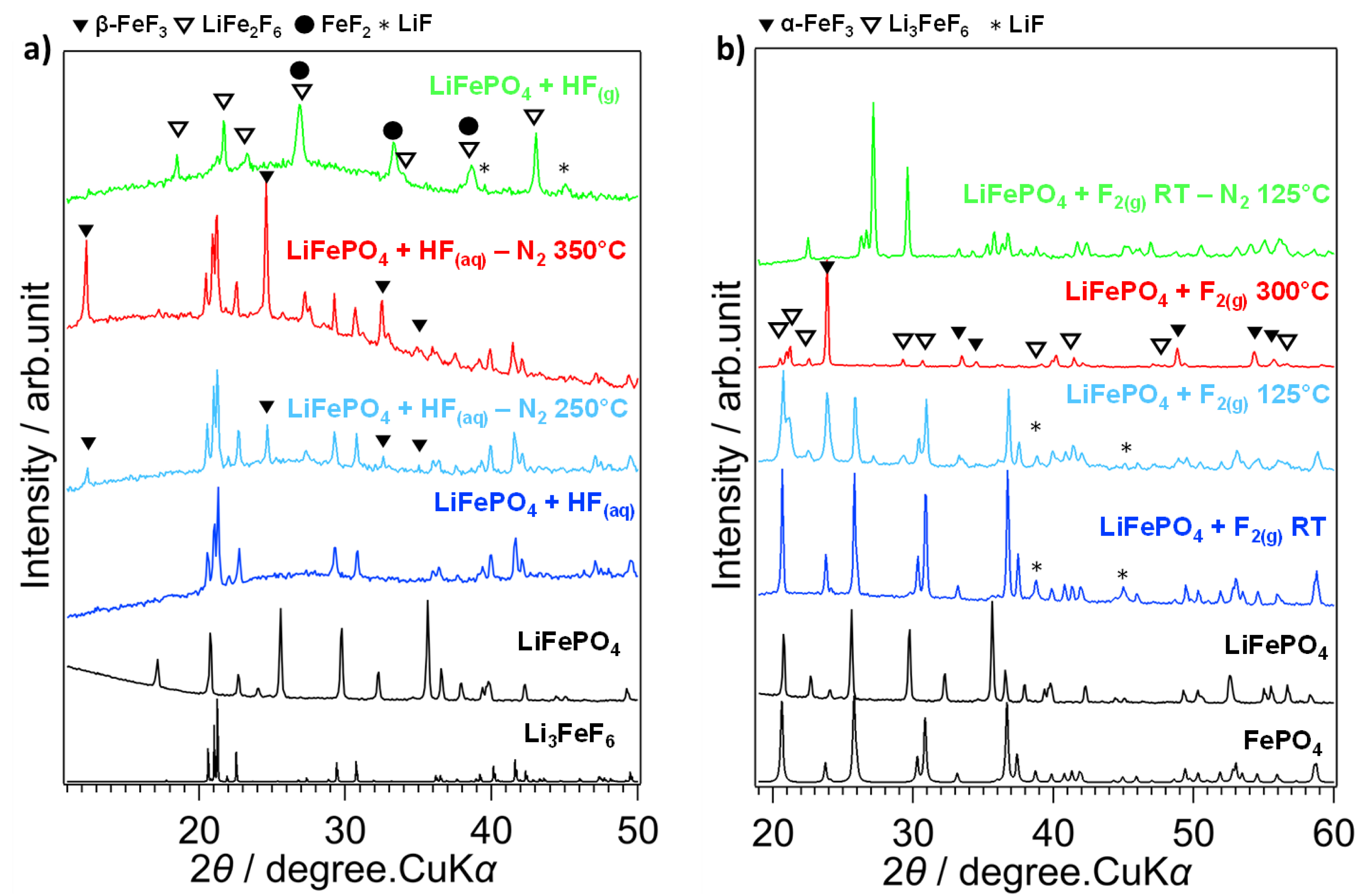
(a) XRD diagrams of fluorinated LiFePO4 by HF(aq) treated by N2 at 250 and 350 °C and fluorinated by HF(g) at RT, (b) LiFePO4 fluorinated by F2(g) at RT, 125 °C and 300 °C, LiFePO4 fluorinated at RT treated at 125 °C under N2.
In the second case, fluorination is carried out in the aqueous phase using HF(aq). LiFePO4 powder is dispersed in a Teflon beaker containing excess HF(aq) and placed on a sand bath at moderate temperature (∼60 °C). The diffractogram of LiFePO4 + HF(aq) is shown in Figure 4a and indicates that a single crystalline phase identified as Li3FeF6 is obtained [31]. When this compound is annealed in an inert atmosphere (N2) at 250 °C and 350 °C (these compounds are designated “LiFePO4 + HF(aq) − N2 250 °C” and “LiFePO4 + HF(aq) − N2 350 °C” respectively), new peaks attributed to HTB–FeF3, for hexagonal tungsten bronze or β-FeF3, are observed, indicating that this phase was already present but below amorphous from RT [32]. Similar to the fluorination by HF(g), the phosphate matrix is degraded at RT. On the other hand, since HF(aq) is an oxidizing medium, all the iron atoms are oxidized to Fe3+. Finally, the mechanism of molecular fluorination, F2(g) fluorination of LiFePO4 seems to take place in two stages: the chemical delithiation followed by the collapse of the phosphate structure (Figure 4b). The complete chemical disinsertion of the Li atoms by fluorine is a favored process even at room temperature (Δr G° = −612.1 kJ/mol), possible because of the robustness of the phosphate network, which does not change during this process, and also because of the total oxidation of Fe2+ to Fe3+. In the second step, at temperatures above 250 °C, the fluorination of FePO4 cores leads to the formation of POF3 and PF5 gases with α-FeF3. Above 250 °C, α-FeF3 reacts with LiF to form Li3FeF6. Above 350 °C, the destruction of the phosphate network is complete, resulting in a mixture of α-FeF3 and Li3FeF6 [33]. It should be noted that in this scenario, the final FeF3 is therefore the excess not reacted with LiF. Only when the phase fluorinated at RT, a mixture of FePO4 and LiF, is brought up to 550 °C in an inert atmosphere as a second treatment, it is possible to obtain the LiFePO4F. It is interesting to notice that this synthesis route produces a mixture at RT equivalent to that obtained for LiFePO4 + HF(aq) − N2 at 350 °C. However, it should be noted that the two synthesis routes differ in the allotropic variety of FeF3 obtained. The or β-FeF3 phase is obtained at low temperature in an aqueous medium, whereas the α-FeF3 form is obtained at high temperature in an anhydrous medium. The structural transition from β- to α-FeF3 is expected at 394 °C [32]. These examples show how, from the same compound treated in different fluorinated media (oxidizing/non-oxidizing, anhydrous/hydrated, etc.) can yield materials of different natures and structures, but all of which are of interest as electrode materials. In an oxidizing medium, the Li3FeF6 phase is obtained at a high or low temperature depending on the nature of the fluorinating agent, whereas the LiFe2F6 phase is obtained when the medium is non-oxidizing. If the oxidizing medium is anhydrous, the α-FeF3 form is obtained, whereas, in a hydrated medium the β-FeF3 form is obtained. As they all offer different lithium diffusion properties, the choice of fluorinating agent is therefore crucial in guiding the synthesis of different materials [34].
It has also been suggested that conversion-type processes may challenge, or even overtake the classical insertion-type mechanism. Transition metal fluorides are conversion materials and have some interesting electrochemical properties such as high theoretical capacity at high voltages, such as FeF3 or CuF2, which provide almost twice the capacity value of classical insertion cathode materials [28]. A patent has been filed by Wang, Feng et al., with a solid solution of mixed metal fluorides formed by mechanochemical reactions. The final mixture allows a high reversibility and a low hysteresis of the battery as compared with single transition metal fluoride [35]. In this sense, starting from a multi-metallic template fluorination, or MMTF, could be a successful strategy to obtain an intimate mixture of mixed metal fluorides [36]. Our interest in using such a structure was initially to mix different metals of interest for the electrochemical application, combined with our expertise in solid gas fluorination. The fluorination of a three-dimensional (3D) MMTF, namely copper-based Prussian blue analog (CuPBA), resulted in a CuF2/FeF3 two-phase mixture with interesting electrochemical properties compared to a similar composition obtained by mechanochemistry. This result was followed by an extension to 2D MMTF, hydrotalcite-type phases, of the general formula
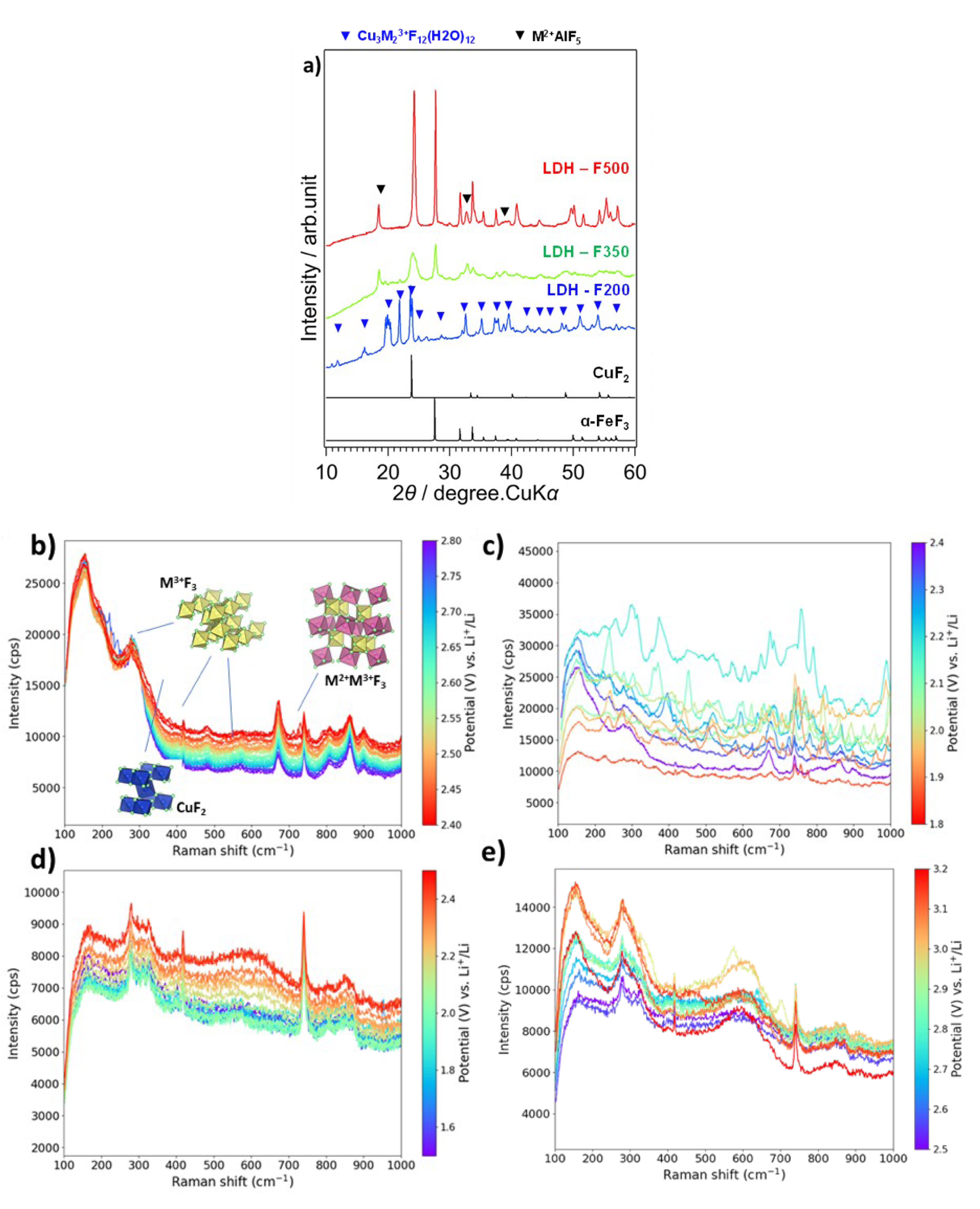
(a) XRD diagrams of fluorinated LDH at 200, 350 and 500 °C, (b) Raman spectra of the F500 electrode in the operando cell with 1M LiTFSI in TEGDME electrolyte during the reduction from 2.8 to 2.4 V and (c) 2.4 to 1.8 V. (d) Raman spectra during the oxidation from 1.5 to 2.5 V and (e) from 2.5 to 3.2 V (purple being the lowest voltage and red the highest). Figure modified from [43].
3.2. Fluorine for the nuclear industry
The world’s fleet of commercial nuclear power reactors requires uranium fuel enriched in the isotope 235U, as only 235U can release energy by fission. In any uranium mineral commonly used for its extraction, U is mainly present in two isotopic forms, namely 0.71% of 235U (fissile) and 99.28% of 238U (fertile). Uranium with a 235U content between 3 and 5% is required for fuel in nuclear power reactors. To achieve isotopic enrichment, all techniques, current or under development, use a gaseous fluorinated uranium compound, namely uranium hexafluoride (UF6). UF6 has two important properties that make it suitable for industrial use: it sublimes at only 56.2 °C despite its high molecular weight and is relatively chemically stable. However, the key to the gaseous enrichment is fluorine, which has a single stable naturally occurring isotope (19F). The industrial gaseous diffusion process has been based on the small mass difference between the two uranium isotopes, due only to the presence of 235U and 238U. However, the diffusion process is now being advantageously replaced by centrifugation, which offers higher efficiency and lower energy consumption. This transition is already underway, as indicated in several recent studies [44, 45, 46].
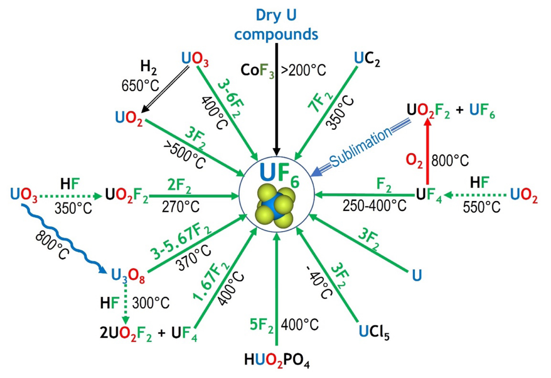
Synthesis routes of UF6 showing the importance of fluorine chemistry (in green) by using F2, CoF3 or HF as fluorinating agent.
UF6 can be synthesized by a variety of routes, shown in Figure 6. The French industrial process starts with several steps to convert U3O8 to UO2, through nitric conversion into UO2(NO3)2, UO3 synthesis and then reduction to UO2. Fluorine is involved in the last two steps, where hydrofluoric acid (HF) converts UO2 to UF4 and then fluorine gas (F2) fluorinates UF4 to UF6. The various fluoride and oxyfluoride compounds involved in the process are studied. These numerous compounds have to be synthesized and isolated in order to understand their crystallographic and chemical properties [47].
From an industrial point of view, whichever chemical pathway is chosen, it is a challenge for companies to comply with international standards of nuclear fuel purity. Contaminants come from uranium ore, chemical products used in the conversion process, and/or fission products from spent uranium. All elements are fluorinated during the synthesis of UF6 and depending on the element, its volatility and solubility in UF6 vary [48]. Magnesium fluoride is a chemical filter to remove of technetium [49], molybdenum [50], or neptunium fluoride [51] from UF6, and has been studied to remove the selected volatile impurity: vanadium oxyfluoride (VOF3) [52]. In order to tailor the physicochemical properties of the chemical filter, in particular the hydroxyl group content and the specific surface area, a fluorination post-treatment was carried out on MgF2.
During transport and industrial processing, UF6 comes into contact with various types of surfaces, either in the gas or in the liquid phase, and undergoes heating and cooling cycles. The corrosion of metals by UF6 is studied to understand the ageing of the metallic surfaces of the fluorination reactors, cooling systems (for the liquefaction of UF6) and storage vessels [53, 54], and a dedicated experimental setup called CORFU (CORrosion in uranium hexaFlUoride) has been designed and built.
4. Conclusion
We have developed several application examples where control of the heterogeneous gas–solid reaction is critical to form the desired phase, to confine fluorination to the extreme surface, to avoid massive decomposition, or to tailor the nature of the C–F bond. With perfect control of inorganic fluorine chemistry, we can address further applications in two major societal areas: materials for energy and the environment, and surface engineering. The range of applications is vast. Examples include the development of composites with natural or carbon fibers made non-polar on their surface by fluorination to lighten structural materials, or new reflectors for very slow neutrons with fluorinated nanodiamonds and graphites.
The group’s historical themes, such as fluorinated (nano)carbons as cathodes for primary lithium batteries, should not be neglected, as they are promising candidates for high added-value applications such as space and medicine. Inorganic fluorine chemistry via gas–solid reactions offers exceptional opportunities for the synthesis of new materials, such as fluorinated diamanes prepared by exfoliation of graphite fluoride with (C2F)n structure type as precursors. The presence of fluorine atoms allows for bandgap engineering of various materials such as graphene, but only if the fluorination is perfectly tailored.
Many challenges remain for gas–solid fluorination, such as incorporating fluorine atoms into highly reactive materials such as boron nitrides or graphitic carbon nitrides. In materials science, a promising approach is to co-dope fluorine with one or two other heteroelements such as oxygen (as seen in fluorinated graphene oxide), sulfur, boron, or phosphorus, to provide additional parameters for application properties. In many cases, gas–solid fluorination can be complemented by plasma fluorination. The complementarity of these processes needs to be developed to meet all the challenges.
Finally, let us explore some of the many avenues. There are numerous examples in the literature of fluorinated photo/electro-catalytic materials for the H2 production, CO2 conversion or pollutants degradation. Some of these materials are the result of modifying a non-fluorinated active matrix by incorporating fluorine atoms. The added value of fluorine in these materials can be diverse: band gap adjustment or better charge separation in photocatalysts, creation of defects or active sites, structural or textural modification of the material, etc. In most cases, these fluorinated materials are obtained by solid-state or hydrothermal synthesis, and in the latter case, generally, only small amounts of fluorine can be incorporated. Few examples of gas–solid fluorination have been reported in the literature. As shown in this paper, the amount of fluorine incorporated, and thus the properties obtained, can be modulated by the choice of fluorination method and fluorinating agent. Uranium hexafluoride is difficult to handle due to its chemical and radiological hazards, but its availability at ICCF, rare in the world, allows it to be used as a fluorinating agent and to study its combination with different materials and gases. In these cases, the objectives of reducing impurities in the UF6 used for enrichment and exploiting large quantities of depleted uranium are perfectly valid.
The reactivity of fluorine with different inorganic matrices shows promising results with the solid/gas reactions of polyanionic and cationic compounds, offering new properties for interesting fluorinated candidates as positive electrodes for secondary batteries. Extensions will be made with tuned cationic compositional templates, but also with other polyanionic compounds, aiming at both a full understanding of the fluorination mechanism and the fluorinated materials with the best electrochemical properties. At a more exploratory level, it has been shown that high-pressure synthesis (>1 GPa) stabilizes structures with different atomic distributions and possible enhanced mobility compared to the equivalent form obtained at ambient pressure, with recent examples being the trigonal forms of LiFe2F6 and Li2MoF6. For the latter, Mo metal and LiF were mixed with CuF2 as a solid fluorine source, the decomposition of which resulted in this fluorinated compound with Mo4+. This fluorination with solid fluorine sources and under drastic conditions opens a different way to discover new properties for classical fluorinated compounds, as well as the stabilization of completely new inorganic materials that cannot be obtained at classical pressures.
Declaration of interests
The authors do not work for, advise, own shares in, or receive funds from any organization that could benefit from this article, and have declared no affiliations other than their research organizations.
Acknowledgements
The authors would like to thank all their academic and industrial partners and the ICCF technical team.