

1 Introduction
Ni metallic catalysts are important for industrial hydrogenation processes (COx, aromatics, etc.) and were discovered to be active for the hydrogenation of organic compounds by Sabatier and Senderens more than one hundred years ago [1–3]. They can be found under two forms: bulk catalysts and supported catalysts. Bulk nickel catalysts include Raney nickel, patented in 1925 [4] and still used in the industry, for example in the synthesis of hexamethylenediamine [5] and in asymmetric hydrogenation in combination with tartric acid [6]. However, one of the major drawbacks of Raney nickel is the lightness of the powder which most of the time implies the use of fluidised bed reactors. To overcome this, nickel particles can be supported on porous oxides. Nickel particles supported on alumina and suitable for catalytic applications are generally obtained as follows: after impregnating alumina with an aqueous solution of hexaaquanickel(II) nitrate and drying the humid solid in air, further thermal treatments in air (~500 °C) and in hydrogen are applied to the catalyst. The major problem encountered during calcination of 5–15 Ni wt% catalysts is the formation of NiAl2O4 and NiO crystallites which are known to be difficult to reduce at low temperature [7–8]. As a consequence, high temperatures (> 600 °C) are required to completely reduce nickel (II), leading to the sintering of the metal to ~20-nm particles.
Facing such problems, a molecular approach of the preparation of supported catalysts has proved to be a suitable way to improve the properties of the catalytic systems [9]. By selecting carefully the metal precursor and the conditions of its treatment once supported, it is possible to tune precisely the nature of the supported active phase: for example, in the preparation of Ni/SiO2 catalysts from nickel-ethylenediamine (en) complexes, which allows one to avoid the formation of nickel silicates and improve the quantity of isolated supported ions [10–11]. In a previous work [12], the use of chelating diamines to prepare highly dispersed Ni particles (1.5 Ni wt%) was found to prevent the migration of nickel ions into alumina during thermal treatments and to contribute to the autoreduction of the nickel complexes when treated in an inert gas atmosphere, without the formation of an intermediate oxidic phase. We decided to investigate the effect of two equivalents of ethylenediamine (1,2-ethanediamine) bonded to nickel on the transformations of the nickel-containing phases during the preparation of a 15 Ni wt% catalyst, closer to those used in catalysis than the 1.5 Ni wt% system. A comparison will be made with a catalyst prepared from [Ni(H2O)6](NO3)2 in the way described above.
2 Results
Two catalysts with 15 Ni wt% were prepared from solutions of two precursor salts: [Ni(H2O)6](NO3)2 (sample A) and [Ni(en)2(H2O)2](NO3)2 (sample B). Details of the preparation steps (deposition, drying in air at 100 °C, thermal treatment up to 500 °C in Ar, followed by treatment in H2 at 500 °C) are given in the ‘Experimental’ section. Throughout the preparation, the speciation of nickel was followed by several techniques. The nature of the first coordination sphere of nickel ions was investigated by UV-Visible-Near Infrared spectroscopy. The existence of crystalline phases was checked by X-Ray Diffraction (XRD) and the changes in the porosity of the system deduced from nitrogen adsorption–desorption isotherms. The reducibility of the nickel species was studied using Temperature Programmed Reduction (TPR). Gases produced during thermal treatments were analysed by Mass Spectrometry (MS). The morphology of nickel-containing phases on the thermally treated catalysts was studied by Transmission Electron Microscopy (TEM) and magnetic measurements.
2.1 Characteristics of the salts and of their solutions
The solid [Ni(H2O)6](NO3)2 and [Ni(en)2(H2O)2](NO3)2 salts exhibited different behaviours upon heating. On a Kofler bench, [Ni(H2O)6](NO3)2 was seen to melt at about 55 °C, whereas [Ni(en)2(H2O)2](NO3)2 decomposed without melting at about 250 °C, which is in line with the literature data [13, 14]. Solubilities were determined experimentally and [Ni(H2O)6](NO3)2 was found to be more soluble than [Ni(en)2(H2O)2](NO3)2 (Table 1). The impregnated solution of the latter exhibited a viscosity 20 times higher than the solution of [Ni(H2O)6](NO3)2 (viscosity of water: 1 cp). It must be noted that crystals of [Ni(en)2(H2O)2](NO3)2 appeared after a few minutes under the shear created by the rotation of the viscometer spindle.
Physicochemical characteristics of the two precursor salts and viscosity of the impregnating solution
| Salt | Temperature (°C) | Solubility (mol l–1 water) | Viscosity (cp) |
| [Ni(H2O)6](NO3)2 | 55 (melting) | 10 | 5 |
| [Ni(en)2(H2O)2](NO3)2 | 250 (decomposition) | 7 | 100 |
2.2 Deposition step
After addition of the solution on alumina and mixing of the powder and the solution, the humid samples A and B were analysed by XRD (20 min of acquisition), between respectively 2θ = 10 and 20°, and 10 and 13°, where intense diffraction peaks characteristic of the salts can be found. On sample A, no other diffraction peaks are observed than those of alumina (Fig. 1a and b). In contrast, a narrow peak was present at 2θ = 11.4° on sample B (Fig. 1c), corresponding to the most intense diffraction line of crystalline [Ni(en)2(H2O)2](NO3)2. A rough evaluation of the crystal size leads to a value of 30 nm, which is much larger than the average pore diameter of alumina (9 nm, in the 4–12-nm range). After leaving sample B in the water-saturated atmosphere of a humidifier during one week, the [Ni(en)2(H2O)2](NO3)2 diffraction peak at 11.4° was not observed any more.
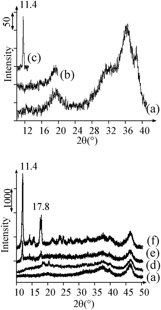
X-ray diffractograms of (a) alumina, (b) humid sample A, (c) humid sample B, and of the dried solids: (d) sample A; (e) sample B after one week in a humidifier; (f) sample B.
2.3 Drying step
After drying at 100 °C, sample A exhibited three UV–Visible–NIR absorption bands in the 300–1300 nm domain (Fig. 2a). A hypsochromic shift of the bands was observed by comparison with those of [Ni(H2O)6]2+ (Fig. 2b). This cannot be explained by the substitution of an aqua ligand by a hydroxyl group of the alumina surface, which is a weaker ligand than H2O and should lead to a bathochromic shift [15]. A substitution of water by some nitrate ions, known to be stronger ligands than H2O on Ni2+ [16], can thus be assumed. Indeed, a few narrow XRD peaks between 2θ = 18 and 21°, corresponding to the most intense diffraction lines of [Ni(H2O)4(NO3)2] (JCPDS 74–666), were noticed on the diffractogram of dried sample A (Fig. 1d). A comparison with the alumina support treated in the same conditions as sample A (impregnation with water and drying) reveals a wide diffraction halo between 12 and 28°. This diffraction halo was interpreted in terms of the presence of small crystallized particles of nickel nitrate in a more or less hydrated form. The broadness of the halo indicates that the limit of detection of crystalline particles has been reached, which means that a population of ~3 nm nickel nitrate crystals has been formed.

UV–visible–NIR spectra of (a) dried sample A, (b) crystals of [Ni(H2O)6](NO3)2, (c) dried sample B, (d) crystals of trans-[Ni(en)2(H2O)2](NO3)2, (e) Ar-treated sample A.
Dried sample B exhibited the UV–Visible–NIR spectrum (Fig. 2c) of trans-[Ni(en)2(H2O)2]2+ (Fig. 2d) [15]. Diffraction peaks of solid trans-[Ni(en)2(H2O)2](NO3)2 were present on the diffractogram (main peaks at 11.4 and 17.8°) (Fig. 1f), more intense and sharper than the peak obtained after deposition. The size of crystals is about 80 nm (instead of 30 nm before drying): the crystals can even less be contained in the alumina mesoporosity. In contrast, the diffractogram of the sample kept for one week in a wet atmosphere resembled to the one of sample A, with the presence of a few sharp peaks from [Ni(en)2(H2O)2](NO3)2 (Fig. 1e).
According to N2-adsorption–desorption experiments on sample A, a slight decrease of the pore volume and average pore size by comparison with the starting support treated in the same conditions showed that small salt crystals agglomerated in the alumina mesopores during drying (Table 2). On catalyst B, the pore volume was dramatically decreased and similar measurements were performed on the sample kept in a humidifier.
Pore volume (Vp, cm3 g–1 alumina) and average pore diameter (Ø, nm) of alumina and samples A and B after drying, Ar-treatment and H2 reduction (sample A)
| After drying | After Ar-treatment | After H2 reduction | ||||
| Vp | Ø | Vp | Ø | Vp | Ø | |
| alumina | 0.55 | 9 | 0.55 | 9 | 0.55 | 9 |
| A | 0.47 | 7 | 0.43 | 7 | 0.48 | 7 |
| B | 0.15 | 7 | 0.32 | 6 | – | – |
Finally, washing dried samples A and B with water removed more than 90% of nickel from alumina. The UV–Visible–NIR spectrum recorded on the filtrate from sample B was the one of cis-[Ni(en)2(H2O)2]2+ (354, 574, 920 nm), the stable form of the complex in solution [15].
Sections 2.4 and 2.5 will describe separately the transformations of samples A and B upon thermal treatments.
2.4 Thermal treatments: sample A
As mentioned in the introduction, the use of ethylenediamine for the synthesis of Ni particles was found to be beneficial after thermal treatments of 1.5 Ni wt% catalysts in an inert gas atmosphere at 500 °C [12]. For the sake of comparison, samples A and B, prepared without or with the use of en, were thermally treated in argon at 500 °C. It is noted that sample A treated in argon has the same characteristics as sample A treated in air.
After thermal treatment in argon of sample A at 500 °C, UV–Visible–NIR and XRD allowed us to identify two phases containing nickel by comparison with the literature data [17–18]: nickel aluminate (bands at 418 and 632 nm (Fig. 2e), no diffraction peak present on the diffractogram) and NiO (band at 715 nm (Fig. 2e), diffraction peaks at 2θ = 37.2, 43.3 and 63° superimposed with those of alumina (Fig. 3a and b)).
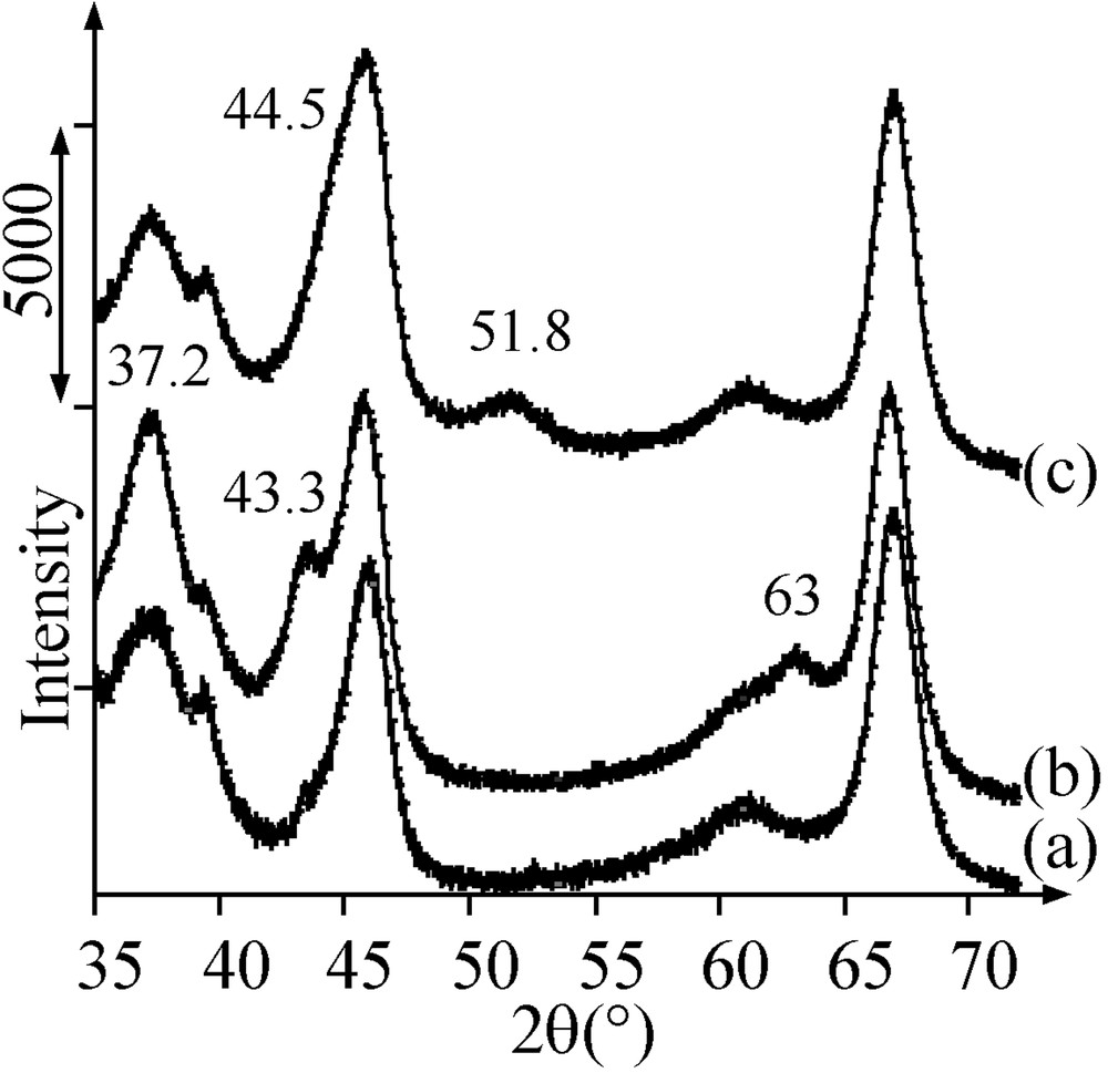
X-ray diffractograms of (a) alumina, (b) Ar-treated sample A, (c) Ar-treated sample B .
The TPR profile of the Ar-treated sample A consisted of two hydrogen consumption peaks: a broad peak at 580 °C and a smaller peak around 750 °C (Fig. 4a). Following the literature [7, 8], the first peak was attributed to the reduction of NiO and the second peak to the reduction of nickel aluminate.
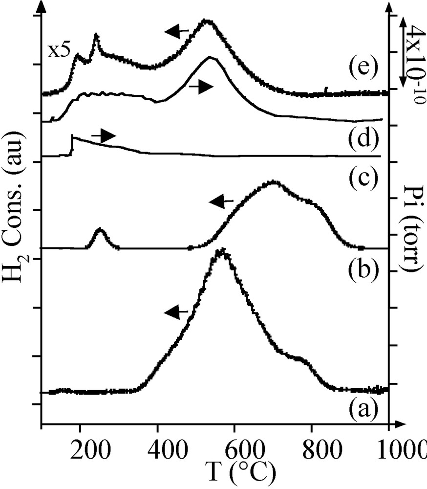
H2 consumption during TPR of (a) Ar-treated sample A, (b) reduced sample A. MS thermograms during TPR of Ar-treated sample B: (c) m/z = 18; (d) m/z = 16. (e) H2 consumption during TPR of Ar-treated sample B.
The pore volume of the Ar-treated sample A was found to be still lower than the one of the support alone (Table 2). This deficit can arise from the presence of nickel oxide or aluminate. Since a 5 Ni wt% sample, which contained nickel only as nickel aluminate (UV–Visible–NIR) in the same quantity as in sample A (TPR), was checked to have the same pore volume as alumina, it is concluded that the decrease in pore volume comes from the presence of nickel oxide. The average size of NiO particles was evaluated by XRD to be about 4 nm.
On sample A, it is necessary to perform a reduction in H2 of the oxidic phases to get metal particles. After thermal treatment in H2, the pore volume and the average pore diameter were still lower than on alumina (Table 2). A few nickel particles were observed by TEM (Fig. 5a, black spots). Their large size distribution (2–9 nm) was centred on 5 nm. A TPR performed on the reduced sample A exhibited three consumptions of hydrogen (Fig. 4b):
- • one small peak at 230 °C, at a lower temperature than that of the reduction of bulk nickel oxide (350 °C); this peak was interpreted as the reduction of superficial nickel oxide on the metal particles;
- • two peaks at 690 and 800 °C, corresponding respectively to the nickel oxide and nickel aluminate species that had not been reduced during the H2 thermal treatment; the consumption of hydrogen for these two peaks corresponded to the reduction of 50% of nickel.
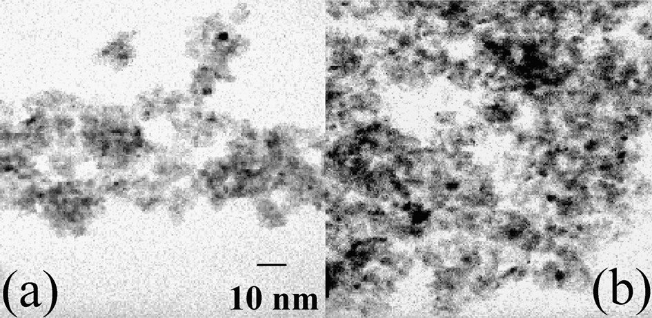
TEM micrographs of (a) reduced sample A, (b) Ar-treated sample B.
Consequently the thermal treatment in H2 at 500 °C led to the reduction of only one half of the nickel (II) introduced on the support.
Magnetic measurements on the reduced sample A confirmed the existence of several nickel-containing phases on alumina. The average magnetic moment per Ni atom at 5 K in a field of 50 kOe was found to be 0.47 μB, significantly lower than for bulk nickel (0.606 μB [19]). This value is consistent with the presence of oxidic phases such as NiO and NiAl2O4 nanocrystallites in the sample [20]. Fig. 6a and b exhibit respectively the zero-field-cooling (ZFC) and field-cooling (FC) magnetization curves for sample A. The ZFC curve evidences a very broad maximum at TB = 100 K and a large irreversibility in the FC process. The broad maximum reflects the presence of a very large size distribution and the irreversibility can be connected to the presence of agglomerates of nickel particles in magnetic interaction [21].
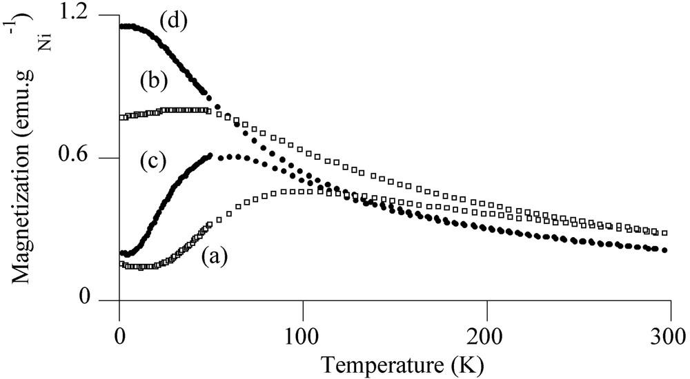
ZFC and FC magnetization curves for reduced sample A ((a) ZFC, (b) FC) and for Ar-treated sample B ((c) ZFC, (d) FC) (applied field = 10 Oe).
2.5 Thermal treatments: sample B
During thermal treatment in Ar of sample B at increasing temperature up to 500 °C, mass spectrometry showed the production of carbon and nitrogen monoxides at 260 °C, corresponding to the oxidation of the ligands by nitrates, and of molecular hydrogen at 350 °C, from the diamine residues remaining after the ligands decomposition (Fig. 7). The pore volume of sample B treated in argon at 500 °C was still much lower that the one of sample A, as well as the average pore diameter (Table 2). X-ray diffractograms showed the disappearance of the crystal salt peaks and the appearance of broad peaks at 2θ = 44.5 and 51.8°, in agreement with the formation of 4-nm Ni0 particles (JCPDS 04-0850) (Fig. 3c). The latter detected by TEM (2–5 nm, average size: 3.5 nm) were more abundant than those obtained on H2-thermally treated sample A (Fig. 5b).
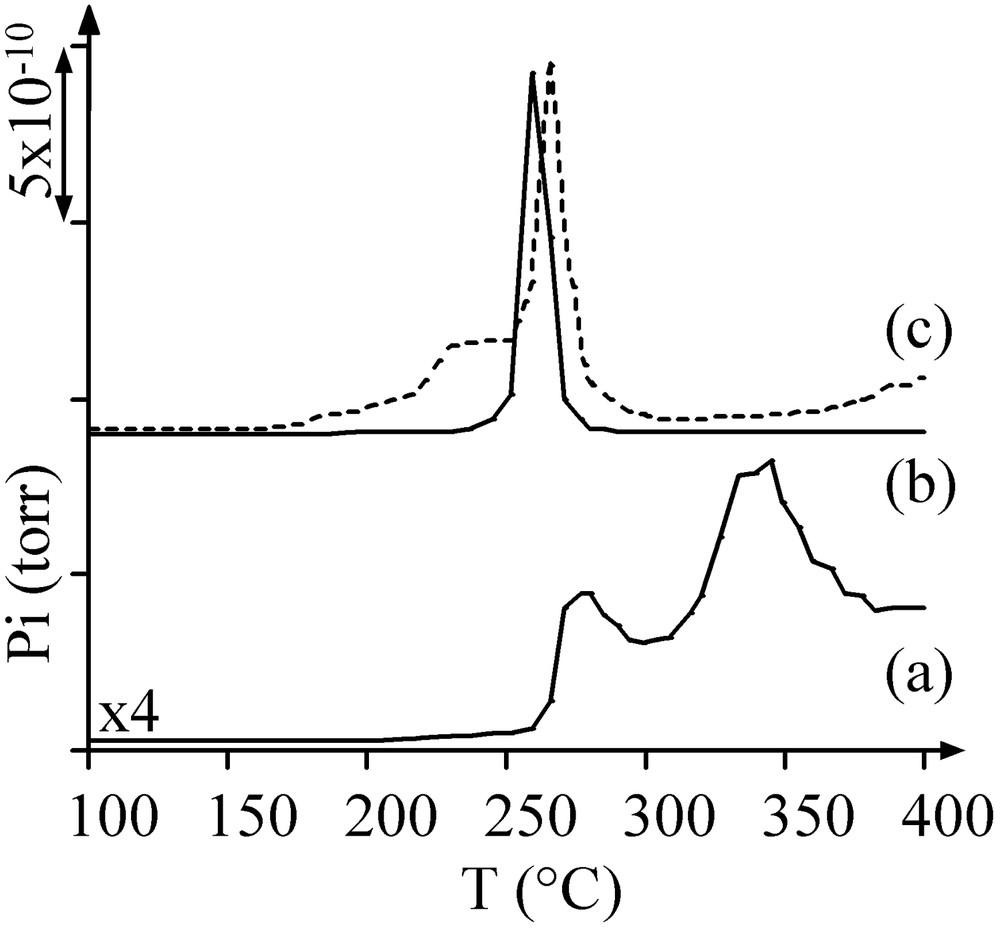
MS thermograms of sample B during Ar treatment: (a) m/z = 2; (b) m/z = 28; (c) m/z = 30 (dotted lines).
On the sample B TPR profile (Fig. 4e), the peak at about 200 °C was attributed to the reduction of superficial nickel oxide (production of water, m/z = 18, Fig. 4c) and, because of MS results (Fig. 4c and d), peaks at 400–650 °C were not attributed to the reduction of oxidic nickel phases like in sample A, but to the methanation of carbon impurities (m/z = 16).
Magnetic measurements were carried out to confirm the reduced nature of nickel on sample B. Fig. 8 shows the hysteresis loop (magnetic moment versus applied magnetic field) at 5 K. The average magnetic moment per Ni atom determined at 5 K in a field of 50 kOe was found to be 0.56 μB. This value is in good agreement with that measured for bulk nickel (0.606 μB), indicating the metallic character of the particles and the absence of bulk oxidic phases. For comparison, Ould Ely et al. have recently reported [22] that non-agglomerated 4-nm Ni0 particles in a polymer matrix saturate in a field of 50 kOe with an average magnetic moment per Ni atom of 0.57 μB. In our case, we notice an absence of saturation that may result from the partial oxidic passivation of surface nickel atoms.
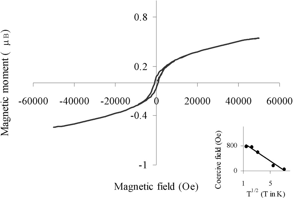
Hysteresis loop for Ar-treated sample B at 5 K (insert: coercive field plotted versus T1/2).
More information could be found from the magnetic properties of the metal particles. Fig. 6 shows the magnetization vs temperature for sample B with an applied field of 10 Oe according to the ZFC/FC processes (Fig. 6c and d). The ZFC curve evidenced a maximum at a blocking temperature TB = 60 K, reflecting the transition between ferromagnetic (T < TB) and superparamagnetic (T > TB) states [23]. Below the blocking temperature, the sample exhibited hysteresis loops. The coercive field could be fitted with the law HC = HC0 (1 – aT1/2) (see insert in Fig. 8) characteristic of well-separated monodisperse magnetic particles [24] (for the principle of the calculation see the ‘Experimental’ section). The fitting led to TB = 1/a2 = 51 K, in relatively good agreement with TB determined by ZFC. From TB we could deduce the anisotropy constant Keff for the nickel particles, Keff = 9.2 × 10⁶ erg cm–3, by taking Vm equal to a sphere of diameter 3.5 nm. This value is more than seven times larger than the bulk nickel value (1.2 × 10⁶ erg cm–3) [25]; an enhanced Keff value has also been reported for superparamagnetic 1.5-nm cobalt particles [26]. Indeed shape and surface anisotropy govern mainly the magnetic anisotropy for small particles and consequently it is not surprising to find a value of Keff much larger than that expected from bulk magnetocrystalline anisotropy.
We have interpreted the consumption of hydrogen observed between 400 and 650 °C on TPR profiles as due to the hydrogenation of carbon traces (0.2 wt% according to elemental analysis). A temperature-programmed oxidation (TPO) in oxygen of Ar-treated sample B monitored by MS showed the production of CO2 at 300 °C. After a treatment of sample B in H2 at 500 °C, no CO2 was any longer produced in TPO. Carbon residues could effectively be removed by hydrogen without any modification of the Ni0 particles size, as checked by TEM.
3 Discussion
3.1 Crystallization upon deposition and drying: role of the salts and of the solutions properties
During the deposition and drying steps, the behaviour of the salts on the surface of alumina leads to systems with dramatically different physicochemical characteristics. The hexaaquanickel(II) nitrate solid is highly soluble. The solution has a viscosity of the same order of magnitude as that of water. Besides, the temperature of drying (100 °C) is higher than the melting point of the crystals of nickel nitrate (55 °C), which can help their dispersion (it can be mentioned that the deposition of molten cobalt nitrate has been used as a method of preparation of dispersed Co catalysts on alumina [27]). All these features suggest the diffusion and crystallization of nickel nitrate inside the pores of alumina, in the form of small dehydrated crystals, the size of which can be evaluated to be 3 nm.
In contrast, crystals form on the support upon deposition from the solution of the less soluble [Ni(en)2(H2O)2](NO3)2; crystallization of poorly soluble salts on the support during impregnation has been described in the literature, for example for alumina-supported molybdenum catalysts [28]. This may be linked with the observation that crystallization occurs during the measurement of viscosity and it cannot be discarded that the high viscosity could be due to the presence of colloids in the solution that deposit on the alumina surface as 30-nm crystals. No redispersion of the crystals is expected to occur during drying since the salt does not melt; by contrast, crystals keep growing during the elimination of water and reach the size of 80 nm. It is possible to decrease the size of these crystals by leaving the sample in a wet atmosphere, thus limiting the evaporation of the solvent. In this case, the disappearance of the 80 nm crystals can be explained by a kinetic phenomenon, i.e., the slow diffusion of the ions in the solution wetting alumina – slow because of the viscosity of the solution. Viscosity appears here to be a factor that hinders the dissolution of salt crystals; in other cases, viscosity can be used as an asset, such as in the preparation of Ni/MCM-41 catalysts with nickel citrate, in which the formation of a viscous film upon drying prevents the crystallization of the complexes [29].
The large 80 nm crystals obtained after drying are obviously located outside the pores of the support. However, no difference is noted between dried sample B and sample B kept in humidifier in terms of porosity – though the latter contains only small crystals like sample A. In the case of [Ni(en)2(H2O)2](NO3)2, we suppose that crystallization occurs over the pore mouth for the larger crystals and at the pore mouth for the smaller crystals. The diffusion of the complexes in a humid atmosphere can lead to a redispersion of nickel, but if the rate of drying is still more important than the rate of diffusion in the pores, the crystals will be forced to form and aggregate at the mouth of the pores by recession of the solvent front [30].
3.2 Absence of a mixed phase between nickel and alumina
It can be noted that in both samples A and B nickel ions are weakly interacting with the support, since a simple washing removes more than 90% of the ions from the surface. The coordination sphere of the complexes studied in the filtrate has not changed compared with the starting salt. We can thus conclude that no mixed phase (e.g., hydrotalcite) between alumina and nickel has been formed during impregnation (hydrotalcite is not decomposed by washing [31]), a feature already observed when nickel complexes containing ethylenediamine are used to prepare catalysts by ion exchange [32–33]. Moreover, no characteristic XRD peaks of hydrotalcites (reported to be at 41 and 45° [32]) have been found.
3.3 Transformations upon thermal treatments: action of the diamine
During thermal treatment in argon of sample A, as well as during thermal treatment in air, two oxidic phases are obtained: nickel aluminate, which does not contribute to significant changes in the support porosity, and NiO which is the cause of the decrease in pore volume compared with alumina. Nickel oxide remains in the porosity where the salt crystals have formed during drying. As evidenced by TPR, only a fraction of NiO can be reduced at 500 °C. Magnetic measurements show that reduced and oxidic phases coexist on alumina, with a size of the Ni0 particles equivalent to the size of the parent NiO particles.
In contrast with sample A, TPR, TEM and magnetic measurements show that a thermal treatment in argon is sufficient to form Ni0 particles by total autoreduction of [Ni(en)2(H2O)2](NO3)2, leading to a system potentially more suitable for hydrogenation catalysis than sample A. The autoreduction of en complexes as a procedure to prepare metallic catalysts has been previously described for gold-palladium catalysts [34]. Carbon impurities can be removed by a subsequent heating in hydrogen, as reported in the literature [35]. On sample B, no oxidic phase able to interact with alumina is ever formed during the succession of thermal treatments in Ar and H2, which explains that the reduction of nickel(II) to Ni0 by the diamine residues is complete. In comparison with a direct reduction of a salt by H2 immediately after drying, the autoreduction method of nickel by the ligand is milder, liberating only a small quantity of hydrogen produced in situ and consumed; the direct reduction of supported nickel nitrate by H2 is reported to be exothermic and difficult to control [36]. Like in the case of sample A, porosity measurements show that a decrease in the support porosity after formation of the metal particles correlates with a decrease in porosity after drying. Ni0 particles appear at the location where the salt crystals had aggregated due to the presence of the diamine in the complex. Since no nickel has migrated into alumina to form nickel aluminate, and thus all nickel is present on the support surface, the decrease in pore volume and pore diameter is stronger than the one on sample A. Another striking difference with sample A is the dramatic decrease in size if we compare the salt crystals of [Ni(en)2(H2O)2](NO3)2 (several tens nanometres) and the metal particles, which are monodisperse (2–5 nm, TEM/magnetic measurements). The low dispersion of nickel after drying is thus not ominous for the synthesis of a dispersed catalyst. A possible explanation of this phenomenon may lie in the splitting of the crystals during the exothermic combustion of the ligands by nitrates during the thermal treatment, prior to reduction [14].
4 Conclusions
The use of a chelating diamine in the preparation of 15 Ni wt% supported catalysts has been found to be effective to obtain nickel metal particles by a one-step thermal treatment at 500 °C in argon, leading to a complete autoreduction of the complexes. Small monodisperse nickel particles (2–5 nm) are formed after destruction of the larger [Ni(en)2(H2O)2](NO3)2 crystals that had formed during impregnation. The successive states of the catalysts strongly depend on the presence of the ligand and concern the solution (its viscosity and the solubility of the salt) or the solid form of the complex (melting point or decomposition reactions of the salt crystals). Thanks to these decomposition reactions, the formation of the salt crystals during impregnation is not necessarily detrimental to the synthesis of dispersed Ni0 particles.
5 Experimental
The salt [Ni(en)2(H2O)2](NO3)2 was prepared following a procedure described in the literature [37]. Ethylenediamine (Fluka) was introduced in a solution of commercial Ni(NO3)2.6 H2O (Aldrich) in the stoichiometry en/Ni = 2. The salt was crystallized by evaporation of water in vacuum at 70 °C and then dried in a dessicator. The melting and decomposition points of Ni(NO3)2.6H2O and [Ni(en)2(H2O)2](NO3)2 were measured on a Kofler bench. The viscosity of the solutions was measured on a Brookfield DVII+ viscometer (shear rate = 100 rpm). A spindle immersed in the fluid was driven through a calibrated spring. The viscous drag of the fluid against the spindle was measured by the spring deflection.
γ-Alumina (EC 1285) was provided by the ‘Institut français du pétrole’ (IFP) and used after grinding and milling: Ø = 150–250 μm, specific surface area = 200 m2 g–1, void volume (determined by water impregnation) = 0.68 cm3 g–1.
Catalysts were prepared by the incipient wetness impregnation method. The void volume of alumina was filled with a solution of the precursor salt (3.8 mol l–1 water). After addition of the solution on alumina under mechanical homogenisation, the humid solid was dried in air at 100 °C for 30 min. It was then thermally treated in argon (flow = 100 ml min–1) up to 500 °C (heating rate = 7.5 °C min–1) and kept 1 h at 500 °C. A subsequent treatment in pure H2 (flow = 100 ml min–1) was performed with a heating rate of 7.5 °C min–1 followed by 1 h at 500 °C.
Elemental analyses of nickel were performed by ICP (CNRS Service of Analysis, Vernaison) and in carbon by catharometry after fast calcination of the sample in air (Central Service of Analysis, University Pierre et Marie Curie).
Powder X-ray diffraction (XRD) measurements were performed on a Siemens D500 diffractometer, using the Kα radiation of copper (1.5418 Å). X-ray diffraction was used as a method to assess the order of magnitude of the crystal sizes (above 3 nm), after drying and heating treatment, applying whenever possible the Laue-Scherrer equation to two peaks of the crystals, each corresponding to a single diffraction.
UV–Visible–NIR absorption spectra were obtained on a Varian Cary 5E spectrophotometer in the transmission mode (solutions) using water as a reference and in the diffuse reflectance mode (solids) using Teflon as a reference. The resolution was 0.2 nm. After collection, the spectra were treated using the Kubelka-Munk transform.
Nitrogen adsorption–desorption isotherms were performed at –196 °C on a Micromeritics ASAP 2010 apparatus, after evacuation at 150 °C. The BET model and BJH analysis (on the desorption branch) were used to estimate respectively the specific surface area and the pore volume of the samples. No contribution from a micropore volume was found.
The production of gases during thermal treatments (performed in argon, hydrogen or oxygen) was studied using a HPR20/DSMS mass spectrometer (MS) connected to the outlet of the reactor via a heated capillary. The pressure in the ionisation chamber was 2 × 10⁻⁶ torr.
Temperature programmed reduction (TPR) was carried out on 100 mg of the samples, in a H2 (5 vol%)/Ar mixture (25 ml min–1), using catharometry to detect the consumptions of hydrogen. The heating rate was 7.5 °C min–1. Quantification of hydrogen consumption was realized by integration of the peaks after calibration using the reductive gas mixture and pure argon. Nickel oxide NiO (Prolabo) was used as a reference.
Transmission electron microscopy (TEM) experiments were performed on a JEOL 100 CXII UHR microscope. Measurements of the reduced nickel particle sizes on several micrographs led to the statistical distribution of the particle sizes. The average particle size was calculated as the first-order moment of the statistical distribution.
The magnetization measurements were carried out using a MPMS 5.5 Quantum Design equipped with a SQUID detector. The temperature was varied from 2 to 300 K and magnetic fields up to 50 kOe were applied. In the case of well-separated monodisperse magnetic particles [24], the law HC = HC0(1 – a T1/2) can be used with H0C being the coercive field at absolute zero and a2 = (kB/K V) ln(τm f0), where kB is the Boltzmann constant (1.38 × 10⁻¹⁶ erg K–1), K the anisotropy constant, V the volume of the particles, τm the characteristic time of the magnetometer and f0 a frequency typically of 109 Hz. The blocking temperature can be calculated as TB = 1/a2. TB is linked with the anisotropy constant Keff, according to the law Keff Vm = 25 kB TB, where Vm is the mean volume of the particles [23]. Conversions to the SI units can be made as follows: 1 Oe = 103/4 π A m–1; 1 erg = 10–7 J.
Acknowledgements
The authors would like to thank Thierry Faure (‘Laboratoire TP Fluides et Thermique’, ‘Université Paris-Sud’, Orsay, France) for his help in the measurements of viscosities, Pr. François Bozon-Verduraz (‘Laboratoire de chimie de la matière divisée et catalyse’, ‘Université Denis-Diderot’, Paris, France) for providing access to the UV–visible–NIR spectrometer, and Michel Lavergne (‘Laboratoire de réactivité de surface’, ‘Université Pierre-et-Marie-Curie’, Paris, France) for the TEM measurements.