

1 Introduction
In natural photosynthesis, light is absorbed by photonic antenna systems consisting of a few hundred chlorophyll molecules. These devices allow fast energy transfer from an electronically excited molecule to an unexcited neighbor molecule in such a way that the excitation energy reaches the reaction center with high probability. Trapping occurs there. The anisotropic arrangement of the chlorophyll molecules is important for efficient energy migration. In natural antennae the formation of aggregates is prevented by fencing the chlorophyll molecules in polypeptide cages. A similar approach is possible by enclosing chromophores inside a microporous material and by choosing conditions such that the cavities are able to uptake only monomers but not aggregates. Zeolites are suitable hosts for specific organization of chromophores and for the investigation of changes of their optical properties due to interaction with different environments [1,2]. In most of our experiments we have been using zeolite L as a host because it was found to be very versatile. Its crystals consist of an extended one-dimensional tube system and can be prepared in a large size range. We have filled the individual tubes with chains of different dye molecules and we have shown that photonic antenna materials can be prepared, not only for light harvesting within the volume, but also for radiationless transport of electronic excitation energy to a target molecule fixed at the ends of the nanochannels as well as with an injector molecule fixed at their ‘entrances’. The dye molecules in Fig. 1 are represented by rectangles. The molecule, which has been excited by absorbing an incident photon, transfers its electronic excitation to another one. After a series of such steps the electronic excitation reaches a luminescent trap, pictured as dark rectangles. The energy migration is in competition with spontaneous emission, radiationless decay, quenching, and photochemically induced degradation. Fast energy migration is therefore crucial if a trap should be reached before other processes can take place [3].
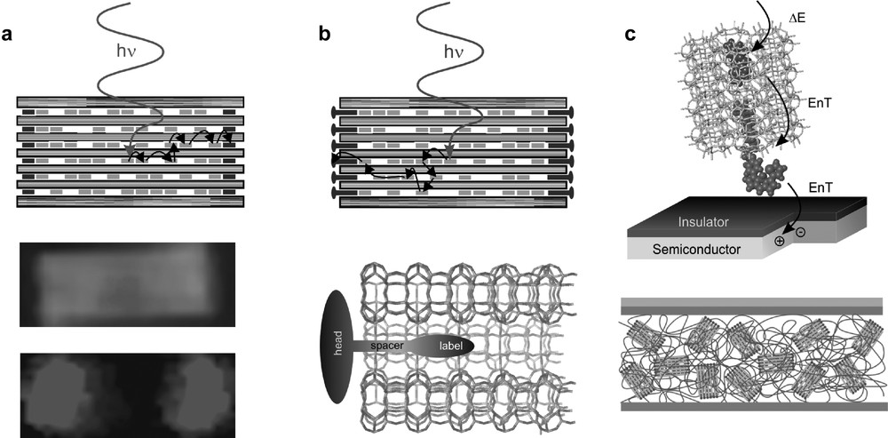
Three stages of organization from left to right. (a) Dye-loaded zeolite L crystal; electronically excited donors (light gray rectangles) inside the zeolite L transfer their energy to acceptors (dark gray rectangles) at the left and right of the crystal. A 800-nm-long crystal containing a donor in the middle part and an acceptor at both ends as seen in an optical microscope is shown (middle: donor luminescence; lower: acceptor luminescence). (b) Antenna system with stopcock molecules as external traps and picture of a stopcock at the end of a channel. The stopcock generally consists of a head, a spacer, and a label. (c) Top: Energy Transfer (EnT) from a photonic antenna to a semiconductor, creating an electron-hole pair in the semiconductor (radiationless near field process). Bottom: EnT from acceptors inside the channels via a stopcock to a polymer which is drawn as a ribbon. Masquer
Three stages of organization from left to right. (a) Dye-loaded zeolite L crystal; electronically excited donors (light gray rectangles) inside the zeolite L transfer their energy to acceptors (dark gray rectangles) at the left and right of the crystal. A ... Lire la suite
We consider the supramolecular organization of the dyes inside the channels as a first stage of organization. It allows light harvesting within a certain volume of a dye-loaded zeolite and radiationless energy transport to the ends of the cylinder or from the ends to the center. A second stage of organization is the coupling to an acceptor or donor stopcock fluorophore. A third stage of organization is the coupling to an external device via a stopcock intermediate. We distinguish between the coupling to artificial reaction centers of molecular, macromolecular, and macroscopic dimension. The wide-ranging tunability of these highly organized materials offers fascinating new possibilities for exploring excitation energy transfer phenomena and challenges for developing new photonic devices [4].
2 Host materials
Because of their well-defined internal structure with uniform cages, cavities or channels, zeolites are extremely well suited as host materials. Classical zeolites are inorganic nanoporous crystalline aluminosilicates. They can be thought of as sponge-like material with channels and cages that extend regularly across their entire structure. We show the framework of zeolite A (LTA) and zeolite L (LTL) in Fig. 2. It illustrates that although the various zeolites are chemically very similar, they have different geometrical properties. Zeolites have higher mechanical and thermal stability compared to organic hosts. There are approximately 40 naturally occurring and well over 100 synthetic forms of zeolites [5].

Two zeolite frameworks: (a) LTA, having cages and (b) LTL, having a one-dimensional channel system [5].
Control of the shape and size of the crystals is a prerequisite for particular applications. Large crystals of a few hundred to a few thousand nm are very useful for studying the optical and photophysical properties of dye-zeolite composites on single crystals by means of optical microscopy methods. Crystals in the range of a few tenths to a few hundred nm are needed for high efficiency photonic antenna materials, useful as fluorescent microprobes in cell biology and analytical chemistry, for developing a new generation of dye-sensitized solid state solar cells, or for preparing a new generation of light emitting diodes. Fine-tuning of the size of zeolite L crystals in the range of 30 nm up to 7000 nm can be realized by changing the composition of the starting gel for otherwise similar reaction conditions [6,7]. This means that materials covering a volume range of seven orders of magnitude are available. We illustrate the morphology and channel structure of zeolite L crystals in Fig. 3. Zeolite A, which has a cubic framework, forms cubic crystals; for details we refer to [8].

Morphology and channel structure of zeolite L crystals. Left: Side and top view of a zeolite L crystal. The length of the upper crystal is about 900 nm; the diameter of the lower crystal is about 850 nm. Middle: A schematic view of some channels running through the whole crystal. A zeolite L crystal of 600 nm diameter consists of about 96,000 strictly parallel channels. Right: Enlargement which shows details of a channel with a dye and its electronic transition moment (indicated as double arrow) which is parallel to the c-axis for long molecules and tilted for shorter ones. The diameter of the channel window is 0.71 nm and the largest free diameter is 1.26 nm. The length of a unit cell is 0.75 nm and the center to center distance between two channels is 1.84 nm. Masquer
Morphology and channel structure of zeolite L crystals. Left: Side and top view of a zeolite L crystal. The length of the upper crystal is about 900 nm; the diameter of the lower crystal is about 850 nm. Middle: A ... Lire la suite
3 Guest molecules
A representative selection of dye molecules which have been inserted into zeolite L is shown in Fig. 4 where we also give abbreviations used in this article. It is important to distinguish between three types of dye molecules. (i) Molecules small enough to fit into a single unit cell. Some examples are biphenyl (BP), methyl viologen (MV2+), fluorenone, naphthalene, and anthracene. (ii) Molecules the size of which makes it hard to guess if they align along the c-axis or if they find a way to fit into a single unit cell. Ox+, Py+, and Th+ are molecules of this type. (iii) Molecules which are so large that they have no other choice but to align along the c-axis. Many examples belong to this category. POPOP, DMPOPOP, MBOXE, pTP, DPH are some of them [4]. A different kind of material is obtained by means of a ‘ship-in-a-bottle’ synthesis [9,10]. A prominent example is [Ru(bpy)3]2+ the synthesis of which in zeolite Y has been studied in detail [11]. A more recent example for which we will give more details below is quantum-sized silver sulfide which was prepared in zeolite A [8,12].
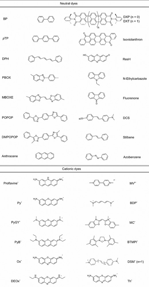
Selection of dyes (and abbreviations) which have been inserted in zeolite L.
The fact that appropriately chosen dyes cannot glide past each other because the channels are too narrow is the underlying principle for preparing photonic antenna materials as explained in Fig. 1. This was for the first time reported in 1998 for Py+ and Ox+ [13] and later much further developed [14]. A review about the standard method for preparing a large variety of sandwich materials with fascinating properties has recently been published [4a]. The first step results in a material we name dye1-zeolite L. Next dye2 is inserted. Conditions must be chosen such that dye1 has no chance to exit the channels at the beginning of this second step. Once a dye2 molcule has entered each channel on both sides, the dye1 molecules have no chance to escape anymore. On the contrary, they are pushed deeper into the channels by the following dye2 species, and we obtain the dye2, dye1-zeolite L material. The same procedure is repeated for dye3. The resulting material is the dye3, dye2, dye1-zeolite L material [4a]. Different insertion methods can be combined. Dye1 can be a cationic dye. Hence it is inserted by cation exchange. Dye2 can be a neutral dye; hence we insert it from the gas phase and so on. Structures with more than three different dyes can be prepared if desired. The stacking of the dyes is often easily visible in an optical fluorescence microscope equipped with polarizer and appropriate optical filters for sufficiently large crystals, or even better by means of confocal microscopy.
4 The stopcock principle
Extension beyond the interior of the zeolite crystals is achieved by selectively positioning molecules at the entrances of the zeolite channels. The properties of these so-called stopcock molecules are designed to allow communication between the guest molecules on the inside with materials or molecules on the outside. These can be an artificial reaction center of (i) molecular dimension (e.g., a head of a stopcock molecule which changes its properties as a function of pH, or of the presence of a specific molecule), (ii) macromolecular dimension (photoconducting or conducting polymer, quantum dots, semiconductor) [15], and (iii) macroscopic dimension (semiconductor, conductor, quantum wells) [16]. Furthermore, the stopcock molecules can prevent small molecules like H2O or O2 from diffusing into the interior of the crystals. Typical stopcock molecules are composed of three parts: a narrow label which can penetrate into the channels of the zeolite, a head too large to enter the channels, and a flexible spacer connecting head and label, as illustrated in Fig. 5 [17].

Stopcock principle. Left: The typical shape of a stopcock molecule consisting of a head which is to large to enter the channel and a tail, typically composed of a spacer and a label penetrating into the channel. Right: A few channels closed on both sides by means of stopcock molecules.
We distinguish between reversible stopcocks [18] attached to the channel by adsorption of the tail inside of them, electrostatically bound stopcocks to the negatively charged channel of zeolite L, and irreversibly bound stopcocks anchored by covalent bonds. An example for each type is shown in Fig. 6. In order to adsorb a reversible stopcock molecule, its interaction with the zeolite channel needs to be stronger than its interaction with the solvent. Labels with polar moieties, especially carbonyl groups, have proven to be advantageous due to their specific interaction with sites inside the channels [19]. It seems that electrostatically bound stopcocks are especially easy to handle [20]. An irreversible stopcock has to provide a moiety able to undergo a reaction with surface hydroxyl groups of the zeolite to yield at least one covalent bond. Alkoxysilane groups are widely used for the modification of silica surfaces. 3-aminopropyltriethoxysilane for example is a common reactant for this purpose. Reaction in dry solvent, usually toluene, leads in this case to nucleophilic displacement of the silane ethoxyl by surface hydroxyl, resulting in the liberation of ethanol and the formation of Si–O–Si linkages [15,16]. An irreversible stopcock molecule as shown in the lower right part of Fig. 6 is first adsorbed by incorporation of the label and subsequently covalently anchored by reaction of the ethoxysilane groups with surface hydroxyl groups located at the channel entrances [21].
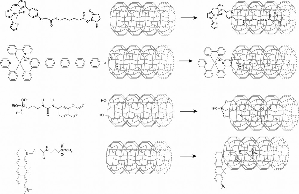
Different ways to fix a stopcock. From top to bottom: reversible stopcock attached to the channel by adsorption of the tail inside of them, electrostatically bound stopcock, and two examples of irreversibly bound stopcocks anchored by covalent bonds.
For communication via energy transfer, the stopcock molecules need to contain a sufficiently strong fluorescent unit. Depending on the application, the fluorophore can be located on the head or on the label moiety. In the latter case the fluorophore is protected by the zeolite framework. Fluorescent head moieties on the other hand have the property of being closer to the external surface, which is desirable for communication with the environment. Efficient trapping or injection of excitation energy furthermore requires a sufficiently large spectral overlap between the stopcock molecules and the donor or acceptor molecules inside the zeolite channels.
We show in Fig. 1c as an example the coupling to a semiconductor device for energy transfer from the photonic antenna through an insulating layer creating an electron-hole pair in the semiconductor. The coupling of zeolite antennae (see Fig. 1c) to a luminescent or photoconductive polymer offers possibilities for the development of novel LED materials. When embedding zeolite crystals in polymer films, methods to covalently anchor dye molecules on the outer surface of the zeolite can be employed to enhance the contact area between polymer and zeolite. Such grafting procedures, which use silane reagents to couple the dyes to the surface of the crystals, have been applied to immobilize dye molecules in mesoporous silica [22]. We have recently prepared a polymer embedded, surface modified Ox+-zeolite L, for which we observed transfer of electronic excitation energy from the photoconductive polymer to the dye molecules at the external zeolite surface and ultimately to the Ox+ molecules located in the channels [15].
5 Zeolite monolayers
The preparation of monolayers of zeolite crystals has first been reported in 1995 [23], and later optimized by several other groups [24]. Recently the first example on specific chemical reactions such as in situ or ‘ship in a bottle’ synthesis on high-quality zeolite monolayers has been demonstrated [25]. The procedure is explained in Fig. 7. First, zeolite A crystals are deposited as monolayers on quartz by sedimentation at room temperature, step 1. In the next step, 2, the physisorbed crystals are fixed by heating the layer up to 600 °C. The layers are now stable in aqueous environment, so that in step 3 the insertion of Ag+ into zeolite A by means of ion exchange can be carried out in a well controlled way. Then the layers are dried in high vacuum to remove water from the zeolite cages. The samples are now ready for exposure to H2S(g) which diffuses into the zeolite cages and reacts with Ag+ yielding AgSH and a proton, step 4. The samples are then rehydrated in step 5 so that AgSH becomes sufficiently mobile and the desired (Ag2S)n clusters are formed and stabilized in the α-cages of zeolite A. An easy parameter to vary is the amount of exchanged Ag+, by which the size of the clusters can be controlled, so that for example either green luminescent zeolites containing Ag2S monomers or orange luminescent zeolites containing Ag4S2 are obtained [12].

Formation of stable zeolite A monolayers on quartz and subsequent ‘ship-in-a-bottle’ synthesis of luminescent silver sulfide clusters, step 1–5. (A) Electron micrograph of a single zeolite A crystal with an edge length of 3000 nm. (B) Optical microscopic picture of a monolayer of zeolite A crystals of the same size, seen in transmission. (C) Electron microscopic picture of a zeolite A monolayer.
An important step towards adding further functionality to dye-zeolite L systems and achieving a higher level of organization is the controlled assembly of the zeolite crystals into oriented structures. In the case of zeolite L this implies the alignment of the unidirectional channels over a large number of crystals. Yoon and coworkers have shown that crystals of zeolite A and ZSM-5 can be covalently attached to a substrate by the use of linker molecules, thereby yielding robust monolayers [24b]. We have applied these methods to zeolite L with the goal to arrange the cylindrical crystals such that most of them are standing on their base. In such an arrangement the dye-filled channels of the zeolites would run perpendicular to the substrate surface, allowing efficient transport of electronic excitation energy towards the zeolite-substrate interface. Using crystals with an aspect ratio (length to diameter) of 1.4 resulted in monolayers with 45% of the crystals in the desired orientation (see Fig. 8, left). We have recently been able to prepare hockey-puck shaped crystals which yield monolayers with 95% standing crystals (see Fig. 8, right). Further optimization of the morphology (flat basal planes) and size distribution is expected to lead to monolayers with higher packing density.
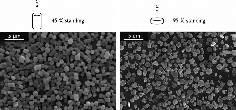
Monolayers of zeolite L on glass stabilized by covalent linkers. The crystal morphology determines the degree of orientation.
6 Photophysical properties
Electronic excitation energy transfer in organized dye-zeolite L systems leads to fascinating material properties which have been reported in a number of publications [4] and we therefore focus on some other properties. The refractive index of zeolites is in the same range as that of quartz. It is expected to vary to some extent depending on the cations, the water content, and the dye loading. Thus optical effects observed in tiny glass fibers due to total internal reflection are expected to appear in zeolite crystals as well. Taking into account these effects, a zeolite crystal can also be considered as a microresonator [4c]. We wonder to what extent such a tiny resonator can be described by classical optics, since its dimensions are in the order of the wavelength of the light. We now report some recent observations we made by exciting two different materials with a pulsed laser. In one of these experiments a layer of Ox+-zeolite L crystals was excited with 5-ns laser pulses at 532 nm. The excitation power was increased from 0.2 to 5.5 MW/cm2. Up to an excitation power of 2 MW/cm2, the measured emission spectra matched the fluorescence spectra. A new peak at 625 nm started to develop at an excitation power of 2 MW/cm2. Taking the ratio of the intensity of the new peak at 625 nm and the fluorescence peak at 660 nm, a threshold at about 2 MW/cm2 is observed (inset of Fig. 9). The peak at 625 nm is considered as laser action of the dye-loaded zeolite L material, since threshold behavior is common for lasing. Full proof has been established that Ox+-zeolite L crystals are actually lasing [4e].
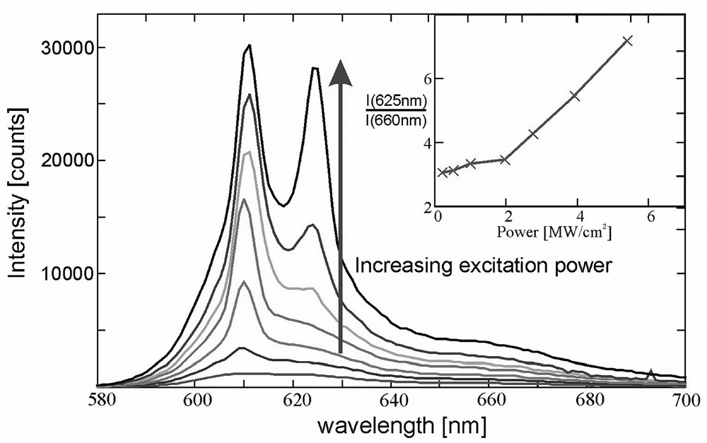
Fluorescence spectra of a layer of Ox+-zeolite L crystals at increasing excitation power. The inset shows the ratio between the peaks at 625 and 660 nm. The size of the crystals was 800 nm on the average and the loading was 0.05 Ox+ per unit cell.
Similar experiments were made with zeolite A crystals containing silver sulfide clusters. Such crystals containing K+ as co-cations show at room temperature a deep red photoluminescence with maximum emission at 735 nm. The light emission is enhanced at the corners of the cubic crystals, as illustrated in Fig. 10a. A layer of Ag2S-zeolite A crystals was excited with 5 ns laser pulses at 450 nm. The excitation power was increased in several steps, as shown in the inset of Fig. 10b). Up to an excitation power of 90 MW/cm2, the measured emission spectra matched the fluorescence spectra. Above this intensity, two new peaks started to develop, one at 590 nm stemming from a band which is otherwise only observed at low temperature (for details see [25]) and a more intense one at 767 nm. Taking the ratio of the intensity of the new peak at 767 nm and the fluorescence band at 735 nm reveals a threshold at about 90 MW/cm2.

(a) Luminescence spectrum of K+-zeolite A containing silver sulfide. Excitation was performed at 450 nm at room temperature. Inset: confocal microscope image showing a single luminescent zeolite A crystal of an edge length of 3000 nm. (b) Luminescence spectra of a layer of K+-Ag2S-zeolite A crystals at increasing excitation power. The sample was excited at 450 nm with a pulsed laser. The inset shows the ratio between the intensity at 767 and 735 nm.
The question arises if materials with high up-conversion efficiency could be made. To our knowledge, such dye-zeolite materials have not yet been reported. It seems, however, to be rather probable that due to the possibility to pack two kind of dyes with appropriate spectral characteristics very closely, without changing the electronic properties of the dyes which still act as monomers, either in form of layers or as random mixtures, up-conversion materials with high efficiency can be made for which the following mechanism holds:
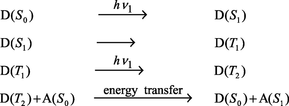
It seems to be feasible to design down-conversion materials in a similar way for the same reasons. Clever up- and down-conversion schemes have been discussed in connection with third generation solar cells. Theory predicts the possibility of considerably improving single band gap photocells [26].
7 Solar cells sensitized by dye-zeolite antenna materials
In view of practical applications the coupling of dye–zeolite composites to external devices is of special interest. A challenging application is the development of new photonic devices for solar energy conversion. A few examples are given in Table 1.
Overview of new photonic devices for solar energy conversion, incorporating antenna-sensitized materials. The sensitization occurs via electronic excitation energy transfer. For each device, the role of the sensitizing antenna is indicated
| Redox-systems based solar cells | ||
| Thin film solar cells | Plastic solar cells | Dye-sensitized solar cells |
|
| Oriented layers of monodirectional 300–600 nm crystals |
The zeolite systems described so far constitute bidirectional antennae. Due to the symmetric arrangement of different dye molecules excitation energy is transported along the one-dimensional channels in both directions. For coupling to a macroscopic device such as a semiconductor, excitation energy transport in only one direction might often be preferable. The synthesis of monodirectional (asymmetric) antennae, where this transport occurs in one direction only, is currently under investigation in our laboratory. Fig. 11 illustrates two pathways which can be tried. We can for example first modify the substrate by preparing a monolayer of stopcocks and then add a zeolite in such a way, that the tail of the stopcocks penetrates into the channels. The fixed zeolite crystals can then be filled from the top with any desired chromophores. Another possibility is to stack crystals with differently charged stopcocks on top of each other, as illustrated on the right side of Fig. 11.

Two strategies for the preparation of stopcock modified monodirectional materials.
A dye-zeolite composite prepared as a monodirectional antenna would open possibilities for different types of sensitized solar cell. Arranging small composite crystals with their c-axis perpendicular to the surface of a semiconductor would allow transport of the excitation energy towards the zeolite-semiconductor interface by energy migration. Stopcock molecules are placed at the channel ends to allow energy transfer. Only a very thin semiconductor is needed in this case, because the electron-hole pairs form near the surface. The transfer of electrons from antenna to semiconductor can be prevented by introducing an insulating layer. Energy transfer from dye-zeolite crystals to bulk silicon has recently been demonstrated [16]. Energy can also be transferred from the semiconductor to the antenna composites by reversing the current and putting a voltage over the semiconductor. The dye-zeolite composites on the semiconductor surface subsequently lose their energy by emitting light. The color of the emission can be tuned by adapting the ratio of blue, yellow, and red fluorescent dyes. Higher luminescence efficiency is expected for such a system compared to conventional LEDs. The principle of these monodirectional antenna systems is illustrated in Fig. 12. Options for combining the antenna systems with redox-based dye-sensitized photovoltaic cells exist (see Table 1), but will not be further discussed here.
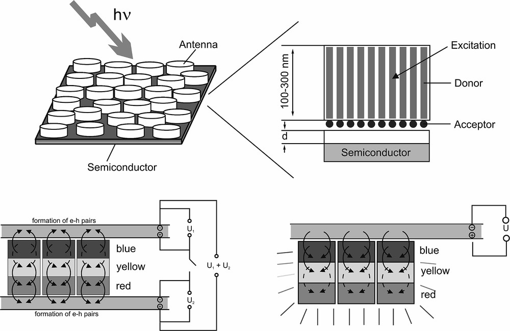
Top: Sensitized solar cell based on dye-loaded zeolite L antenna systems. The antenna systems absorb light and transport their energy mainly along the c-axis of the crystals to the semiconductor surface. Electron-hole pairs are formed in the semiconductor by energy transfer from the antenna system to the conduction band of the semiconductor. Bottom left: Tandem solar cell where monodirectional antenna systems with blue, yellow, and red dyes are put between two n-type semiconductors with different band gaps. Bottom right: Light-emitting nanocrystals. The electrical source supplies excitation energy that can be transferred from the semiconductor to the nanocrystals. The dyes inside the crystals lose their energy by fluorescence because of their high fluorescence quantum yield. Masquer
Top: Sensitized solar cell based on dye-loaded zeolite L antenna systems. The antenna systems absorb light and transport their energy mainly along the c-axis of the crystals to the semiconductor surface. Electron-hole pairs are formed in the semiconductor ... Lire la suite
8 Summary
The concept of filling luminescent dyes into hexagonal zeolite crystals consisting of one-dimensional channels with molecular diameter and tunable length leads to new inorganic–organic host–guest materials with fascinating properties and challenging options for chemical modifications. The concepts described are not limited to zeolite L as a host. Quantum-sized silver sulfide encapsulated in the cavities of zeolite A was demonstrated to be a highly interesting material. It was found that zeolites can act as microresonators so that different kinds of luminophores start lasing upon excitation with a pulsed laser. A nice feature of zeolite L is that neutral as well as cationic dyes can be inserted and that methods for tuning the size and morphology of chemically pure crystals are known. For many dyes insufficient space is available for electronic overlap, so that they keep the properties of monomers. Additionally, the entrance of the channels is chemically sufficiently different with respect to the coat, so that fine-tuning of stopcock molecules is feasible. The supramolecular organization of the dyes inside the channels is considered as a first stage of organization. It allows light harvesting within a certain volume of a dye-loaded nanocrystalline zeolite and radiationless transport to both ends of the cylindrical crystals or from the ends to the center. A second stage of organization is the coupling to an external acceptor or donor stopcock fluorophore at the ends of the zeolite L channels which can trap electronic excitation energy from donor molecules inside the crystal or inject electronic excitation energy to an acceptor inside the channels. The third stage of organization consists of coupling the so organized micro- or nanocrystals to an external device. This can be done by arranging the zeolite crystals as monolayers on different substrates. Two examples for the preparation of stable zeolite monolayers were demonstrated. These highly organized systems have the potential to promote the development of new photonic materials and devices, for example dye-zeolite sensitized solar cells.
Acknowledgements
This work was supported by the Swiss National Science Foundation Project NFP47 (4047-057481), NF 2000-053414/98/1 and by the Bundesamt für Energiewirtschaft Project 10441.