

1 Introduction
The hydrothermal vent shrimp Rimicaris exoculata is one of the most dominant creatures in the fauna found around hydrothermal vents on the Mid-Atlantic Ridge (MAR). Dense populations of bacterial epibionts can be found on both the shrimp's mouthparts and the inner surfaces of the branchial chamber [1,2]. It has been suggested, from genetic analysis of samples from Snake Pit (MAR), that the epibiont community consists of one single bacterial phylotype belonging to ɛ-Proteobacteria [3]. A further suggestion that these bacteria obtain their metabolic energy from sulphide oxidation has not yet been confirmed through cultivation [4,5]. The definitive role of these epibionts remains unknown, although the majority of questions posed regarding this have been in relation to the shrimp diet. The epibionts have been suggested as a primary food source, grazed on by the shrimps [4,6–8]. However, the shrimps have been observed grazing on surface bacterial mats of sulphide chimneys [5].
In this study, we have focussed on examining, in greater detail, the mineral deposits closely associated with those epibionts found on the inner surface of the shrimp's branchiostegite. Gloter et al. [9] identifed these minerals, and Zbinden et al. [2] studied their distribution in the gill chamber. However, no one has yet described the morphogenesis of these mineral assemblages or their three-dimensional (3D) distribution around the bacteria; in the search for further proof of microbially mediated mineral deposition. Zbinden et al. [2] observed three distinct areas on the gill chamber wall, differing from each other not only in the abundance of bacteria and mineral deposits, but also in the nature of the minerals. Taking into consideration the fluid pathway through the gill chamber and the geochemical characteristics of the shrimp environment, those authors went on to theoretically divide the branchiostegite into three chambers of potentially differing micro-chemical-environment/functionality. Of these three chambers, the richest in mineral deposit and most orange-brown in colour was the third antero-dorsal area (upper pre-branchial chamber). The minerals from this location have been classified as 2-line-ferrihydrite (2l-Fh), a type of iron oxide, and may represent an analogue of the solid ferrihydrite (Fh) precursor involved in magnetite biomineralization [9]. The deposits were found to be very homogeneous and the specific mineralogical composition of the iron oxide deposits suggests that bacteria play a direct role in mineral formation [9]. However, this suggestion has not been definitively proven. Numerous authors report the occurrence of iron oxide deposits, commonly accepted to be of microbial origin at hydrothermal vents (e.g. Refs. [2,5,10,11]). More recent studies have highlighted the direct role of bacteria in the deposition of iron and suggested a major contribution of chemoautotrophic iron oxidisers in this process [12–14]. To date, however, the occurrence of such iron oxidisers in association with this shrimp species has not been described.
The samples examined in this study originate from the Rainbow hydrothermal vent site. The vent field is situated on an ultramafic substrate that has been exposed by large-scale faulting, and it is recognised as the richest site on the MAR for metals [15], being enriched particularly in iron but depleted in sulphide [16]. Therefore, the Rainbow site is potentially an ideal location to harbour iron-oxidising bacteria.
Tomographic reconstruction techniques, in conjunction with Transmission Electron Microscopy (TEM) and Cryo-Electron Microscopy methods, are becoming increasingly used in the search for better understanding of mineral–cell interactions and associations. Of note are the recent studies of magnetotactic bacteria by Scheffel et al. [17] and Komeili et al. [18], which used cryo-electron tomography to image sub-cellular structures putatively governing the localization of MamJ (an acidic protein potentially influencing magnetosome formation), and the work of Boudier et al. [19] on integrating Energy Filtering Transmission Electron Microscopy (EFTEM) with tomography to analyse internal granular mineral deposits in bacteria of the vent tubeworm Riftia pachyptila.
In this paper, we examine: (1) the different types of bacteria–mineral associations (TEM), (2) the distribution of the principal elements iron and oxygen in relation to the bacterial membrane (EFTEM), and (3) the 3D distribution of the iron oxide by tomography (TET), in order to elucidate whether there might be a new kind of iron-based symbiosis in the shrimp.
2 Materials and methods
2.1 Sample collection and preparation
Specimens of R. exoculata were collected at 2200-m depth by the submersible Victor 6000 in June 2001 during the ATOS cruise (36°08.44′ N, 034°00.02′ W). Entire shrimp samples were preserved in 2.5% glutaraldehyde/seawater solution. Cuticle surrounding the gill area or ‘branchiostegite’ was removed with scissors. Sub-sample strips of 2-mm width were cut through the central, orange-coloured portion with a scalpel. Sub-samples, fixed for morphological observation, were dehydrated in an ethanol and propylene oxide series with osmium, and then embedded in resin (Epoxy 812 AGAR, medium hardness). Semi-thin (800 nm thick; stained with a toluidine blue and azure II mixture [20] with 1% saccharose), thin (150–250 nm thick, for TET) and ultra-thin sections (50–80 nm thick; contrasted with uranyl acetate and lead citrate for the morphological study, and not contrasted for microanalysis) were obtained from a Reichert–Jung Ultramicrotome (Ultracut E) using diamond knives Diatome HISTO and Ultra 35°, respectively.
2.2 Microscopy and microanalysis
2.2.1 Energy filtering transmission electron microscopy (EFTEM)
Ultra-thin sections contrasted with uranium acetate and lead citrate were observed for morphology on a LEO-912 Omega EFTEM (LEO Electron Optics GmbH, Oberkochen, Germany) equipped with a LaB6 source, and operated at 120 kV (based at the `Service de microscopie électonique' (SME), UPMC, Paris). The LEO-912 features a Koehler-type illumination system [21], an in-column omega-type electron energy filter [22,23]. Samples for EFTEM were prepared in the same way as those for morphology, but were not osmicated in order to avoid any artefacts in the chemical electron microanalysis. Both Electron Spectroscopic Imaging (ESI) and Parallel Electron Energy Loss Spectroscopy (PEELS) were performed on ultra-thin sections. In order to stabilise and maximise the exposed sample area, ultra-thin sections were laid on a 600-mesh hexagonal copper grid with thin bars (Agar Scientific, Oxford Instruments, Orsay, France). Images from PEELS and ESI were recorded with a cooled slow-scan 1024 × 1024 pixel CCD camera (Proscan, Penzing, Germany) operating in 14-bit mode. Image acquisition was accomplished with the ESIvision program (3.0 Soft-Imaging Software, SIS, GmbH, D-48153 Münster).
2.2.1.1 ESI procedure
Due to the Koehler-type illumination system of the microscope, the irradiation can reproducibly be adjusted. Setting the emission current to 4 μA and the condenser system to 2.5 mrad resulted in a dose rate of 6.0 × 10⁴ e− (nm2 s)−1. Exposure time was 1 s for each image. The entrance aperture of the spectrometer was set at 1.5 mm. The spectrometer slit width was set to 15 eV, and the primary magnification to 12 500×. All images were corrected for the camera offset and gain variations. After averaging 2 × 2 pixels, the effective pixel size on the resulting 512 × 512 images was 1.4 nm. For ESI acquisition, we used the three-window power-law method [24] to map oxygen (pre-edge I: 499 eV; pre-edge II: 517 eV and Max. 535 eV; energy-selecting window of 15 eV) and iron (pre-edge I: 672 eV; pre-edge II: 690 eV and Max. 709 eV; energy-selecting window of 15 eV).
2.2.1.2 PEELS procedure
The parameters for illumination were the same as for ESI acquisition. The primary magnification was set to 40 000× in order to completely fill the area delimited by the entrance aperture of the spectrometer (which was set at 100 μm) with mineral. In these conditions, the specimen was exposed to a dose rate of 4.6 × 10⁴ e− (nm2 s)−1. The acquisition time was 1 s and the integration maintained up to 20 s. The protocol for all microscopy and microanalysis has been adapted from Lechaire et al. [25].
2.2.2 Tomography series acquisition
Specially prepared tomography sections (150–250 nm thick) were transferred to a LEO-912 Ω at room temperature and placed into the standard sample holder. Images were again recorded with a 1024 × 1024 slow-scan CCD Proscan camera at nominal magnification of 6300× (corresponding to a pixel size of 2.7 nm). Tilt series were acquired using the ESIvision program (Version 3.0, Soft-Imaging Software, SIS GmbH, D-49153 Münster, Germany) and additional homemade scripts for an automated acquisition. All images were corrected for the camera offset and gain variations. Tomographic series were acquired in a zero-loss mode with optimal range of −55° to +55° with a 1° increment. The emission current was set at 5 μA and the condenser aperture at 0.1 mrad resulting in a dose of 4.8 × 10⁴ e− (nm2 s)−1. Automatic acquisition took approximately 30 min per series. Images were saved in 16-bit mode.
2.3 3D reconstruction and visualisation
Once zero-loss tilt series were obtained, they were imported as image sequences into Image-J (W. Rasband, NIH, [26]). For faster reconstruction, images were scaled down to 50% of their original size (512 × 512 pixels). The image sequences were then normalised and centred using the TOMOJ freeware (http://www.curie.u-psud.fr/U759/softwaresu759.html) and additional plug-ins. Following this, the tilt axis for the series was calculated using a homemade algorithm, and input to the program along with sample thickness in pixels (100). Finally, the type of reconstruction algorithm was chosen – standard practice was to first perform a Weighted Back Projection reconstruction in order to confirm the accuracy of the tilt axis, followed by an ART (Algebraic Reconstruction Technique) reconstruction (with 2 iterations and a relaxation coefficient of 0.01). Once complete, volumes were saved in both TIFF and SPI formats. SPI files were loaded into the software package Chimera [27] for 3D visualisation.
3 Results
3.1 Morphological relationships between bacteria and surrounding minerals
Both the morphology of the bacteria themselves and the minerals that surround them are variable on the inner surface of the branchiostegite cuticle. The distribution of the bacteria is such that smaller rod-shaped bacteria (Fig. 1C) are found closest to the cuticle in great numbers, whereas the larger, multi-chambered filamentous bacteria are mostly fewer in number, with the smaller bacteria filling the spaces around them (Fig. 1A). There appears to be a number of bacterial morphotypes; however, the actual bacterial diversity, the subject of ongoing research, is assumed to be much lower. One can clearly decipher three main morphotypes amongst this micro-fauna: (1) large, more complex filamentous bacteria (Fig. 1A), (2) possible sheathed-type bacteria (Fig. 1B), and (3) smaller rod-like bacteria (Fig. 1C and D). Iron oxide deposits are most frequently found associated with the smaller-sized bacteria (morphotype 3), and range in colour from light grey to black, depending on their electron density (in TEM). Of note here is that not all of the small rod-shaped bacteria are coated with iron oxide, which may either be related to their functionality or more simply to their location in relation to passing mineral-rich fluids. It is difficult to conclude which of these two possibilities may be the case, because the sections provide a ‘snap shot’ of 50-nm thickness through a number of bacteria (with the exception of the thicker TET sections). It is possible that mineral deposits exist out of section further along the bacterial structure.
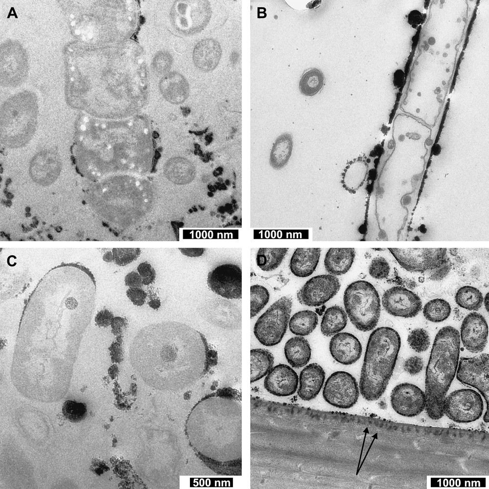
TEM images showing the different bacterial–mineral associations. (A) Image taken showing a large multi-chambered filamentous bacterium with a small amount of mineral formation close to the membrane. (B) Image of a possible sheathed-type bacterium. Here the black-coloured iron oxides lie in a straight line on the bacterium's boundary, with larger round deposits found randomly along the line (sample with osmium). (C) Image of a number of bacteria, two of which exhibit internal, electron-dense structures in addition to extracellular mineral deposition. Also in this section are bacteria not associated with minerals, and minerals found not associated with a bacterial membrane. (D) Image of the cuticle–bacteria boundary. Here we can see very small, thin discontinuous layers of iron oxide around a number of the bacteria. Of particular interest here is the mineral deposited into the cuticle in the bottom half of this image. The two black arrows point out some examples of the iron oxide infiltrating the cuticle. Additionally, one can see liquid crystalline-like organisation of the cuticle, which has already been described by Bouligand [41].
Larger, filamentous, chambered bacteria are observed to lack an association with mineral precipitates (with only one exception to date, see Fig. 1A), due perhaps to their protection by surrounding thick polysaccharide or proteinaceous layers. In addition to the extracellular iron oxide precipitates, internal granular electron-dense structures are present within numerous smaller bacteria (Fig. 1C). Another area of iron-rich oxide precipitation, in close vicinity to the location of the bacteria, is the inner surface of the branchiostegite cuticle. This surface is pitted, and an electron-dense mineral has been precipitated in the pits (Fig. 1D). Whether this is merely a chemical precipitate is unclear, as it is possible that neighbouring bacteria or any organic coating on the cuticle surface may be influential. Aside from the precipitation around bacteria, deposits are found in other locations, taking elongate forms comprised of smaller conjoined rounded aggregates. The difference in electron density observed in TEM and, in turn, shade of grey of the minerals are suggested here to be related to the iron content, i.e. a grey colouration denotes relatively low iron content, and so likely early stage oxide deposition.
3.1.1 Mineral associations with small-sized bacteria
Focussing particularly on the most significant bacteria (morphotype 3) with regard to associated mineralization, we observe three main relationships (Fig. 2). These are: (1) a close association between the bacterial membrane and mineral–here, there is no visible space between the precipitate boundary and the outer bacterial membrane (Fig. 2A and B) – (2) zoned mineral deposition (Fig. 2C and D); and (3) a distant bacterial membrane to mineral association, where there is significant distance between the precipitate boundary and the outer bacterial wall (Fig. 2E and F). Of these three relationships, the first association was the most frequently observed, in approximately 70% of the observed iron oxide encased bacteria.
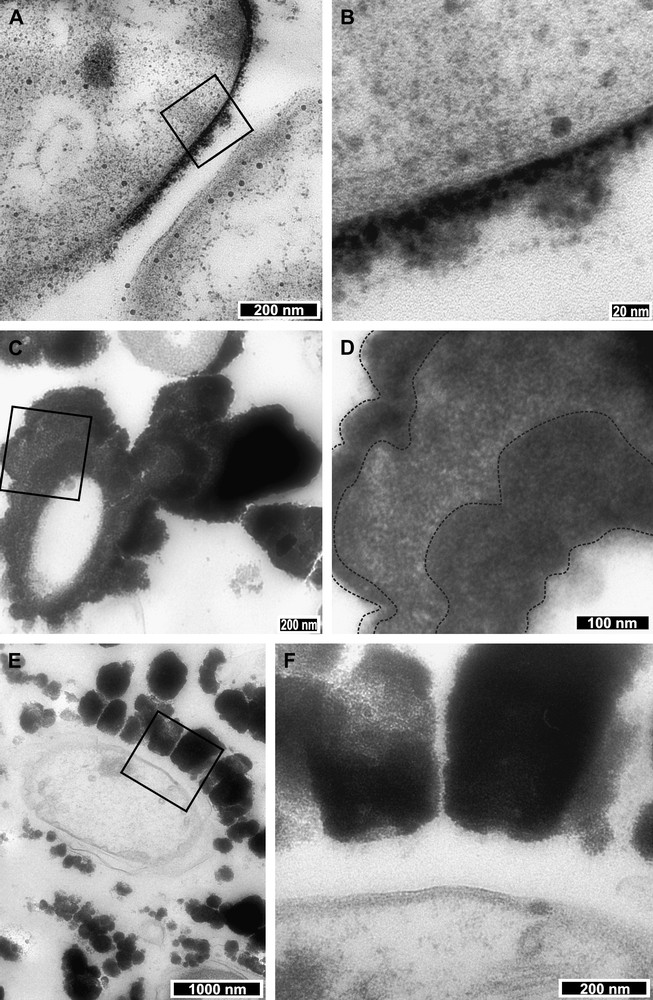
TEM images highlighting the three main bacteria–mineral relationships. (A) Image showing a bacterium surrounded by a layer of amalgamated microscopic rounded mineral deposits. The minerals and bacterium show a very close relationship; mineral(s) have grown directly on the bacterium membrane. The black square shows the location detailed in B, a zoom-in (100 000×) on an area where the membrane and minerals appear to touch. Note the rounded granules of mineral that comprise the surrounding deposits. (C) Image showing a bacterium that is highly mineralized to the point that very little bacterial structure is visible. Additionally, the mineral deposits exhibit layering or zoning. The black square drawn on C highlights the location of D, which shows these layers in more detail. Black lines on image D (taken at 40 000×) show the potential extents of the different layers. (E) Image showing a distant relationship between bacterium membrane and mineral. The black square on E shows the location of image F (taken at 20 000×), a zoom on the interface between mineral and bacterium.
Fig. 2A and B illustrates a close bacteria–mineral relationship. Fig. 2A shows two bacteria, the one to the left exhibiting immediate mineral precipitation on the outer membrane, whereas the bacterium on the right hand side shows the early stages of oxide deposition. Close examination of the interface between the mineral and membrane reveals that the bacterium is coated by an amorphous, particulate iron oxide with a clear interior edge of higher electron density (Fig. 2B). Maximum mineral thickness on this example is 45 nm.
The second bacteria–mineral association, zoned mineralization, is illustrated in Fig. 2C and D. Here, slight differences in electron density (grey to black colouration) potentially denote different layers or zones in the Fh deposit. In Fig. 2C the potential zone boundaries are highlighted by a dashed line overlay. In this image, the layer thickness ranges from a minimum of 115 to >175 nm, as the layers are irregular and petal-like in section.
The third association is one where there is a significant distance between the bacterial membrane and the start of iron oxide deposition. Fig. 2E illustrates one such example, which, when imaged in greater detail (Fig. 2F), reveals the outer bacterial membrane separated by a minimum space of 135 nm from ‘teeth-like’ iron oxide deposits. The inner surfaces of these mineral growths appear to be slightly indented in the potentially secreted protein material around the bacterium. These ‘teeth-like’ deposits suggest that, in comparison to the more continually layered mineral–membrane associations, the mineral here has undergone several separate point reactions that were sufficiently spaced to start the growth of separate iron oxide features.
Generally, all the iron oxide deposits examined by TEM appeared very friable and amorphous. The small particles (≤1 nm) of iron oxide appear to join or grow together to form larger spherical aggregates (≥2 to 300 nm), which in turn grow over time to form more continuous layers around the bacteria. However, such an observation cannot be accepted as definitive given that it has been made from two-dimensional (2D) images. Hence, we undertook a 3D investigation into the ferrihydrite distribution around the bacteria.
3.2 Distribution of principal ferrihydrite elements around a bacterium
In order to image the true distribution of ferrihydrite deposits, and try to gain insight into their origin, we analysed the two primary elemental constituents of the precipitates (iron and oxygen) using EFTEM. Fig. 3 shows the results obtained for one representative bacterium with both a close membrane–mineral relationship and potentially-zoned mineral deposition. Fig. 3A and D show the data relating to oxygen and Fig. 3C and E show those relating to iron. Fig. 3B shows a TEM zero-loss image of the analysed bacterium, with clearly darker, more electron-dense areas that can be interpreted as partial layers. PEELS analyses, shown in Fig. 3D and E, confirm the presence of both oxygen and iron, with the oxygen peak at 535 eV, and iron peak at 708 eV. Fig. 3A and C presents the ESI results, with the filtered 3-energy window analyses for oxygen and iron overlaid onto a High-Contrast Image (HCI – taken at 250 eV), showing the 2D elemental distribution in the oxide precipitates. It is clear from this that oxygen and iron co-occur where the elemental signals are strongest. The iron signal is stronger and more densely distributed than that of oxygen, but both element signals are found at highest concentration immediately next to the bacterium. There is a slightly weaker element signal for both elements in a second discontinuous layer ∼50 nm further out from the outer edge of the layer nearest to the bacterium.
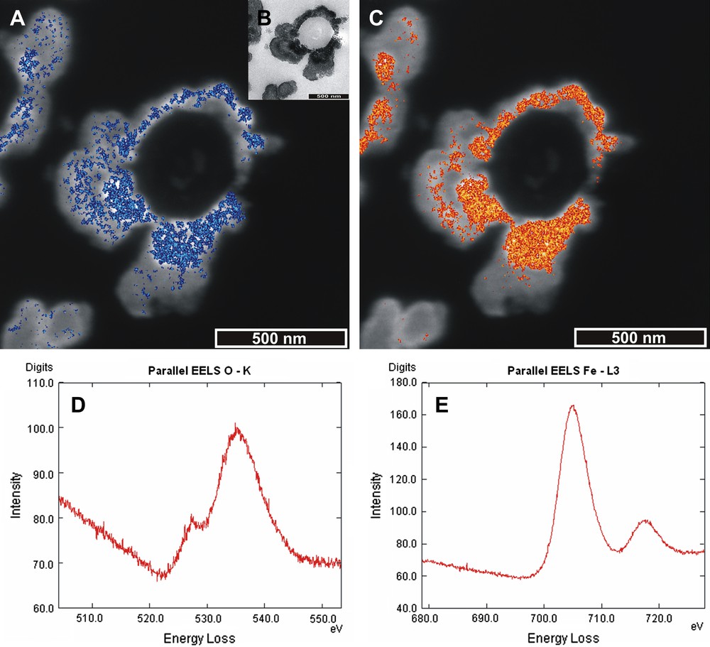
EFTEM results for elemental analysis of oxygen (blue) and iron (red). (For interpretation of the references to colour in this figure legend, the reader is referred to the web version of this article.) (A) High Contrast Image (HCI) taken at 250 eV of a bacterium surrounded by layered deposits with an overlay in blue of the location of the element oxygen from a three-energy window analysis method. The oxygen signal is most dense in areas of light blue. (B) TEM image of mineral coated bacterium clearly displaying layered surrounding deposits. (C) HCI taken at 250 eV with iron element signal overlay in red and orange. Element signal densest in orange areas. (D) Supportive spectrum for presence of oxygen. Note the double peak with maximum at 535 eV. (E) Supportive spectrum for the presence of iron. Note the characteristic double peak, with a maximum of 709 eV.
The ESI analysis images the strongest elemental signals for iron and oxygen, and so does not show results for the full range of elemental signal strength. Therefore, it is likely that both iron and oxygen are to be found at lower concentrations inbetween the two main areas of high iron and oxygen elemental signal.
3.3 3D imagery of a bacterium–mineral association
The main aim of this study was to produce animated 3D reconstructions of the ferrihydrite coating around bacteria found in the branchiostegite of the hydrothermal vent shrimp R. exoculata. Collection of angled zero-loss series on an EFTEM provided a reliable view of the distribution of iron oxides around the bacteria, including the representative bacterium discussed here.
Fig. 4 shows raw images, collected at varying degrees, of an example of the most frequently observed bacteria–mineral association (Type 1, Section 3.1.1). Here, one observes a thin grey layer that appears to be comprised of amalgamated, friable, amorphous particulate matter. In addition to its extracellular mineral deposits, the bacterium contains an electron-dense granule, the same type of which was mentioned in Section 3.1. After alignment, normalisation and reconstruction of the tilt series, the bacterium could be viewed in 360°. The inner and outer surface of the surrounding oxide is clearly visible, along with the internal granular structure (Fig. 5). 3D reconstruction reveals that the mineral layer around the bacteria appears to be an interconnected network of particulate aggregates, exhibiting a pseudo-linear form running parallel to the bacterium's long axis. However, this may be an artefact from incomplete information recovery (missing wedge) due to the impossibility of obtaining full tilt series (−90° to +90°) on a TEM. What is clear is that the 3D reconstruction gives a much better idea of the “less-than perfect” surrounding mineral layer.
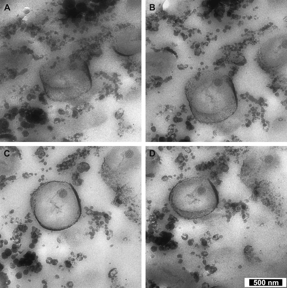
Four images from a tomography tilt series taken at 8000× using a LEO-912 Omega Ω. Tilt angles A = −50°, B = −28°, C = +25° and D = +50°.

Frames grabbed from a 3D reconstruction volume video realised using Chimera software [27]. Images A–F show a progression through a simple rotation of 180° about a horizontal axis. Video caption 3D visualisation of a bacterium exhibiting a close association with Fh mineral (white coloured material). This bacterium not only shows extracellular mineralization, but also an intracellular granule structure. The 3D animation shows the inner and outer surfaces of the Fh deposit around the bacterial membrane about both the x and y axes.
4 Discussion
The microbial precipitation of ferrihydrite is widespread in nature, where bacteria act as templates for iron deposition [28]. Iron hydroxides like those seen around the bacteria in R. exoculata are known to occur both actively and passively, and although a few cases of enzymatic metal precipitation (i.e. active precipitation) have been demonstrated, biological responsibility for Fe deposition is hard to prove as the iron-depositing bacteria are difficult to cultivate in the laboratory. It must be noted, however, that strains of neutrophilic iron oxidisers (with very close associations with iron oxides) have been successfully isolated and described following studies on the Loihi Seamount hydrothermal vents [12] and in the Juan de Fuca deep-sea hydrothermal area [29]; therefore, cultivation of the bacteria within the shrimp gill should be possible. Mineral formation on bacteria is generally not controlled by the organism; it occurs because of the physicochemistry of the bacterial surface and the chemistry of the cell's environment [30]. It is suggested to follow two steps. In the first, metal ions in the aqueous surroundings of the cell interact with the overall negatively charged groups (carboxyl, phosphoryl and amino groups) in the surface structures, producing an electrostatic charge complementation between the charged groups in the cell polymers and the metal ions. Subsequently, the presence of bound metal ions in the wall lowers the activation energy required for further metal deposition [30]. Presumably, these two steps can occur both actively and passively. Here we are trying to establish whether the epibionts found in the gill chamber of R. exoculata are actively or passively depositing Fh. Of note is that actively metabolising bacteria, with highly energised plasma membranes, can inhibit mineral formation as the cell wall is flooded with protons, which in turn compete with metal cations [31]. This is the reason why passive precipitation of metal oxides is often seen in association with dead bacterial organics [28]. Additionally, these mineral encrustations/precipitates would normally be seen as potential inhibitors of growth and bacterial surface reactions; therefore, one can propose that the bacteria must benefit from the precipitation of Fh in some way.
Bacteria as a group have the highest surface area to volume ratio of any group of living organisms [32]. This, along with the presence of charged chemical groups on cell surfaces, is responsible for their potent mineral-nucleating ability [30]. The bacterial cell surface polymers contain functional groups (i.e. carboxyl, phosphate) that are highly reactive and facilitate the absorption of dissolved metals [33]. As previously stated, the main volume of Fh is found in association with small, rod-shaped bacteria at the moment attributed to one single bacterial phylotype of the ɛ-Proteobacteria [3]. One can suggest a very simple reason for the mineralization occurring preferentially around the smaller bacteria, and that is their larger surface area in comparison to the filamentous and sheathed bacteria. As such, these smaller bacteria play a major part with regards mineral accumulation in the shrimp's brachial chamber, and may have an integral role in energy production for R. exoculata.
4.1 Mineral associations to the smaller bacteria
We have identified three main bacteria membrane–mineral associations: (1) directly touching, adjacent (close), (2) potentially-zoned, radiating petal and (3) separate, non-contact (distant). All of the relationships can either be determined by the bacteria's influence on its surrounding environment, its metabolic function, and/or the nature of its exterior membrane. Bacteria with the close mineral association show precipitation directly onto the outer membrane. This relationship makes it reasonable to speculate that these bacteria have a more active role in Fh production. However, this cannot be tested or proved without culturing the bacteria. The bacteria with potentially-zoned mineral associations suggest that precipitation occured over a longer period of time with modulative intensity. The radiating, petal-like zones may not simply represent mineral precipitation from iron-rich fluids of varying intensity passing through the gill chamber. Instead, the elevated electron density and, in turn, iron content could be attributed to additional ferrous iron being absorbed onto oxyhydroxide surfaces, in the same way as observed experimentally by Chan et al. [34]. Additionally, these radiating, petal-like zones may represent sections through a twisted rope-like form, similar to that produced by the bacterium Gallionella ferruginea [35,36]. Bacteria exhibiting distant mineral associations are potentially sheathed bacteria (e.g. Fig. 1B), surrounded by a protective layer of proteinaceous/polysaccharide material. As briefly discussed previously, the associated mineral deposits have a ‘tooth-like’ morphology, each Fh ‘tooth’ being clearly and smoothly separated from its neighbours. The ‘teeth’ do not appear to be products of simple mineral fracturing during sample preparation, as their smooth edges attest to. Instead, we suggest that they represent reactions with points on the sheath that are sufficiently far apart so that the deposits never joined together. Alternatively, considering that the Fh appears to sink into the bacterium's proteinaceous surround, the ‘teeth’ may in fact be separated from one another by proteinaceous material. However, perhaps this association is a chance find in this section, and further down the length of the bacterium the relationship is different, and the Fh ‘teeth’ join together to form an irregular layer.
4.2 Iron and oxygen distribution
The EFTEM study clearly shows a much larger, denser, compact signal for iron compared to oxygen, and also that the elemental signals co-occur in 2D. We suggest that the layer of high signal strength for iron and oxygen is found in close vicinity to the bacterial membrane, due to the microbe's influence on the precipitation process. A second band of high elemental signal may be explained as the result of a separate pulse of microbially-steered precipitation, or as a horizon where microbial-influenced precipitation gives way to chemically driven precipitation. This could be due to a change in the chemistry of the fluid entering the branchiostegite to a relatively iron-richer fluid, or as a horizon of ferrous iron absorption by the oxide deposit. The iron-rich fluid, presumably diluted iron-rich vent fluids, is continuously replenished by the beating of the shrimp's gill. However, due to the structure of the gill chamber, and interaction with the shrimp's soft parts, turbulent eddies are likely to be formed in the fluid flow, perhaps allowing for a slightly longer reaction time.
In summary, the close association of the high concentrations of iron and oxygen in the deposit to the bacterial wall suggests the Fh to be microbially mediated, even if this is not an ‘active’ but ‘passive’ process. Owing to the relatively large analysis area compared with the very thin layers of iron oxide precipitate, quantitative elemental data cannot be acquired via EFTEM. Such studies would require a technique such as X-ray nanoanalysis to better evaluate small-scale elemental fluctuations through the precipitate layers (both laterally and radially), in the search for indicators of ‘active’ bacterial–mineral precipitation.
4.3 3D bacteria–mineral associations
Reconstructing the 3D relationship of the Fh to the bacterial membrane has provided us with a better understanding of how the deposits are arranged on the bacterial surface (see video of 3D reconstruction). The Fh texture seen here is consistent with bacterially mediated mineral deposition. The Fh has an amorphous, particulate texture, with small particles (≤1 to 10 nm) joining to form elongate and globular aggregates around the bacterium. They form an irregularly networked deposit. Intracellular granules exhibit the same structure and are suggested to represent energy reserves or reservoirs of structural building blocks [37]. Such granules are not unusual in bacteria, and tend to be separated from the cytoplasm via a lipid membrane, as observed in iron-reducing bacteria by Glasauer et al. [38]. In the case of reduced hydrothermal venting, only the reduced fraction of iron (Fe (II)) in ferrihydrite or the absorbed Fe (II) can be used as an electron donor and oxidised with oxygen to gain energy. Ferric iron (Fe (III)) can serve as an alternative electron acceptor in oxygen-depleted environments, but this should not be the case in the relatively well-oxygenated shrimp environment. However, should the shrimps' environment become oxygen-depleted, the granules may act as an emergency energy source until the shrimps' find an alternative.
The poorly crystalline nature of the iron oxide is similar to that seen in association with gastropods encased in oxide nodules from vent sites in the Manus Basin, where precipitation has been mediated by an organic outer layer and the presence of microbes [39]. It has been suggested that if the precipitation process within the gill chamber were being merely driven by a chemical reaction, the time for a precipitate to develop could be too long, with a half life for Fe (II) around 35 h in the shrimp environment, compared with a couple of minutes in 25 °C oxygenated seawater [2]. Hence, the slower the chemical reaction, the longer the ferrous species remain in solution, allowing bacteria to compete successfully to take over the oxidation process [40]. Therefore, it is likely that the ferrihydrite precipitation seen in R. exoculata is indeed catalysed by the presence of microbes, but it remains unclear from this work whether the precipitates are ‘actively’ formed by the bacteria.
5 Conclusions
Our results provide important new information on the 3D distribution of the Fh around the shrimps' epibionts. The 3D distribution of the minerals around the bacteria has not provided undisputable evidence for ‘active’ mineral depostion by the bacteria. However, the close associations observed certainly suggest that the bacteria are integral in the depositional process. From our work, we are able to propose two Fh deposition models. In the first model, Fh precipitation starts with point reactions on the cells' surfaces, resulting in spherical forms, which amalgamate to build a networked layer around the bacteria, until the reaction surface (membrane) is entirely covered. After this occurs, precipitation around a bacterium continues, but changes to a more chemically dominated process as the activation energy is lowered. The alternative (second model) is that all precipitation is chemically driven and totally uninfluenced by the bacteria. The first model is preferred because it offers a more fitting explanation for the presence of very large numbers of bacteria in the shrimps and their close association with Fh deposits.
In order to address questions regarding the bacteria's role, future work will comprise high-resolution chemical analyses, to look at nanometre-scale radial and lateral changes in iron and its associated elements in the bacterially associated Fh deposits. This work may highlight important subtle variability in the concentration of iron with distance from the cell. However, other tools such as culturing the bacteria and iron isotope analysis, which are either currently unsuccessful or unavailable for use at this small scale, would provide definitive answers. We suggest that the bacteria's role may be integral to the shrimps' well-being in these extremely toxic environments, and not that the bacteria merely colonise a protected, less extreme habitat inside the shrimps. Certainly, the chemical environment at the Rainbow hydrothermal vent site, with its iron enriched fluids, supports the suggestions made here that iron represents a viable energy source. This is in favour of the hypothesis proposed by Zbinden et al. [2].
Acknowledgements
The authors would like to thank the Monitoring Mid-Atlantic Ridge (MOMARnet) European Project for funding this postdoctoral work (contract MRTN2004505026). Additionally we thank the University Pierre-et-Marie-Curie (UPMC) for hosting this work, and the ‘Service de microscopie électronique’ (SME, Institut de biologie intégrative, UPMC) for the use of the LEO-912 Ω. Additional thanks go to Dr. Graeme Eagles, Dr. Florence Pradillon, Dr. Juliette Ravaux, and Miss Caroline Schmidt for their support and input.