

1 Introduction
Dye-sensitized solar cell (DSSC) is a prospective alternative to the conventional silicon solar cells for its low cost and high efficiency [1–3]. The conventional DSSCs consist of TiO2 nanoparticles, sensitizers, redox electrolytes and usually the platinum (Pt) counter electrode. For the conventional liquid electrolyte DSSCs, problems such as easiness to evaporate, corrosion and leakage of the liquid electrolyte bring limitations to practical applications [4,5]. Many alternative materials were experimented to replace the conventional liquid electrolyte, such as room temperature ionic liquids [6], solid and quasi-solid composite polymer electrolyte [7,8], gel electrolyte[9,10], organic and inorganic hole-transport materials [11–14].
Poly(ethylene oxide) (PEO) based composite polymer electrolyte (CPE) was intensively studied for quasi-solid state DSSCs. The redox couple moved in the free-volume and amorphous phase of the polymer matrix to make the DSSC work [7,15]. The ionic conductivity and the penetration of the polymer electrolyte into the porous TiO2 electrode are the focus of studies to improve the performance of the DSSCs [15]. Liquid plasticizers like low molecular weight organic solvent propylene carbonate (PC) and ethylene carbonate (EC) [16] or low molecular weight polymers such as poly(ethylene glycol) [17] and solid plasticizer succinonitrile [18,19] were introduced into the CPE to decrease the glass transition temperature of the polymeric matrix and increase the polymer chain mobility, so the ionic conductivity of the CPE and the performances of the DSSCs were improved.
In our previous work, a lithium salt lithium bis(trifluoromethane sulphone)imide (LiTFSI) was introduced into the PEO/P(VDF-HFP)/SiO2 composite polymer electrolyte as a plastic salt [20]. The LiTFSI which has a large and irregular shaped N(SO2CF3)2− anion is reported as a plasticizer increasing the ionic conductivity of the polymer electrolyte [21,22]. Here, the function of LiTFSI is compared with the conventional salt LiClO4 to illuminate the difference between the anions. The ionic conductivity and the polymer conformation change are checked. Comparison of the DSSCs performances with LiTFSI and LiClO4 modified CPE together with electrochemical impedance spectroscopy measurements indicates the special function of LiTFSI.
2 Experimental
2.1 Materials
LiTFSI and LiClO4 (Acros, analytically pure); TiO2 nanoparticles(P25, 20–30 nm, Degussa AG, Germany) and SiO2 nanoparticles (Aerosil 200, 12–15 nm, Degussa AG, Germany); PEO (Poly(ethylene oxide), molecular weight Mw = 2 × 10⁶, Aldrich); P(VDF-HFP) (Poly(vinylidenefluoride-cohexafluoropropylene), Mw = 4.77 × 10⁵, Elf Atochem); Propylene Carbonate (PC) and 1, 2-dimethoxyethane (DME), analytically pure; LiI (Across), I2 (Beijing Yili chemicals, China), N719 (Zhongsheng, China).
2.2 Preparation of the LiTFSI modified CPE
First, 0.2 g high molecular weight polymer compound PEO/P(VDF-HFP) (weight ratio 2:3) and 6 g organic solvent PC/DME (volume ratio 7:3) were blended at 80 °C for about 4 hours [23]. Then 0.2 g LiI and 0.038 g I2 were added to the slurry under continuous stirring. The obtained sample is noted as O. To investigate the effect of the LiTFSI salt on the performance of the DSSC, LiTFSI was further added to the original samples with LiTFSI:LiI molar ratios of 0.116:1 (noted as sample T1), 0.232:1(T2) and 0.348:1 (T3), respectively.
For comparison, another lithium salt LiClO4 modified CPE electrolyte was prepared following the same procedure. Three different molar ratios of the LiClO4 to LiI were 0.116 (C1 sample), 0.232 (C1) and 0.348:1 (C3), respectively, which are the same with the LiTFSI:LiI.
2.3 The DSSC fabrication
The TiO2 (P25) nanoparticles were dispersed in alcohol to prepare the precursor for the TiO2 nanocrystalline photoanode [24]. After sintering the TiO2/FTO at 450 °C for 30 min and cooling down to 80 °C, the photoanodes with a thickness of 12 μm were immersed in the N719 dry ethanol solution overnight to complete the dye sensitization process.
The dye-sensitized nanocrystalline TiO2 photoanodes were baked in the oven at 80 °C for a few minutes to eliminate the water in the pores of the nanoparticles. Then the polymer electrolyte was dropwise added to the dye-sensitized TiO2 photoanodes, and then it was put into the oven at 80 °C to evaporate the redundant organic solvent in the polymer electrolyte. After 2 hours, the sputtered Pt counter electrode was pressed tightly on the polymer electrolyte by a clip.
2.4 The measurements
The ionic conductivities of the original and salt modified polymer electrolytes were measured using the Pt/polymer electrolyte film/Pt sandwich type electrode structure. Agilent 4294A precision impedance analyzer (USA) was used to measure the impedance (Nyquist plot) of the polymer electrolyte. A perturbation voltage of 10 mV was applied over the frequency range 40 Hz to 1 MHz. The ionic conductivity, σ, of the membrane was calculated from the following equation: σ = L/ARb, where L is the thickness of the polymer electrolyte membrane, and A is the area of the electrode. The resistance (Rb) was taken at the intercept of the Nyquist plot with the real axis [25]. The temperature dependence of the conductivity of the polymer membrane was measured in a Bench-Top Type Temperature and Humidity Chamber (Espec Corp, Japan) over the temperature range of 303 K to 353 K.
Differential scanning calorimetry (DSC) thermograms of the polymer electrolyte membranes were measured with a Perkin Elmer DSC instrument at a heating rate of 10 °C/min under nitrogen atmosphere and over a temperature range of approximately −120 to 20 °C. The attenuated total reflectance FTIR (ATR-FTIR) spectra were collected by adhering the CPE to the Ge window and scanning from 4000 to 400 cm−1. The scanning electron microscope (SEM, Hitachi SU-70, Japan) was used to examine the cross-section structure of CPE/TiO2 nanocrystalline interface.
The electrochemical impedance (EIS) measurements CPE type DSSCs were carried out with the CHI electrochemical workstation under a frequency range of 0.05–100 kHz and a perturbation voltage of 10 mV. The CPE type DSSCs were measured in a dark environment with a forward bias of −0.68 V.
For photoelectrochemical measurements, a 1000 W xenon light source (Newport, USA) was used to give an irradiance of 100 Mw/cm2 (1 Sun, AM1.5). The light intensity was calibrated by a Si-1787 photodiode (spectral response range: 320 to 730 nm). A Keithley 2400 digital source meter unit (USA) was used to measure the current–voltage curves under the light. The active DSSC area was controlled at 0.16 cm2 by a mask.
3 Results and discussions
3.1 The ionic conductivity of the CPE with addition of LiTFSI and LiClO4
The mechanism of the ionic conductivity of the salt in composite polymer electrolyte is the ions move in the free-volume and amorphous phase created by the long polymer chains. The type and the content of the ions in the polymer matrix influenced the ionic conductivity a lot [16,26].
Fig. 1a exhibits the ionic conductivity change with the different LiTFSI contents at 303 K. For comparison, the ionic conductivity of LiClO4 is also indicated. With increasing the content of LiTFSI or LiClO4, the ionic conductivity enhances a lot at T1 and C1 (LiX: LiI = 0.116:1), then suffers a decrease with more salt added.
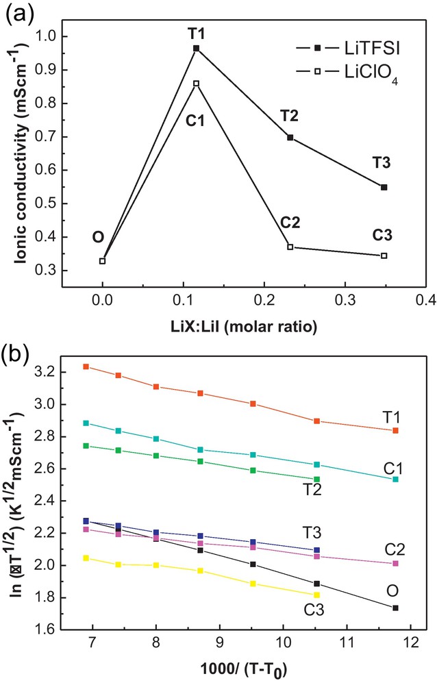
a: the ionic conductivity of the LiTFSI and LiClO4 modified composite polymer electrolyte at 303 K; b: the ionic conductivity as a function of temperature with different CPE fitted in Vogel-Tamman-Fulcher (VTF) equation.
The LiI in the unmodified CPE is Li:O = 1:1.3 in molar ratio. When a small amount of LiTFSI or LiClO4 is added (LiX:LiI = 0.116:1) and dissolved, the CPE exhibits a large increase of the ionic conductivity. When more salt is added, the ionic conductivity does not increase anymore, which may be due to the high degree of ionic aggregation at the high salt content [27]. Compared with the LiClO4, the LiTFSI system has higher ionic conductivity in the polymer matrix. It implies that TFSI− ions influence the ionic conductivity of the CPE differently from ClO4−.
The relationship between the ionic conductivity and the temperature is expressed by fitting the Vogel-Tamman-Fulcher (VTF) equation:
| (1) |
In the temperature range measured, the LiTFSI system exhibits higher ionic conductivity than the LiClO4 system. In our case, the PEO/P(VDF-HFP) is the polymer matrix where the ions move in the free-volume and amorphous phase created by the long polymer chains. With adding the LiTFSI or LiClO4 salt, the salt is dissolved and interacted with the polymer chain to influence the ionic conductivity. LiTFSI has (CF3SO2)2N− anion which is reported to be highly delocalized and makes the salt easily dissociated in polyether-based electrolytes [21,28]. So the better dissociation of the LiTFSI may be one reason of the higher ionic conductivity than in the case of LiClO4. On the other hand, the interaction of the dissolved ions with the polymer chain is another reason of the ionic conductivity change. The interaction of the salt with the polymer matrix is investigated by FTIR spectra and DSC thermograms.
3.2 ATR-FTIR spectra
In our previous work, the function of LiTFSI to increase the ionic conductivity is analyzed. Here, the LiTFSI is mainly compared with the conventional salt LiClO4 in Fig. 2. In the ATR-FTIR spectra of LiTFSI modified CPE, the new vibrations of –SNS-(795 and 739 cm−1), –SO2(1352 and 1054 cm−1), –CF3(1173 cm−1) are indicated [20]. There are some changes after the salts’ modification. Firstly, the CH2 vibration bands at 2880, 2910, 1490, 1454 and 1237 cm−1 show decreased intensity at T1 and C1 modifications. With further increasing the salt amount, the vibration bands become obvious again. Secondly, the double peak at 951 and 933 cm−1, which is the characteristic of the crystallized PEO, merges to a single one centered at 951 cm−1 at both T1 and C1 modified CPE and returns to normality at higher salts contents. It indicates that the crystallinity of the PEO polymer is suppressed when adding a small quantity of salt. [20,29]. It explains the increased ionic conductivity of CPE with C1 and T1 for a small modification of the salt content.
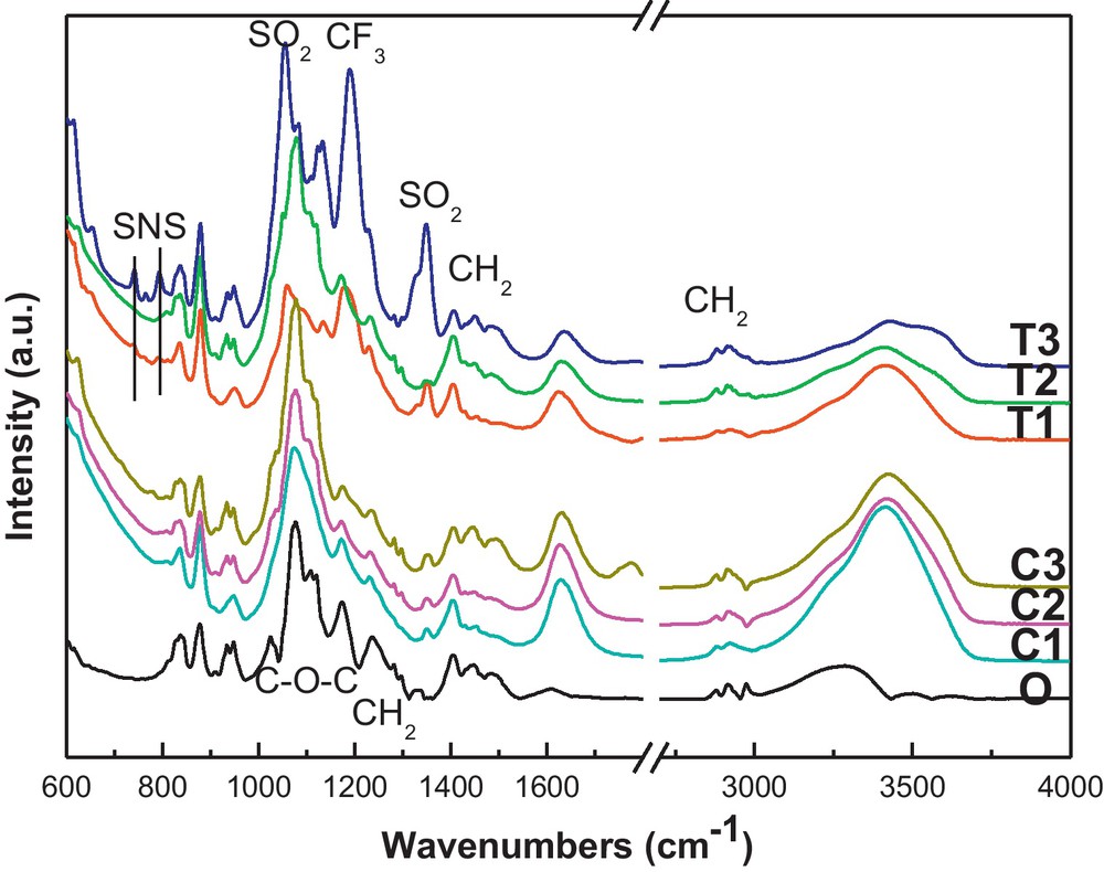
ATR-FTIR spectra of the original CPE (O), LiTFSI (T1, T2 and T3) and LiClO4 (C1, C2 and C3) modified CPE.
3.3 The DSC thermograms of the CPE
The LiTFSI has an anion with two strong electron-withdrawing groups(CF3SO2−), and the flexible nitrogen covalent bonds which are favorable to a lowering of the glass transition temperature Tg [21]. Tg was attributed predominantly to the motion of the polymer segment of the network according to the free-volume theory [30]. The change of the Tg can be used to explain the conformation change of the polymer chain. The glass transition temperatures of the LiTFSI and LiClO4 added systems are measured and taken at the inflection point of the DSC thermograms. The DSC thermograms are indicated in Fig. 3 and the Tg values of each CPE are indicated in Table 1.
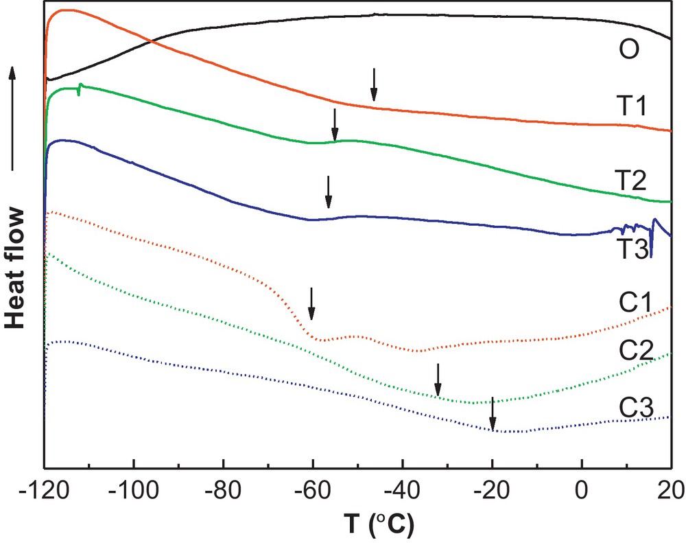
The DSC thermograms of the CPE.
The photovoltaic parameters of the DSSC with different CPE electrolytes (1 Sun, AM1.5). The glass transition temperature Tg with each CPE is also exhibited.
| Sample | Jsc (mA/cm2) | Voc (V) | FF | η (%) | Tg (°C) |
| O | 8.75 | 0.648 | 0.635 | 3.60 | −64.8 |
| T1 | 11.78 | 0.603 | 0.670 | 4.82 | −50.8 |
| T2 | 11.56 | 0.596 | 0.652 | 4.53 | −55.7 |
| T3 | 9.23 | 0.573 | 0.708 | 3.75 | −56.7 |
| C1 | 11.18 | 0.597 | 0.647 | 4.32 | −60.2 |
| C2 | 10.04 | 0.573 | 0.685 | 3.94 | −32.0 |
| C3 | 8.21 | 0.543 | 0.69 | 3.08 | −19.9 |
The Tg of the original CPE is taken at −64.8 °C following the previous report [23]. After adding the new salt in the CPE, the Tg increases for both the LiTFSI and LiClO4 modified system, which is due to the increased ion–polymer interactions [27]. However, the Tg change of the LiTFSI system is different from that of LiClO4 system. With the LiTFSI increase, the Tg enhances to −50.8 °C at first for T1 sample (LiTFSI:LiI = 0.116), then decreased to −55 °C and −56.7 °C for T2 and T3, respectively. In contrast, the Tg of the LiClO4 system increased with the LiClO4 content increase, that is, Tg increases from −60.2 °C for C1 sample(LiClO4:LiI = 0.116) to −32 °C and −19.9 °C for C2 and C3, respectively. The difference between the Tg changes in the two systems indicates the different conformation change of the polymer chains with the salts added. The reduced Tg with the LiTFSI content increase illustrates the large size and the chemical structure of the anion TFSI− makes the polymer chain easier to move, compared with the LiClO4 modification, whose anions are small and regular. So the LiTFSI acts like a plasticizer to decrease the Tg of the CPE.
The conformation change of the polymer host is one of the determinants of the ionic conductivity. With the LiTFSI added, it is dissolved and makes the polymer chain much easier to move compared with the LiClO4 salt. So the increased number of ions and the conformation change of the polymer chain both contributed to the higher ionic conductivity than that of the LiClO4 modified CPE as the Fig. 1 indicated.
3.4 The performance of the DSSC with LiTFSI and LiClO4 modified CPE
The cross-section structure of the T1 electrolyte on the TiO2 nanocrytalline is shown in Fig. 4. There are no apparent TiO2 nanocrystallines in the cross-section structure. It shows that the salt modified polymer electrolyte fine penetrated into the TiO2 nanocrystalline film, which guarantees the electron transport of the DSSCs (dye regeneration). The photovoltaic parameters of DSSCs with the LiTFSI and LiClO4 modified CPE at 1 Sun, AM1.5 are indicated in Table 1. And the J–V curves are expressed in Fig. 5. From the performances of the DSSCs, the Jsc values are improved with LiTFSI salt modified electrolyte compared with the original DSSC (Jsc = 8.75 mA/cm2). It is proved that the presence of lithium ions in the electrolyte can enhance the yield of exciton dissociation at the dye/titania interface, leading to the high photocurrent [31]. Here, the LiTFSI can provide the dissociated lithium cations and the TFSI− anions which made the polymer chain easier to move as is discussed above. It contributes to the fast movement of the redox couple and the improved Jsc. The Jsc reaches the highest value of 11.78 mA/cm2 with T1 electrolyte, then decreases as the LiTFSI concentration further increase, which is due to the higher content of LiTFSI, which did not help to increase the ionic conductivity as section 3.1 indicated.
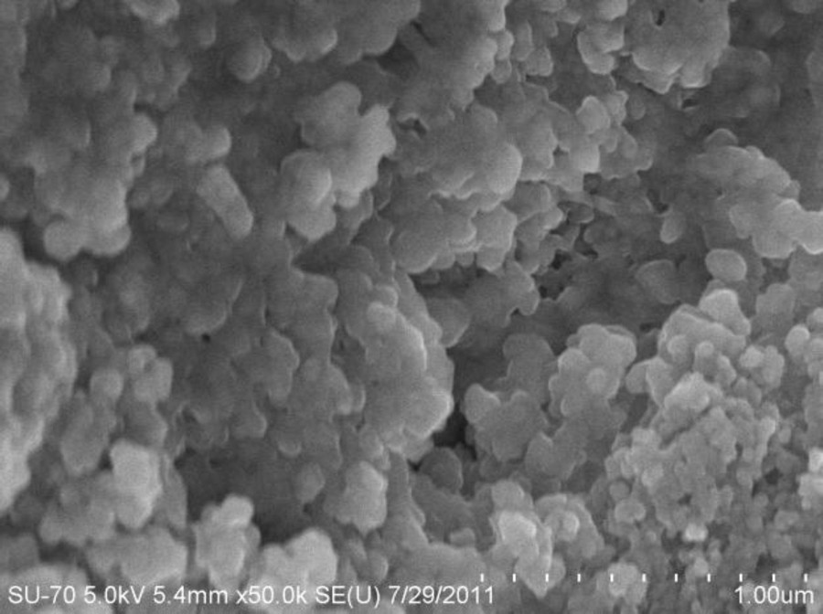
The cross-section structure of CPE/TiO2 nanocrystalline photoanode.
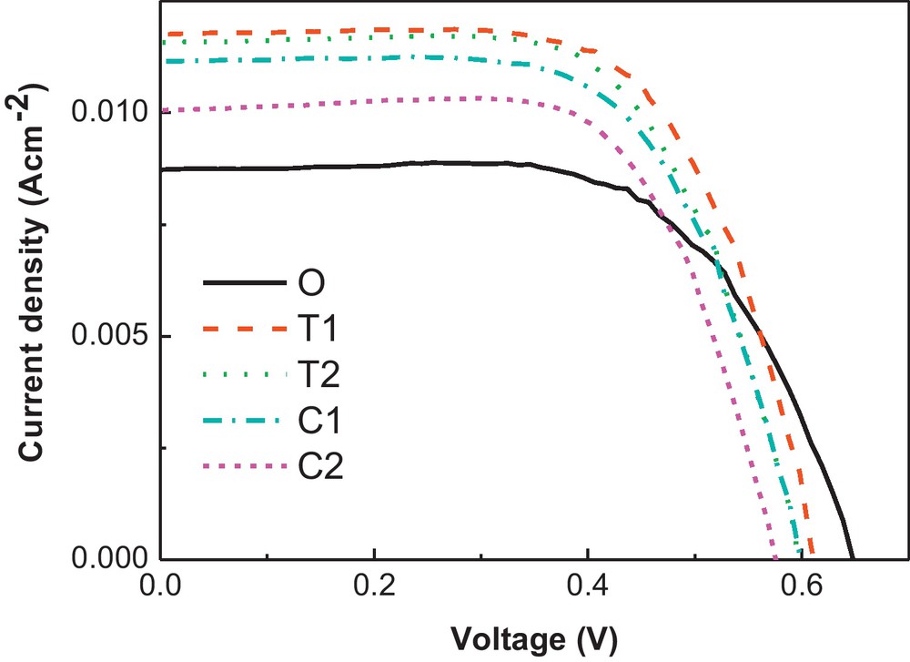
The J–V curves of the DSSCs with original electrolyte and the T1, T2, C1 and C2 electrolyte. Measured at 1 Sun, AM1.5.
However, Voc deteriorates with addition of LiTFSI. Voc is determined by the difference between the quasi-Fermi level of electrons in the TiO2 film and the energy of the redox potential of the redox couple in the electrolyte (EF,n–EF,redox). Addition of lithium ions can lead to more deep surface states below the conduction band edge to lower the EF of the photoanode, so the Voc of the LiTFSI modified electrolyte DSSCs decreased [31]. The performance of the DSSC with T1 electrolyte reached 4.82% (Jsc = 11.78 mA/cm2, Voc = 0.603 V and FF = 0.67), much better than 3.6% of the original DSSC (Jsc = 8.75 mA/cm2, Voc = 0.648 V and FF = 0.635).
In contrast to the LiTFSI modified system, the DSSC with LiClO4 modified electrolyte shows improved performance for the C1 electrolyte of 4.32% with improved Jsc and decreased Voc compared with the original DSSC. However, the Jsc and Voc are not as good as the DSSC with T1 electrolyte. Firstly, the salt plasticizer property of the LiTFSI makes the DSSCs with higher Jsc than the LiClO4 modified electrolyte; secondly, the TFSI− which has fluorine with large electronegativity is expected to reduce the recombination rate at the polymer electrolyte/photoanode interface in DSSC [27,32], so the Voc is higher for the LiTFSI modified DSSCs compared with the LiClO4 samples.
The electrochemical impedance spectroscopy (EIS) plots of the DSSCs with O, T1 and C1 electrolyte were investigated and expressed in Fig. 6. Under forward bias and dark environment, electrons are transferred from the FTO substrate into the TiO2 mesoporous network and react with I3−. At the same time, I− is oxidized to I3− at the counter electrode. The three semi-circles in the Nyquist plot are attributed to the charge transfer at the counter electrode, the electron transport in the mesoporous TiO2 film and the back reaction at the TiO2/electrolyte interface, and the ion diffusion in the electrolyte from high to low frequency range [33,34].

The Nyquist plots of the DSSCs with O, T1 and C1 electrolytes. The plots are measured in a dark environment under forward bias of −0.68 V.
The characteristic frequency in the middle-frequency semicircle of the Nyquist plot is inversely proportional to the electron lifetime (ω = τ−1) according to the EIS theory [33]. From Fig. 5, the original DSSC exhibits character frequency of ωmax = 2.61 Hz, corresponding to the electron lifetime of 0.383 s. The ωmax remains unchanged for the DSSC with T1 electrolyte; however, it increases to 4.64 Hz with the C1 electrolyte. So the electron lifetime of T1 is longer than C1. It confirmed that the LiTFSI in the CPE electrolyte is more efficient to prohibit the interface electron recombination compared with the LiClO4 modified electrolyte. So the Voc values of the DSSCs with T1∼T3 electrolyte are higher than with the corresponding C1∼C3 electrolyte.
4 Conclusions
In this work, the lithium salt LiTFSI is introduced to the CPE for the quasi-solid state DSSCs. Compared with the conventional salt LiClO4 modified CPE, the LiTFSI added CPE exhibited lower glass transition temperature Tg and the higher ionic conductivity. The two strong electron-withdrawing groups (CF3SO2−) and the flexible nitrogen covalent bonds made the LiTFSI salt easy to dissociate in the polymer matrix and the polymer chains are easy to move. The two reasons contributed to the better ionic conductivity of the LiTFSI than the LiClO4 in the CPE. With the addition of the LiTFSI:LiI = 0.116:1 in the CPE, the performance of the DSSC at AM1.5 increased to 4.82% with Jsc = 11.78 mA/cm2, Voc = 0.603 V and FF = 0.67, better than the 3.6% of the original DSSC with Jsc = 8.75 mA/cm−2, Voc = 0.648 V and FF = 0.635 and the 4.32% of the LiClO4 modified CPE with Jsc = 11.18 mA/cm2, Voc = 0.597 V and FF = 0.647. Furthermore, the TFSI− with electronegative fluorine atoms is more efficient to reduce the interface electron recombination in the DSSC compared with the ClO4−. So the DSSC with LiTFSI modified CPE exhibits higher Voc value than the conventional LiClO4 modified one.
Acknowledgements
This work is financially supported by National Natural Science Foundation of China (Grants Nos. 11004113 and 11074135), Natural Science Foundation of Zhejiang (Grant No. Y4090429). This work was also sponsored by Technology Innovative Research Team of Zhejiang Province (No. 2009R50010) and K.C. Wong Magna Fund in Ningbo University.