


 CC-BY 4.0
1. Introduction
In the context of addressing the challenges of climate change and energy crises, the energy storage and conversion industry is experiencing rapid growth. Many new synthetic chemicals are used in the production of electrochemical systems, making it a technology-intensive sector. Fluorinated organic and inorganic materials are widely used in electrochemical energy sources, including electrochemical storage devices (batteries, supercapacitors) and electrochemical conversion devices (fuel cells).
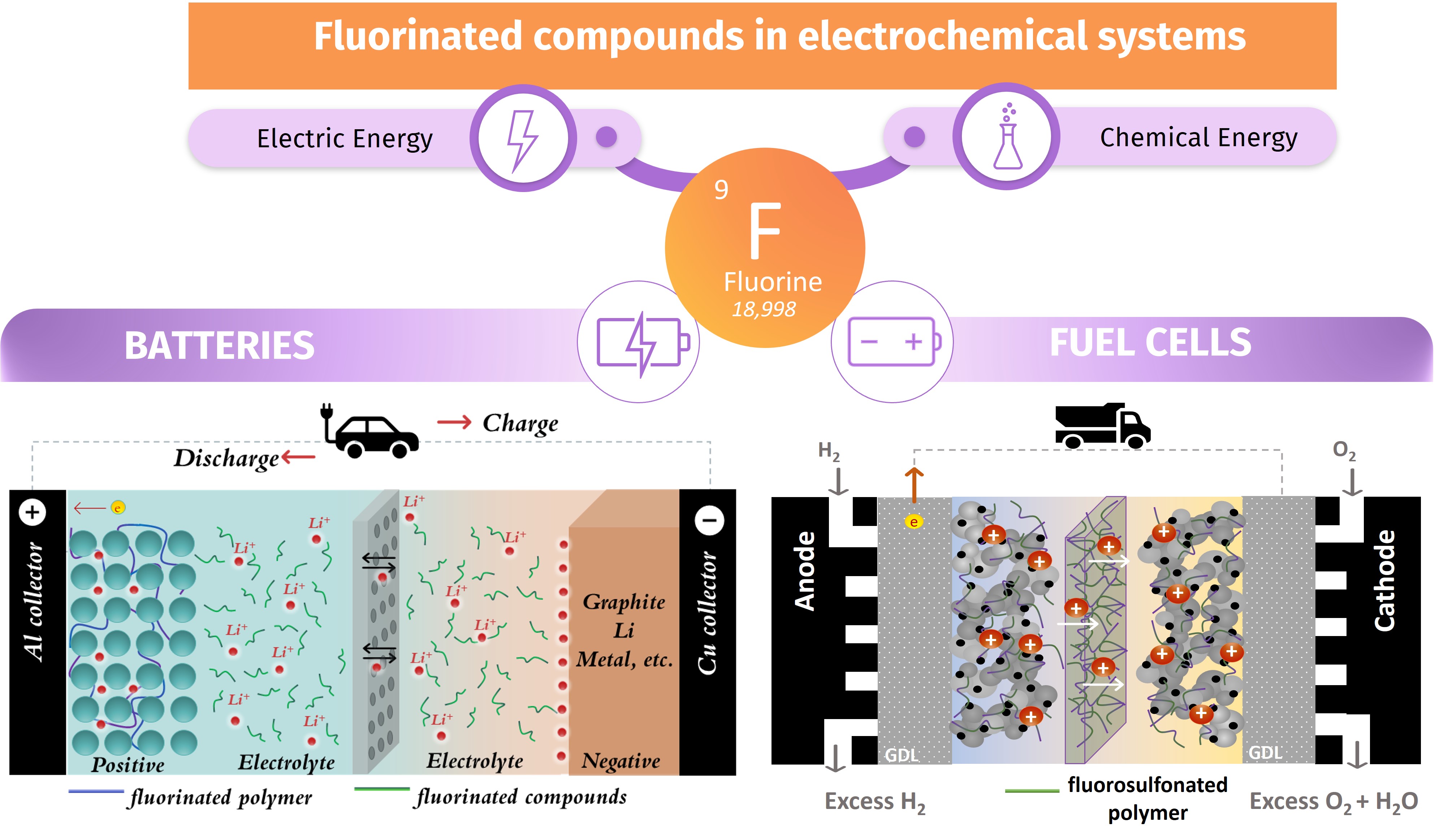
Rechargeable lithium-ion batteries (LIBs) are electrochemical cells that convert chemical energy into electrical energy. They have several advantages over other battery chemistries. For example, the voltage between their two electrodes is much higher, ranging from 3 to 4 volts, versus 1.5 to 2.2 volts for other batteries. This provides better performance in terms of energy and power density [1]. The battery consists of two electrodes: one positive and one negative An ion-conducting membrane separates them (Figure 1). In LIBs, both the negative and positive electrodes consist of composite electrodes, with materials such as graphite, iron phosphate, cobalt oxide, etc. These composite electrodes also contain carbon black, an electrolyte, and a polymeric binder. In between, a membrane is either a porous polymer separator filled with liquid electrolyte, or a dense ion-conducting polymeric film (sometimes swelled by a liquid electrolyte). It’s important to note that liquid-free electrolytes are used in all-solid-state batteries based on ceramic or polymeric electrolytes, allowing lithium metal (Li) to be used as a negative electrode.

Schematic representation of (left) a Li-ion battery (graphite as negative electrode) and (right) a Li-metal battery (Li metal as negative electrode). The main components containing fluorinated compounds are presented.
The key requirements for the materials used in electrochemical systems, such as electrolytes, separators, binders, etc., include high ionic conductivity, a wide electrochemical stability window, and good chemical and thermal stability [2]. Fluorine-containing organic compounds meet almost all of these requirements, especially high anodic stability. Currently, the recognized negative environmental impact of perfluoroalkyl and polyfluoroalkyl substances (PFAS) [3, 4] is offset by their positive effects on energy and power density, life span, and safety. Therefore, they still play an important role in the development of batteries.
In the Proton Exchange Membrane Fuel Cells (PEMFC), fluorinated compounds are of utmost importance in energy conversion systems. PEMFCs directly produce electrical energy by converting the chemical energy stored in fuels, such as hydrogen (H2) and methanol (CH3OH) [5, 6], with a low environmental impact due to their low or even zero greenhouse gas emissions (Figure 2a). It also has high theoretical (83%) and practical (∼50%) efficiency, making it the most developed and most promising fuel cell. The PEMFC requires low maintenance costs, thanks to its low operating temperature (around 80 °C) and quick start-up, which makes it suitable for a wide range of applications, from stationary use to electromobility. It is often used in hybrid form with LIBs [7].

(a) Schematic representation of a PEMFC. (b) PFSA, e.g., Nafion and its chemical structure and morphology.
In this system, the membrane, sandwiched between the two electrodes, allows protons to transfer from the anode to the cathode while preventing the transfer of reactant gases. Both electrodes contain binders and electrolytes based on perfluorosulfonic acids (PFSA), such as Nafion™ or Aquivion™. The advantages of these polymers come from their unique chemical structure, which is made up of a highly hydrophobic, chemically stable perfluorinated backbone, i.e., polytetrafluoroethylene (PTFE), and perfluorinated ether side chains that end in a sulfonic acid, i.e., a highly hydrophilic superacid. This structure induces a strong thermodynamic incompatibility between the backbone and side chain, which results in a specific nanoscale self-organization in the presence of water [8]. This, in turn, leads to the formation of well-defined nano-separated hydrophilic and hydrophobic phases and percolated nanodomains, as shown in Figure 2b for an example of Nafion.
The LEPMI has pioneered the development and application of lithium salts, polymer electrolytes, and the study of the impact of different commercial or homemade fluorinated or partially fluorinated compounds on the electrochemical performance of the system.
In this article, we have selected a few examples from among many others to illustrate the range of studied materials and their effect on electrochemical properties.
In a first part, we focused on the various components of lithium-ion batteries (binder, solvent, salt, polymer electrolyte). In the final section, we present briefly some alternatives to PFSA for use in fuel cells.
2. Lithium-ion batteries (LIBs)
2.1. Fluoropolymers as binders for composite electrodes
The binder material in electrodes, even though it is considered inert, plays a crucial role in maintaining structural integrity, improving interconnectivity within the electrode, enhancing adhesion to the current collector, and forming the solid–electrolyte interface (SEI) during the initial battery charging cycles [9, 10]. This polymeric binder must have excellent electrochemical stability and be compatible with the solid powders (active materials and conductive fillers), and also be insoluble in the electrolytes. Nevertheless, it must have a sufficient affinity for the electrolyte so that it is well impregnated, allowing the composite electrode to have good ionic conductivity. Fluorinated binders exhibit better electrochemical stability thanks to their superior resistance to oxidation compared to non-fluorinated binders [10].
The binders most commonly used today are based on PVdF (polyvinylidene fluoride) and its copolymers. Among these, PVdF–HFP poly (vinylidene fluoride-co-hexafluoropropene) is the most widely used. Since hexafluoropropene (HFP) cannot homopolymerize, its well-defined distribution along the chains must be spaced by the PVdF moieties. The PVdF and PVdF-based copolymers have excellent anodic stability and are used extensively as binders for various cathode materials. Due to the disorder caused by the inclusion of the HFP monomer, the crystallinity and melting temperature (Tc and Tm, respectively) decrease with increasing HFP concentration, while the glass transition temperature (Tg) increases. However, the stability of PVDF and PVdF-based copolymers in alkaline conditions is limited, where they undergo a dehydrofluorination reaction by successive elimination. Despite this instability, PVdF-based binders have been extensively used in composite negative electrodes. There is, however, a trend to replace them with carboxymethyl cellulose (CMC) [11]. In order to improve the interaction between the binder and the active electrode material, some copolymers bearing polar protic groups, such as PVdF grafted by vinyl phenol, were also used [12].
In composite electrodes, the goal is to maximize the content of active material, i.e., specific capacity, while minimizing the content of binder and conductive carbon. This must be done without compromising mechanical strength or electronic conductivity. This can be achieved by optimizing the performance of the PVdF binder, particularly its molecular weight distribution. Increasing Mw and Mn will improve both the mechanical strength of the composite electrodes and the binder’s adhesion to the active material and the carbon black.
2.2. Fluorinated organic solvent and porous separators
2.2.1. Fluorinated organic solvent
The conventional electrolytes used in LIBs are based on lithium salts dissolved in organic or polymer solvents. The basic function of an electrolyte is to transport ions while blocking electron conduction between the two electrodes. In the case of liquid electrolytes, the salts are typically dissolved in organic carbonate-based solvents, such as cyclic carbonates: ethylene carbonate (EC), propylene carbonate (PC), and linear carbonates: dimethyl carbonate (DMC), diethyl carbonate (DEC), etc. (Figure 3a). Cyclic carbonates (EC, PC) offer several benefits. They have a high dielectric constant, making it possible to use highly concentrated lithium salt solutions. However, they also have a high viscosity and melting point, especially in the case of EC. This can affect ionic conductivity. Therefore, these carbonates are typically mixed with linear carbonates, such as DMC, DEC, or ethyl-methyl carbonate (EMC), which exhibit lower viscosity and dielectric constants. This allows them to optimize the electrolyte’s properties. In addition to carbonates, electrolytes based on ethers or acetals are also widely used, especially in alternative battery systems. For example, dioxolane (DOL, acetal) and dimethoxyethane (DME, ether) are widely used in lithium–sulfur batteries. These low-viscosity electrolytes have good ionic conductivity, but they have low flash point Fp, low boiling temperature, and limited anodic stability.

(a) Usual organic solvents used in liquid electrolytes. (b) Fluorinated solvents.
Fluorinated or partially fluorinated organic solvents (Figure 3b) are also widely used in lithium batteries because fluorine atoms exhibit unique high electronegativity and low polarizability. In comparison with fully fluorinated organic solvents, partially fluorinated organic solvents (such as fluoroethylene carbonate [FEC]) have fairly high polarity, although less fluorine substitution [13]. Multiple studies [14, 15, 16] have demonstrated that replacing hydrogen atoms with fluorine can effectively reduce the HOMO and LUMO energy levels, thereby improving anodic stability, but decreasing cathodic stability due to the electron-withdrawing inductive effect of the fluorine atoms [15, 17]. Compared to nonfluorinated organic solvents, the fluorinated solvents and cosolvents show higher anodic stability, with an oxidation limit that extends to 4.3–4.5 V versus Li+/Li. In addition, they are much less flammable. Additional to the improved anodic stability, the increase in the reduction potential (decrease in cathodic stability) can lead to the formation of an effective SEI, which prevents further decomposition of the electrolyte on the negative electrode’s surface, resulting in an improved cycle life. In the fluoroethylene carbonate (FEC) solvent, the presence of fluorine has a positive effect in the SEI formation and composition [18]. The C–F bond is broken leading to LiF and vinylene carbonate (VC) [19]. Additionally, partially fluorinated acyclic carbonate solvent mixtures overcome the recurring corrosion of aluminum current collectors, which typically occurs at around 3.7–3.8 V versus Li/Li+ with lithium salts such as triflate and sulfonimide (LiTFSI) [20]. The same is true for replacing expensive fluorinated diethyl carbonates with cheaper fluorinated carbamates [14]. Beyond the previous advantages of fluorinated solvents, we should note that they have fairly limited salt solubility. To ensure a good salt concentration in the electrolyte, these solvents must be mixed with non-fluorinated ones.
2.2.2. Porous separators based on PVdF copolymers
According to IUPAC nomenclature rules, since they have an average pore diameter of over 100 nm, these porous separators are called “macroporous” rather than “microporous”. The usual separators are made of polyolefin, either based on polyethylene (PE), such as Solupor™, or polypropylene (PP), such as Celgard™. Their high crystallinity ensures their mechanical strength, which starts to decrease when the temperature approaches their Tf. Copolymers of PVdF–HFP, due to their lower crystallinity and high electrolyte uptake, are not suitable for making macroporous separators for LIBs because they lose their mechanical properties [21]. Therefore, we investigated in detail the physical–chemical behavior of PVdF homopolymers swelled by individual solvents e.g., EC, PC, DMC, DEC and by solvent mixtures e.g. EC, DMC, last by lithium electrolytes [22, 23, 24, 25, 26]. We also studied their ions mobility [27]. The sets of porous PVdF/liquid electrolyte were found to markedly improve LIBs [28, 29]. This clear improvement can be attributed to several factors. First, it may result from the better filling of PVdF pores by the polar, hydrophilic liquid electrolytes compared to traditional separators made of PE or PP. Second, the higher ionic conductivity, as indicated by the lower McMullins number, NM, also contributes. Third, the better compatibility between the electrode binder and the separator is another factor. However, there are drawbacks. For example, the porous separator weakens due to the swelling of the inter-pore polymer by the electrolyte. In order to counteract this weakening, we chose to strengthen the macroporous separator with crystalline nanocellulose (CNC or NCC). NCC has been found to significantly reinforce the porous PVdF without sacrificing ionic conductivity [30]. Furthermore, a PVdF/NCC macroporous separator 20 μm thick showed better performance in both half and full cells than the commercially available Celgard2400® [31]. Another energy storage device, namely supercapacitors, has been investigated. In these devices, the electrolyte is an acetonitrile solution of tetraalkyl-ammonium tetrafluoroborate. Despite this, PVdF separators still experienced the same mechanical problems as those in LIBs [32]. Interestingly, a neat reinforcement was observed when performing the phase inversion on woven tissues made of nylon and polyethylene terephthalate (PET). However, these available tissues are too thick, which compromises the ionic conductance [33]. Another option is to modify the pore surface while partially crosslinking the separator using gamma irradiation [34]. Despite its advantages in terms of conductivity and anodic stability, the high cost of PVdF makes it uncompetitive for supercapacitor markets. Electrospinning [35] is an alternative process that produces well-defined fibers, but its industrial scalability is currently questionable.
3. Lithium metal polymer batteries
3.1. Lithium salts and polymer electrolytes
Although liquid electrolytes are currently the standard in the battery industry, conventional liquid electrolytes pose serious safety issues. During battery failure, thermal runaway can be triggered by electrical, mechanical, thermal abuse, or a latent defect inside the cell [36]. Liquid electrolytes without mechanical strength clearly cannot protect batteries against these three types of abuse. Mechanical abuse can cause electrolyte leaks, which can lead to overcharging or overdischarging, or even internal short circuits. Additionally, a major trend in increasing energy density is to replace the carbon-based active material (graphite, hard and soft carbon, etc.) [37] in the negative electrodes by lithium metal, owing to its exceptionally high capacity of 3840 mAh⋅g−1 and very low redox potential of −3.04 V versus SHE [38, 39].
However, the standard liquid organic electrolytes do not form a stable solid–electrolyte interphase (SEI) on the surface of the lithium metal, even with fluorinated solvents. This results in continuous electrolyte decomposition, the formation of a thick, resistive SEI, and significant lithium loss. In the worst cases, a highly inhomogeneous lithium deposition can occur, which can eventually lead to dendrite growth that threatens the battery’s safety [40].
Therefore, identifying viable alternative electrolyte systems is of the utmost importance, as it will enable the transition from LIBs to lithium metal batteries (LMBs). Among all the possible candidates, polymer electrolytes are generally considered to be the most promising alternatives to the current organic liquid electrolytes, as they would increase battery safety and allow the use of lithium metal as the negative. Polymer electrolytes can be considered as simply a polymer mixed with some salt, where the polymer acts as a solvent endowed with mechanical strength and the salt is the source of charge carriers, i.e., ions. With the polymer matrix, the electrolyte gains a better mechanical strength and provides a neat safe improvement compared to liquid electrolytes.
In fact, polymer electrolytes have been one of the hotspots in the field of energy storage materials. To classify these electrolytes, various standards can be used. One way is to differentiate between two types of polymers. Dual ion-conducting polymers are blends of salt and polymer, while single-ion-conducting polymers (SIPE) have fixed anionic functions, such as being bound to the polymer chain. The other way is more closely related to the role of the polymer. It can play the role of the solvent and thus transports the ions by itself (dry or solvating polymer electrolyte), or an organic solvent is added (plasticized or gelled polymer electrolytes).
In our group, we developed different fluorinated and partially fluorinated lithium salts. Our goal was to improve the dual polymer electrolyte performance as well as different types of SIPE. Examples will be discussed in the next section.
3.1.1. Salts and dry dual-polymer electrolytes
The ion conductivity in solvent-free or “dry” polymer electrolytes, especially those based on poly(ethylene oxide) (PEO, trivial nomenclature) or poly(oxyethylene) (POE, IUPAC nomenclature) blended with a lithium salt, takes place in the amorphous phase via the segmental motion of the polymer chains that coordinate the Li+ cations. The mechanism of this ion transport is usually described by the free volume model, as illustrated in Figure 4 [41]. Above the Tg, polymer chains in an amorphous state have local segmental movement, which results in the availability of free volume in the immediate vicinity of the moving chain segments. This free volume allows an intermolecular coordination of lithium cations and, due to the polymer segmental motion, Li+ could jump from one polymer chain to another or along a single polymer chain by switching the coordination sites in the presence of an electric field (“hopping” mechanism), i.e., the transfer of Li+ from one coordination site to another occurs due to the sufficiently reduced energy barrier (Figure 4) [42, 43, 44].

Energy profile and schematic illustration of the ion transport mechanism of polymer electrolytes.
In an electrolyte, both cations and anions can act as charge carriers and conduct the current. We can consider the total current I as the sum of the currents carried by the cations i+ and the current conducted by the anions i− [45]. Therefore, the cation transference number t+ is defined as:
Lithium salts are one of the key components of the electrolyte. They provide lithium ions, but also, due to their nature and structure, affect ionic conductivity (through dissociation and transference numbers). The physical–chemical and electrochemical properties of these salts influence the overall performance of a battery. The essential requirements of a good lithium salt in an electrolyte are complete dissolution and dissociation in a nonaqueous solvent, high degradation temperatures and a broad electrochemical stability window (ESW). It is known the only lithium salts, which are cheap and intrinsically stable in reduction, are the lithium halides. Among them, LiF shows also a high anodic stability but it exhibits a very poor solubility in aprotic solvents. Both LiCl and LiBr lead to poorly conductive electrolytes, whereas LiI, although the most conductive, lacks sufficient anodic stability. Indeed, to achieve sufficient dissociation in aprotic polar solvents (liquid mixtures of carbonates) and poorly polar ones (tetraglyme and PEO), both having low acceptor numbers (AN), the anion’s basicity must be as low as possible, meaning that the anions must be the conjugated bases of very strong acids, i.e., superacids. Due to the strong electron-withdrawing properties of fluorine and its ability to delocalize anions charges, almost all known salts are fluorinated. These fluorinated salts exhibit high solubility in aprotic solvents. They play a significant role in LIBs and LMBs, especially in the formation of a stable SEI or Cathode Electrolyte Interface (CEI) [46]. They can also reduce the surface tension of the electrolyte, enhancing the wettability of both porous separators and composite electrodes.
In the current state of knowledge, the most studied salts are LiPF6, LiBF4, LiTFSI (LiN[CF3SO2]2), LiFSI, LiClO4, and LiTf (LiCF3SO3), among others (Figure 5a). LiPF6 is the most widely used salt in liquid electrolytes because of its excellent solubility in organic solvents, high ionic conductivity (up to 10−2 S⋅cm−1 at room temperature), and high anodic stability (over 4.2 V versus Li/Li+). The

(a) Commercially available lithium salts. (b) Aryl-based lithium salts developed at LEPMI.
Recently, we developed and studied various aromatic salts. Paillard et al. reported on the performance of the lithium pentafluorobenzene sulfonate, C6F5SO3Li, hosted by high molecular weight poly(oxyethylene) POE [53]. The POE/C6F5SO3Li complexes display moderate conductivities and high cationic transference numbers, t+, within a limited concentration range, as the solubility of the salt is limited. Surprisingly, however, an increase in strength was observed above the melting point of the electrolyte. Transient physical crosslinks involving interactions between oxygen’s lone pairs and electronic impoverishment of the C6F5SO3Li aryl moiety, induced by the five fluorine substituents, were assumed. Aryl anions with a general formula of C6H5–SOx–(CF2)n–A− were prepared using multistep reactions [54, 55]. In this formula, x = 0 (sulfide), 1 (sulfoxide) or 2 (sulfone), and n = 1 or 2. A− is either a sulfonate (
Ionic conductivity and lithium transference numbers of the POE/salt electrolytes with an EO/Li ratio of 30
| Salt | Temperature (°C) | Ionic conductivity (mS⋅cm−1) | t+ | Ref. |
|---|---|---|---|---|
| LiTFSI | 70 | 0.63 | 0.17 | [59] |
| 1 | 70 | 0.087 | 0.49 | [57] |
| 2 | 0.12 | 0.54 | ||
| 3 | 0.18 | 0.48 | ||
| 4 | 0.11 | 0.39 | ||
| 5 | - | 0.35 | ||
| 6 | 0.088 | 0.47 | ||
| 7 | 0.086 | 0.35 | ||
| 8 | 80 | 0.36 | 0.21 | [60] |
| 9 | 0.21 | 0.25 | ||
| 10 | 70 | 0.27 | 0.4 | [59] |
| 11 | 0.31 | 0.35 | ||
| 12 | 0.31 | 0.27 | ||
| 13 | 0.38 | 0.23 | ||
| 14 | 0.48 | 0.20 | ||
| 15 | 0.42 | 0.18 |
3.2. Single ion-conducting polymer electrolyte (SIPE)
The SIPE can be a polyelectrolyte (each repeat unit is ionic) or an ionic copolymer, called an ionomer, in which the anionic function is fixed by covalently bonding it to the polymer chain, and the free counterion is Li+. In the SIPE, the lithium transference number is greatly improved because the anionic groups are immobilized on the polymer chain through covalent bonds. A low Li+ transference number (e.g., for POE/LiTFSI, the t+ is usually lower than 0.2) [61] indicates that most of the ionic motion is due to the anion, which tends to migrate in the opposite direction of the lithium ion. It then builds up a concentration gradient and accumulate on the electrode surface. Due to the immobilization of the anion, SIPEs eliminate the gradient, thereby avoiding reverse polarization. This improves battery performance at high current densities [62]. The lack of concentration gradient could improve the performance of the battery in several ways, especially in terms of homogeneity, stability, and safety.
Indeed, if lithium metal is used as a negative electrode, the concentration gradient can lead to lithium dendrite growth, which can compromise the safety of the battery. Chazalviel’s model [63] suggests that the ramified metallic electrodeposits in dilute salt solutions are mainly driven by the space charge that tends to form due to anion depletion near the cathode. Another theoretical analysis was developed by Tikekar et al. [64], which predicts that tethering anions can effectively curb dendrite growth and improve electrolyte conductivity at large overpotentials, especially at high current density [65]. Therefore, SIPEs with a high lithium transference number could lead to uniform deposition of dendrite-free lithium. This is very promising for LMBs with higher current densities.
However, the ionic conductivity of SIPEs is generally insufficient at low temperatures, even after considering the effect of such an increased lithium transference number. Another point is that, generally, block copolymers or random copolymers with inhomogeneous microstructures can undergo microphase segregation into ion-rich and ion-poor phases. This leads to an inhomogeneous distribution of anions. At LEPMI, we developed new SIPEs to overcome these challenges, allowing SIPE-based batteries to reach competitive energy and power densities. We have a large activity in designing solvating SIPEs, some of them at pilot scale, and gelled SIPEs. These allow for the first time the use of high potential positive electrodes, such as lithium nickel manganese cobalt oxide (LiNixMnyCo1−x−yO2).
3.2.1. Dry SIPEs
To create a high-performance dry SIPE, we must design polymers with high dielectric constants or/and donor numbers, as well as good polymer chain mobility (e.g., POE). In addition, homogeneous distribution of Li salt along the chain polymer and good mechanical strength in the final membranes are essential.
To generate monomer-based salts that could be easily polymerized by polycondensation or free-radical polymerization, we chose aryl-based salts whose aryl groups can be easily modified into various functional moieties, allowing them to be (co)polymerized [48, 66].
Two examples are shown in Figure 6b. The first SIPE was obtained by polycondensation of a difluorinated aryl monomer bearing perfluorosulfonate functions with poly(ethylene glycol) (PEG) of different chain lengths. The distance between two Li salts is fixed by the length of PEG, which allows us obtaining SIPE with a very homogeneous salt distribution. In order to obtain membranes with both high chain mobility and good mechanical properties, we introduce a few double bonds into the copolymer, which can be crosslinked by UV irradiation. To boost the mechanical properties, a small amount of NCC is added during the membrane manufacturing. Finally, membranes with excellent thermal/electrochemical stability and excellent compatibility with lithium metal were obtained. This process was developed on a pilot scale at LEPMI as part of a maturation project (E2PS) and published recently [67].

(a) Schematic illustration of desired properties for an ideal SIPE. (b) An example of solvating SIPE with 3D structures resulting from linear SIPE bearing double bonds. (c) An example of solvating SIPE with linear/branch structures.
For the second route, SIPEs with improved conductivities (Figure 7a) were developed by using a donor–acceptor copolymerization mechanism of an ionic monomer bearing a vinyl ether function and a PEG monomer functionalized with a maleate group. This led to a linear “brush” structure with many short PEG side chains, which significantly increased the overall chain mobility. This type of SIPE allowed a battery to operate at a relatively low temperature of 40 °C with very good performance [68].

(a) Conductivities of SIPE crosslinked (3D) and linear SIPEs. (b) Li stripping/plating experiments at current density of 0.1 mA⋅cm−2, conducted on Li|SIPE|Li cells at 80 °C.
Lithium plating/stripping tests, which are widely used to demonstrate the compatibility of the electrolyte with lithium metal electrodes, were conducted on symmetric Li|SIPE|Li cells for both SIPEs that are widely used to demonstrate the compatibility of the electrolyte with lithium-metal electrodes. The results presented in Figure 7b show that the cell potential remains stable for 6 days at 80 °C without any signs of an unstable interface or of dendrite formation. The overpotential remained constant and showed a perfect rectangular shape, which indicates homogenous plating and stripping of lithium without concentration polarization, a continuous evolution of the initially formed interphase and/or dendrite formation [69, 70].
3.2.2. Gelled SIPEs
As we saw in the previous section, SIPEs have many advantages when used with LMBs. They perform well at temperatures above 40 °C, thanks to their strong dependence on the segmental motion of the polymer chain. Additionally, the POE solvating polymer backbone limits the anodic electrochemical stability to about 4 V.
In 2018, we developed an approach to overcome conductivity and electrochemical stability issues by synthesizing a single-ion conducting multiblock copolymer electrolyte based on poly(arylene ether sulfone) via polycondensation and the subsequent introduction of small organic carbonate molecules (such as ethylene carbonate [EC] or propylene carbonate [PC]) (Figure 8) [71]. The alternating multiblock structures, which have lithiated side chains attached to the polymer backbone and a hydrophobic block, can form an ionophobic–ionophilic nanophase-separated morphology. The EC or PC acts as a plasticizer for the ionophilic domains, it also dissociates the lithium ions and transports them from one coordination site to another [71]. In this SIPE, the ionophilic domains enable charge transport, while the ionophobic domains guarantee mechanical stability and the self-standing properties of the SIPE membrane, even when it contains more than 50% solvent. The temperature dependence of the ionic conductivity for the SI-Sx (Sx corresponds to % of EC) is plotted in Figure 8c. It is compared to the data for Celgard® membranes impregnated with a liquid electrolyte containing a salt similar to the site chain of SI (LiPBTFSI/EC) or LiTFSI/EC. For the SIPE membranes’, increasing the EC content leads to a continuous improvement in lithium conductivity. This improvement can be attributed to (i) better percolation of the ionophilic domains, (ii) enhanced lithium cation concentration (dissociation), (iii) decreased local viscosity, allowing faster lithium-ion motion, and (iv) a better electrolyte–electrode interface. The membranes with an EC content exceeding 50 wt% exhibit better conductivities than the liquid references across the entire temperature range. Remarkably, the conductivity above 30 °C is higher than 10−3 S⋅cm−1, which is close to the conductivity of conventional liquid electrolytes.

Example of single-ion conducting block copolymer: (a) molecular structure (SI-). (b) Scheme of phase separation (ionophilic–ionophobic domains, EC plasticized only with ionophilic domains). (c) Conductivities as a function of temperatures (SI-SX, X correspond to % of EC). (d) Li stripping/plating experiments at 2 mA⋅cm−2 current density, conducted on Li|SIPE70|Li cells at 20 °C.
Figure 7d compares the voltage profiles of symmetrical Li/Li cells using either the liquid reference electrolyte (1M LiTFSI in PC) within a thick glass fiber separator or a SIPE containing 70% of PC. The two systems behave very differently. As can be seen with the liquid reference electrolyte, the overvoltage first decreases, which might be due to an increase in the surface area of lithium, but then continues to rise. This continuous increase can be explained by the formation of mossy lithium during plating. Upon lithium stripping, it leaves behind electronically disconnected lithium residues mixed with electrolyte reduction products, which end up forming a mixed layer that slows down lithium transport [72, 73]. The voltage profiles of cells using a SIPE (SI-S70 [SI10/5 70 PC]) membrane are very different, exhibiting a square shape with no evidence of internal resistance change during plating/stripping, either at the start or at the end of the cycling.
Remarkably, due to the wide electrochemical stability window of the SIPE, very stable long-term lithium plating and stripping were observed, even at high current densities. Successful cycling of Li|SIPE|NMC811 [74] and Li|SIPE|NMC622 [75] cells at low temperature (up to 0 °C) was observed. Recently we investigated the influence of the polymer backbone fluorination [76] and we demonstrated an enhanced electrochemical stability for more fluorinated ones. This improved stability was attributed to the formation of a stable SEI with lithium metal electrodes, which results from a fluorine-richer interphase.
4. Fuel cells: partially fluorinated aromatic membranes for fuel cells
The current polymers used in the PEM membrane and the ionomeric binder used in the catalyst layer belong to the PFSAs (perfluorosulfonic acids). They are made from tetrafluoroethylene, a very controlled explosive monomer, which cannot be shipped and must be prepared on-site. As a result, the synthesis of PFSA ionomers is limited to only a few research laboratories around the world. Although successful, this method suffers from high costs. In addition, the rate of gas (H2/O2) permeation through PFSA membranes is excessively large, due to the high solubility of the gases in the perfluorinated domains. This compromises the purity of gases at the corresponding electrodes. The drawbacks of PFSA ionomers and membranes alluded to above have led to a large body of research devoted to alternative hydrocarbon-based solid polymer electrolytes. However, the literature on hydrocarbon (HC) ionomers in the catalyst layer is scarce, and surprisingly, there are very few reports in the peer-reviewed literature of membrane electrode assemblies (MEA) in which both membrane and ionomer are HC-based. Ionomers based on multiblock hydrocarbon copolymers (HCMC) are known for their excellent thermomechanical properties, easy synthesis/modification, and low cost, etc. [77, 78, 79]. However, most HCMC are functionalized with a strong acid, such as aromatic sulfonic acid. They are often designed to have a high ionic exchange capacity (IEC) in order to form proton exchange membranes (PEM) with high proton conductivity. However, these types of PEM have high conductivity at high relative humidity, but for low relative humidity, they suffer from an inability to hold sufficient water, which causes a significant drop in conductivity. Another problem is the limited solubility of HCMCs in high-boiling, aprotic solvents, such as N,N-dimethylformamide, and poor solubility in the preferred solvent for preparing catalyst inks, namely low-boiling point alcohols, water, and alcohol–water mixtures. The use of low-boiling, aprotic solvents during catalyst layer deposition is claimed to be necessary for the manufacture of scaled-up fuel cells with high performance [80].
Our strategy to address these issues, at LEPMI, was to synthesize HCMC by grafting, instead of aromatic sulfonic acid, a superacid i.e., a perfluorosulfonic acid that is known to be able to easily dissociate at low relative humidity. We have shown that these types of relatively low-IEC ionomers possess (i) a hydrophilic/hydrophobic nanophase-separated morphology, with hydration causing a size evolution of the hydrophilic phase similar to that of benchmark PFSA materials [81] and (ii) a better proton conductivity than commercial PFSA ionomer membranes. Another positive point about choosing this kind of ionomer is that they are soluble in the suitable solvents for catalyst layer formulation, namely protic solvents (e.g., methanol, isopropanol).
Different approaches were studied for the synthesis of these ionomers. These include: (i) the synthesis of a backbone via polycondensation, followed by bromination and Ullmann coupling reactions (Gen 1, Figure 9); (ii) the synthesis of a brominated backbone via polycondensation, followed by coupling reactions (applied to all ionomers) (Gen 2 and 3, Figure 9); and (iii) the direct synthesis of ionomers via bottom-up polycondensation reactions of already functionalized monomers. The final method involves the synthesis and purification of functional monomers bearing perfluorosulfonic acid. It might ensure better control over polymer microstructure. However, this is experimentally very challenging, as a polycondensation reaction requires highly pure monomers, which cannot be easily achieved using current chromatographic techniques (e.g., preparative HPLC). Therefore, for upscaling, the second method is the best.

Chemical structure of (a) Gen1-xy, (b) Gen2-xy, and (c) Gen3-xy ionomers, where x and y are the lengths (g/mole) of hydrophobic and ionic block backbone.
The presence of well-separated hydrophobic and hydrophilic phases was established through thermal analysis (DSC), mechanical analysis (DMA), morphological characterizations using microscopy (AFM, FESEM) and small angle neutron scattering (SANS) techniques. The structural organization at different length scales, as well as the characteristic distances in relation to the expected block size of HCMC ionomer, strongly supports the formation of multiblock copolymers with an acceptable polydispersity for both blocks.
We have developed several ionomers with various backbone structures and side chains. We modified the structure of the backbone (Figure 9) and the density of perfluorosulfonic acid functions to achieve moderate ion exchange capacity, water sorption, and improved proton conductivity. With the block copolymer from Gen3, we obtained membranes with improved mechanical and thermal properties, higher conductivity at high relative humidity (RH) and similar conductivity at low RH as Nafion.
4.1. Membrane durability
HCMC is not considered stable in the presence of free radicals, which has hindered its use as an alternative to the PFSA ionomer in catalyst layers and membranes for commercial fuel cells. However, recent research showed that our HCMC membranes with perfluorosulfonic side chains were more stable than Nafion (N211) membranes [78]. For example, the Gen1-1515 (In1515)-based MEAs underwent accelerated stress testing, where fuel cells were exposed to highly oxidizing conditions of open circuit voltage at 30% RH, 90 °C, with H2/Air, and zero backpressure. Figure 10 shows the decrease in open circuit voltage (OCV) over time, which is indicative of membrane degradation. Under the accelerated stress conditions, the initial OCV of the In1515 membrane-based MEAs was 0.978 V and remained above 0.94 V after 150 h and above 0.88 V after 400 h. For comparison, the Nafion N211-based MEAs deteriorated much more quickly; after 150 h of operation under the same conditions, the OCV dropped rapidly [82].

Accelerated stress test (AST) on membrane–electrode assemblies via an open-circuit voltage hold at 30% RH, 90 °C, H2/Air, zero backpressure (Gen1 - 15,15). Spikes represent times where the OCV stress test was interrupted to obtain polarization curves and gas cross over current density [82].
In conclusion, assembling these electrodes with aromatic ionomer membranes, which are less permeable to oxygen and more conductive than Nafion®, has led to more durable and efficient PEMFCs. Realizing “all-aromatic” PEMFCs that can compete with current technologies based on Nafion® constitutes a major scientific and technological advance in a highly competitive field. In-depth studies on the impact of ionomer structure on membrane morphology and its functional properties help us understand the mechanisms of conduction and mass transfer in this highly complex environment. Additionally, we conducted a detailed study of the organization of the ionomer within the electrode, in order to understand its interactions with carbon and platinum, which partly determine its catalytic performance.
5. Conclusions and perspectives
Fluorine-based chemicals are ubiquitous in electrochemical energy storage and conversion. They are undoubtedly key components of these technologies, especially in connection with the development of renewable energy sources. For example, solar photovoltaic systems and wind turbines are subject to daily cycles and must be able to store and release this intermittent energy efficiently. Storage can be guaranteed with batteries, but the excess energy from renewable sources can also be used, for example, to produce carbon monoxide-free hydrogen (by electrolysis) that can then be used to power PEMFC-based electric or plug-in vehicles. The use of fluorinated chemicals raises questions regarding their role in ensuring the safety and performance of batteries, PEMFCs, and electrolyzers, all of which are essential components of electrochemical energy systems.
However, despite progress in salts, ionic monomers, and related ionomers, further work is needed to develop new fluorinated synthons, precursors of salts exhibiting increased ion-pair dissociation. Regarding fluorinated binders, an effort must be made on two fronts. Firstly, they must be turned into ionomers. Secondly, they must be able to build thick electrodes. This will optimize their areal capacity. Additionally, in PEMFC, while the durability of hydrocarbon-based polymer membranes is proven, their stability under harsh operating conditions, especially in the cathode, needs to be fully investigated. Finally, new fluorinated molecules and materials must be invented to improve safety, performance and environmental impact. Fluorine chemistry differs from organic chemistry, so these inventions would benefit greatly from collaboration between organic chemists and fluorine chemists.
Nonetheless, we must pay close attention to minimizing the content of so-called “immortal residues” by (1) efficiently controlling waste, and (2) producing only what is needed. In other words, we must minimize the amount of F-products by taking advantage of recycling. Indeed, the high cost of fluorinated chemicals makes battery and PEMFC recycling particularly attractive. The aim is to efficiently reuse these valuable chemicals, whether for incorporation into the same technology or for use in less demanding applications, such as non-rechargeable batteries or supercapacitors. We have already proven the efficient recycling of PVdF binders and stable salts like LiTFSI in an EU project (AMELIE). In the future, designing stable, soluble salts and polymers that can be easily recycled using a low-energy-demanding process is extremely important for decreasing the environmental impact. For example, unidimensional ionomers are preferable to crosslinked ones, as they can be reused in the same or different applications.
Declaration of interests
The authors do not work for, advise, own shares in, or receive funds from any organization that could benefit from this article, and have declared no affiliations other than their research organizations.