

1 Introduction
Electrospray is a phenomenon generating ultrafine droplets, when a high voltage is applied to the surface of liquid (Fig. 1) [1]. When the voltage of several kV is applied between a liquid-supplying capillary and a counter electrode, semispherical liquid at the tip of capillary nozzle receives electrostatic force as well as surface tension and gravity. The resultant force distorts the liquid into a cone shape, and then a spray of ultrafine droplets is generated. With controlling the quantity of electricity depending on the liquid supply, continuous and uniform droplets can be obtained. The size of the droplets ranges from nm to mm order, depending on the liquid flow rate, electric conductivity of the liquid, and applied voltage [1]. An advantage of electrospray (using D.C. voltage) is less coalescence of droplets due to their same electric charge, which generally results in monodispersion. Hence, the electrospray plays an important role for nanoscience and nanotechnology [1]. Currently, electrospray is also used as a new powder-processing method. In particular, electrospray pyrolysis (i.e., combination of electrospray and in-flight thermal treatment) has attracted much attention as a preparation method of functional nano- or microparticles, such as submicrometer Y2O3 powder [2], CeO2 nanoparticles [3], and La1-xSrxMnO3 (LSMO) and carbon nanotubes (CNTs) composite [4].
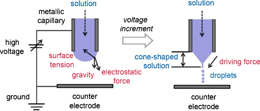
Schematic illustrations of electrospray [1].
Recently, we have reported the preparation of spherical TiO2 nano- and microparticles by the electrospray pyrolysis method [5]. As a precursor, titanium(IV) bis (ammonium lactato) dihydroxide aqueous solutions (TALH aq. 0.2–20 wt%) was used, and we succeeded to prepare spherical anatase TiO2 particles [5]. However, in the previous work, the final powder yield (Ti base) at the electrostatic collector was only ∼6%, because synthesized particles with same charge repelled each others, and most of them deposited on the reactor walls during the pyrolysis [5].
In this study, a double-nozzle electrospray pyrolysis (DNESP) method, where each nozzle has different DC polarity, has been adopted to improve the final TiO2 powder yield instead of using the single-nozzle electrospray pyrolysis (SNESP, or just ESP) method. The DNESP method enables to neutralize the droplets coming from different nozzles (via merging two or more droplets with different charges) [6–11], and to suppress the deposition on the reactor walls. This study is divided into two parts. In the first part (this article), we optimized the experimental conditions for SNESP, and then, for DNESP to achieve the refinement and monodispersion of sprayed droplets. Size and dispersion state of the droplets were evaluated in detail by using a digital microscope. In the second part, high-yield production and characterization of TiO2 powder will be presented in detail [12]. A supplementary figure (Fig. S1) shows the whole feature of our DNESP apparatus [12].
2 Experimental procedure
First of all, by using the single nozzle (SN), optimum conditions of the electrospray (without pyrolysis) as functions of: (1) liquid flow rates, (2) ground electrode position, and (3) applied voltage were determined. Then, using these optimized conditions for SN, double-nozzle electrospray (DNES) conditions (e.g., inter-nozzle distance) were determined. Finally, we discuss the appropriateness of the DNES system. Table 1 summarizes the experimental conditions evaluated in this study.
Experimental conditions evaluated in this study.
| Parameters | Range |
| Liquid flow rate | 20 ∼ 60 mL/h |
| Ground electrode position | −5 ∼ 15 mm |
| Applied voltage | 3 ∼ 6 kV |
| Inter-nozzle distance | 15 ∼ 30 mm |
As a precursor of TiO2, same as our previous paper [5], titanium(IV) bis (ammonium lactato) dihydroxide aqueous solution (TALH aq., diluted from a commercial 50% aqueous solution, Sigma-Aldrich [13,14]) was used (Fig. 2). Stainless steel capillary nozzles, inner diameter: 0.15 mm, outer diameter: 0.30 mm, length: 30 mm (SNA-30G-30L, Musashi Engineering Inc.) were used for the electrospray.
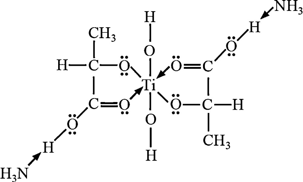
Structure of TALH. TiO6 octahedron exists in this precursor.
In the SN setting, TALH aqueous solution (2.0 wt%) was injected into a capillary nozzle by a syringe pump (Model-100, KD Scientific, 20–60 mL/h), and was electrosprayed by using positive DC voltage (HSX-10R 1.5, Matsusada Precision Inc., 3–6 kV). In the DN setting, TALH aqueous solution (2.0 wt%) and pure H2O were separately injected into capillaries by two syringe pumps, and were electrosprayed by using positive and negative DC voltage, respectively. Coalescence of droplets with positive and negative charges result in the charge neutralization.
Size of the electrosprayed droplets (both for SN and DN settings) was quantitatively characterized by a digital microscope (droplet-fixation method) [5,15]. As shown in Fig. 3, electrosprayed droplets were collected on a petri dish, then sealed in a vapor of α-cyanoacrylate (major component of an instant glue). Due to the polymerization of α-cyanoacrylate vapor with droplets, the shape and size of droplets are fixed.
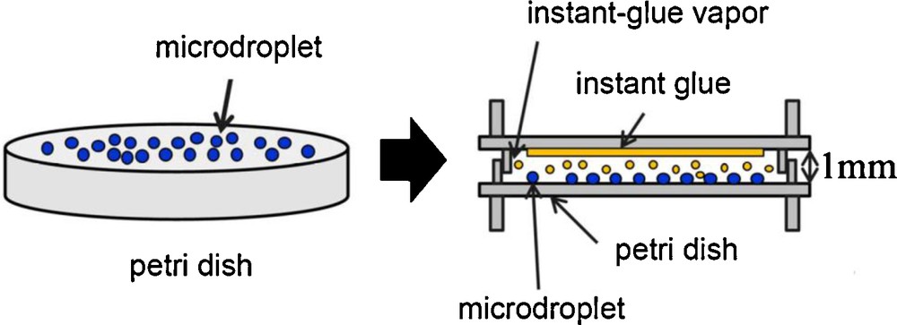
Droplet-fixation method developed by Tohno et al. [5,15].
Detail of the droplet-size measurement system is illustrated in Fig. 4. The carrier gas (purified air) was bubbled through pure water to control the humidity as 92%, in order to avoid the vaporization of droplets. Electrosprayed droplets (either by SN or DN setting) transported by the humidified carrier gas were collected at the petri dish (10 cm from the nozzle edge) for 5 s. After the 5 s collection, the petri dish was sealed in a vapor of α-cyanoacrylate for 15 min. With confirming the polymerization, 200 fixed droplets were observed by using a digital microscope (VHX-100, Keyence. Co) to determine the average diameter of the droplets.
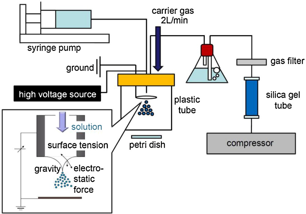
Droplet-size measurement system (for the single-nozzle setting).
3 Results and discussion
3.1 Optimization of liquid flow rates
Firstly, under the SN setting, optimization of the liquid flow rate was carried out. The liquid flow rate of the 2% TALH solution was varied as 20, 30, 40, 50 and 60 mL/h. As for other parameters, applied voltage was fixed to +4 kV, and the ground position (later in detail) was fixed to 0 mm (same height as the nozzle tip). Fig. 5 shows digital microscope images and size distributions of the droplets at each liquid flow rate, and Fig. 6 summarizes the mean droplet size and the geometric standard deviation (inserted values) as a function of the liquid flow rate. According to Fig. 6, with increasing the liquid flow rate, droplet size decreased with the minimum at 50 mL/h. However, the geometric standard deviation at 50 mL/h became relatively large value of 1.39. On the other hand, the geometric standard deviation became minimum (1.20) at 30 mL/h.
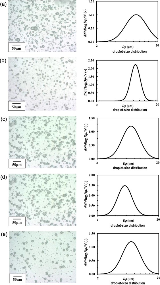
Digital microscope images and size distribution of electrosprayed droplets at different liquid flow rates. The applied voltage was fixed to +4 kV, and the ground position was fixed to 0 mm (dmean: mean droplet size, GSD: geometrical standard deviation): (a) 20 mL/h (dmean 8.81 μm, GSD 1.49); (b) 30 mL/h (dmean 8.62 μm, GSD 1.20); (c) 40 mL/h (dmean 7.08 μm, GSD 1.39); (d) 50 mL/h (dmean 5.64 μm, GSD 1.31); (e) 60 mL/h (dmean 7.12 μm, GSD 1.39).
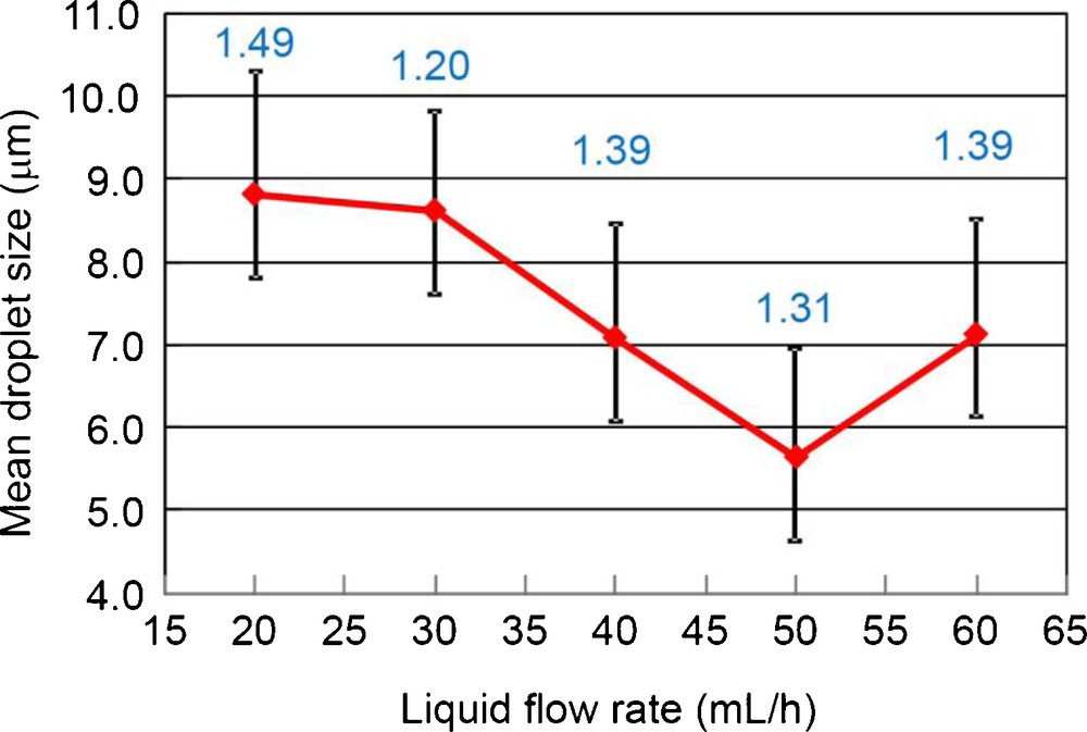
Mean droplet size and geometric standard deviation (inserted values) as a function of the liquid flow rate. The applied voltage was fixed to +4 kV, and the ground position was fixed to 0 mm.
The droplet number density was maximum at 20 mL/h, and minimum at 50 mL/h, which is probably related to the spray angle. With increasing liquid flow rate from 20 to 50 mL/h, electrospray was spread to wider angle, resulting in the droplets being piled up outside the petri dish surface. At 60 mL/h, cone-jet was spread into 2 jets, and the spray became unstable. That is why there was two groups of droplets (large and small) in Fig. 5(e). Although 30 mL/h was the best for the monodispersion, from the view point of the size refinement (and also the production speed), we selected 50 mL/h as provisionally optimum liquid flow rate in this study because the mean droplet size was minimum.
3.2 Optimization of ground electrode position
At the flow rate of 50 mL/h, deviation of droplet size was not minimum. Hence, we tried to optimize the ground electrode position (with 5 mm step) to stabilize the single-nozzle electrospray, and tried to achieve the monodispersion. Fig. 7 shows an illustration of the ground electrode position; the reference point (= 0 mm) was set to the nozzle tip. Upper and lower sides were called as minus and plus directions, respectively. The ground position was varied as −5 mm, 0 mm, 5 mm, 10 mm and 15 mm. As for other parameters, liquid flow rate of the 2% TALH solution was fixed to 50 mL/h, and applied voltage was fixed to +4 kV.
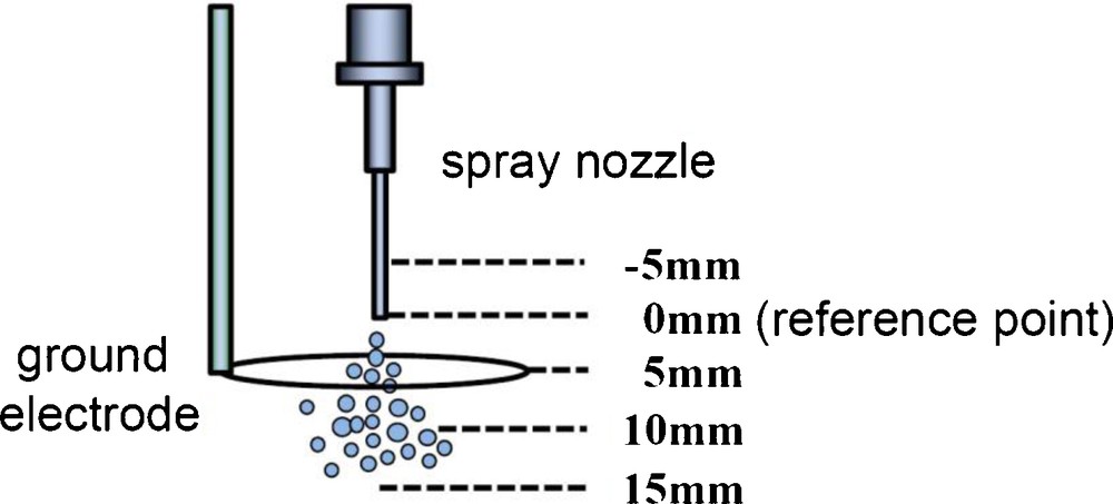
Ground electrode position.
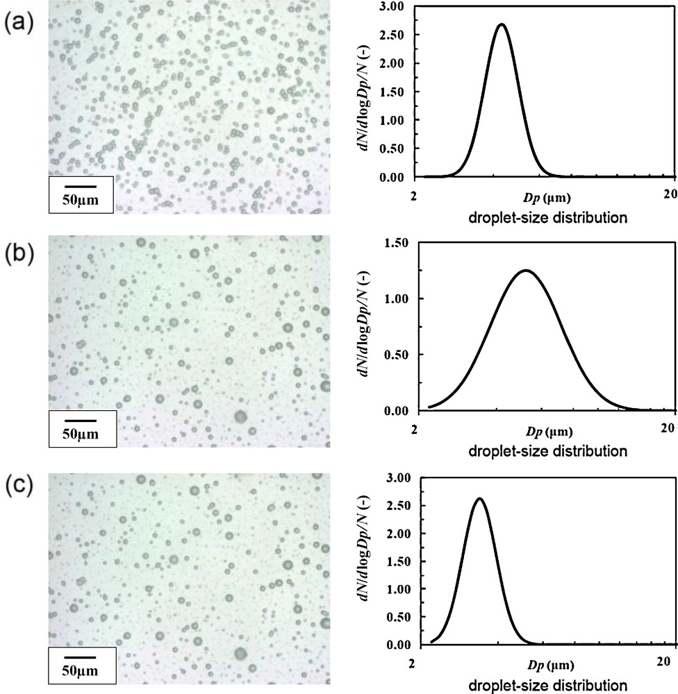
Fig. 8 shows digital microscope images and size distributions of electrosprayed droplets at different ground electrode positions, and Fig. 9 summarizes the mean droplet size and geometric standard deviation (inserted values) as a function of the ground electrode position. As can be seen in Fig. 9, except for the 0 mm, droplet size became small as around 5 μm. As the ground electrode positions varied from −5 mm to 10 mm, electrospray became stabilized, and well-controlled cone-jet was formed. In particular, at the 10 mm, the electrospray was most stabilized, and thus, geometric standard deviation (GSD) of the droplet size was 1.16 (i.e., almost monodispersion). The number density of the droplets was also large at this condition (Fig. 8(d)).
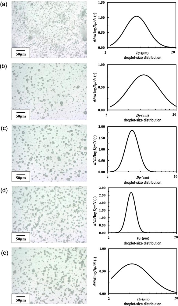
Digital microscope images and size distribution of electrosprayed droplets at different ground electrode positions. The liquid flow rate was fixed to 50 mL/h and the applied voltage was fixed to +4 kV (dmean: mean droplet size, GSD: geometrical standard deviation). (a) −5 mm (dmean 5.34 μm, GSD 1.47); (b) 0 mm (dmean 6.76 μm, GSD 1.67); (c) 5 mm (dmean 4.54 μm, GSD 1.24); (d) 10 mm (dmean 5.00 μm, GSD 1.16); (e) 15 mm (dmean 4.40 μm, GSD 1.83).
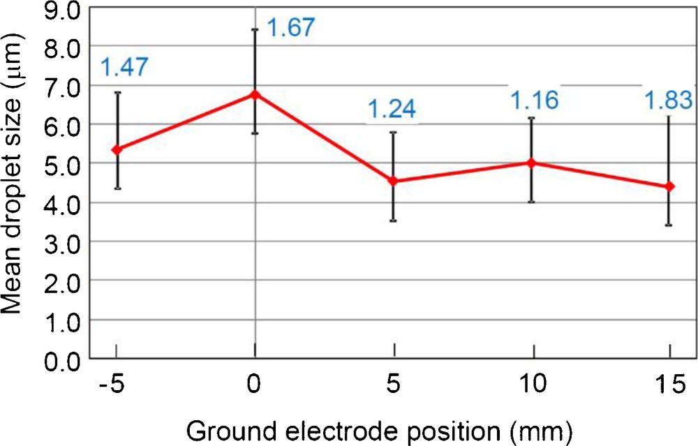
Mean droplet size and geometric standard deviation (inserted values) as a function of the ground electrode position. The liquid flow rate was fixed to 50 mL/h and the applied voltage was fixed to +4 kV.
When the ground electrode position was at 15 mm, however, the electrospray was destabilized, resulting the GSD of 1.83. This phenomenon can be explained by the inhomogenization of the electrostatic-induction field, due to the long distance of spray nozzle and ground electrode. From the view point of the size refinement and monodispersion, we selected 10 mm as the optimum ground electrode position.
3.3 Optimization of applied voltage
In order to obtain much finer and monodispersed droplets, optimization of the applied voltage was carried out. Applied voltage was varied as +3 kV, +4 kV, +5 kV and +6 kV. The liquid flow rate of the 2% TALH solution was fixed to 50 mL/h, and the ground position was fixed to 10 mm.
Fig. 10 shows digital microscope images and size distributions of electrosprayed droplets at different applied voltages, and Fig. 11 summarizes the mean droplet size and geometric standard deviation (inserted values) as a function of the applied voltage. At +3 kV, electrospray was not observed. Non-sprayed drops fell down from the nozzle tip (viz., drip-mode). At +4 kV, normal electrospray with cone-jet was observed. The electrosprayed droplets were monodispersed with GSD of 1.16 (as shown in the above section). At +5 kV, dispersion state became worse than that at +4 kV. The GSD at +5 kV was 1.38. This is due to the change of electrospray mode, i.e., from cone-jet mode (+4 kV) into multi-jet mode (+5 kV). Each jet formed droplets with different size, which resulted in the inhomogeneous distribution. At +6 kV, the electrospray mode was further changed into two jets. From these main jet streams, the majority of droplets was directed to the plastic tube wall (Fig. 4). From a minor jet between these two jets formed small droplets with GSD of 1.16 (Fig. 10(c)), they are “by-product.” So, we selected +4 kV as the optimum applied voltage. Optimized SN electrospray is shown in Fig. 12.
Digital microscope images and size distribution of electrosprayed droplets at different applied voltage. The liquid flow rate was fixed to 50 mL/h and the ground electrode position was fixed to 10 mm (dmean: mean droplet size, GSD: geometrical standard deviation). (a) +4 kV (dmean 5.00 μm, GSD 1.16), (b) +5 kV (dmean 5.22 μm, GSD 1.38), (c) +6 kV (dmean 3.40 μm, GSD 1.16).
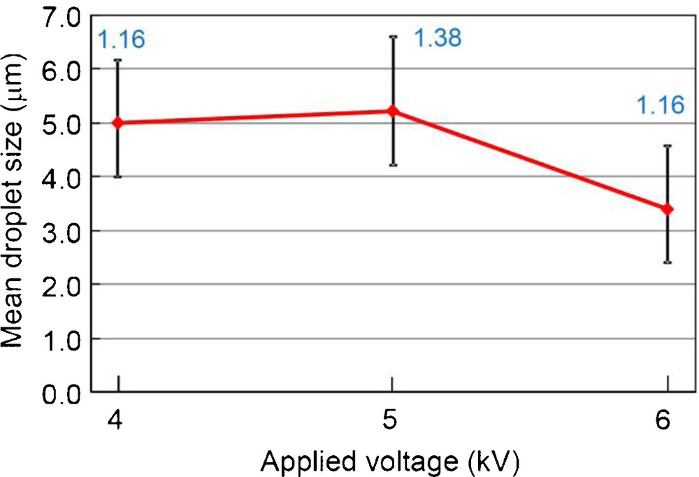
Mean droplet size and geometric standard deviation (inserted values) as a function of the applied voltage. The liquid flow rate was fixed to 50 mL/h and the ground electrode position was fixed to 10 mm.

Optimized single-nozzle electrospray in this study: the liquid flow rate of 50 mL/h, the ground electrode position of 10 mm, and the applied voltage of +4 kV.
3.4 Optimization of inter-nozzle distance for DN setting
From this section, optimization for double-nozzle electrospray (DNES) is described. As for the DN setting, inter-nozzle distance is an important parameter, because it affects the electric field and also the discharge. We examined DNES with different inter-nozzle distances, namely, 15 mm, 20 mm, 25 mm and 30 mm, by using a tentative setting without plastic tubes surrounding the nozzles and ground electrode (Fig. S3). For DNES, the conditions were as follows: liquid flow rate of TALH solution was 50 mL/h (applied voltage of +4 kV), liquid flow rate of pure H2O was also 50 mL/h (applied voltage of −4 kV), and ground electrode position was 10 mm.
When the inter-nozzle distance was 15 mm, discharge occurred. As for the 20–30 mm position, there was no discharge, and electrosprays from two nozzles were observed. However, at 20 and 25 mm, due to the interaction of two electrosprays, sprays became inclined. As for 30 mm, from two electrosprays, two cone-jets were emitted in parallel. Hence, inter-nozzle distance for DNES was set as 30 mm.
3.5 Double-nozzle electrospray in a real apparatus
After the optimization of the three parameters for SN (Sections 3.1–3.3), and optimization of the inter-nozzle distance for DN (Section 3.4), DNES process was then optimized by using a setting similarly to Fig. 4 (but with double nozzle). The initial parameters were same as Section 3.4, that is, liquid flow rate of TALH solution was 50 mL/h (applied voltage of +4 kV), liquid flow rate of pure H2O was also 50 mL/h (applied voltage of −4 kV), ground electrode position was 10 mm, and inter-nozzle distance of 30 mm. In this trial, since both TALH solution and pure H2O flowed both 50 mL/h (i.e. in total 100 mL/h), droplets tended to attach to the reactor wall and nozzles, which induced the discharge.
When both flow rates were changed into 30 mL/h (minimum GSD in Section 3.1), i.e. in total 60 mL/h, there was no discharge, and all droplets were directed to the inside of reactor tube. Fig. 13 shows the digital microscope image and the size distribution of electrosprayed droplets for optimized double-nozzle electrospray in this study, where mean droplet size was 7.58 μm and GSD was 1.37. Due to the coalescence of the droplets with different charges, the size and GSD of DNES became larger than those of SNES. Table 2 summarizes the optimum conditions for the DNES in this study.
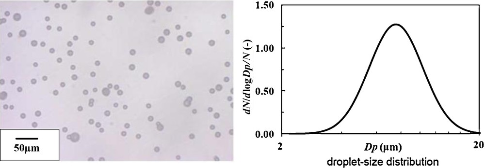
Digital microscope image and size distribution of electrosprayed droplets for optimized double-nozzle electrospray in this study, dmean: 7.58 μm, GSD: 1.37.
Optimum conditions for double-nozzle electrospray in this study.
| Parameters | Range |
| Liquid flow rate (TALH solution) | 30 mL/h |
| Liquid flow rate (pure H2O) | 30 mL/h |
| Ground electrode position | 10 mm |
| Applied voltage (TALH solution) | +4 kV |
| Applied voltage (pure H2O) | −4 kV |
| Inter-nozzle distance | 30 mm |
4 Conclusions
In this study, we have examined electrospray parameters for both single-nozzle and double-nozzle settings. By using the droplet-fixation method, quantitative analyses of the size and dispersion state were conducted. As for the single-nozzle electrospray, fine monodispersed droplets were formed (mean droplet size: 5 μm, geometrical standard deviation (GSD): 1.16). As for the double-nozzle electrospray, the size and GSD were slightly larger as 7.58 μm and 1.37, due to the coalescence of the droplet with different charges. However, thanks to the neutralization of droplets by double-nozzle electrospray, final powder yield after pyrolysis was much improved from 6% (in previous work) into 55.4% (reported in detail in the forthcoming report [12]).