

1 Introduction
The increasing concentration of greenhouse gases in the atmosphere contributes to global warming and climate change. CO2 is the main anthropogenic greenhouse gas and its concentration in the atmosphere has increased from a preindustrial value of about 280 ppm to reach 401 ppm (monthly averages) in April 2014 [1]. It is generally accepted that CO2 emissions should be significantly reduced, as a preventive action and in order to stabilize its concentration in the atmosphere, to limit its environmental impact. In 2010, 41% of the worldwide anthropogenic CO2 emissions came from fossil fuel (coal, oil or natural gas) combustion to produce energy [2]. Since transition to renewable energies is a slow process and fossil fuel will still be the dominant energy source in the next decades, CO2 capture and sequestration (CCS) has been proposed as an alternative to reduce CO2 emissions from fossil fuel power plants. CCS is a process consisting in the separation of CO2 from industrial and energy-related flue gases, transport to a storage location and long-term isolation from the atmosphere [3]. The current CO2 capture systems consist in pre-combustion, oxy-fuel combustion and post-combustion systems. These techniques have a main disadvantage; they exhibit a high-energy penalty, which decreases the overall efficiency of the power plant by around 15–20% [4]. Many efforts are undertaken to develop new inexpensive CCS technologies [5]. The chemical looping combustion (CLC) has proven to be an efficient alternative to reduce the cost of CO2 capture. It is an innovative technology, which allows the production of energy with a selective capture of CO2 and low energy penalty [6,7]. In this cyclic process, the oxygen needed for the combustion is provided by an oxygen carrier that is alternatively reduced by the fuel according to reaction (1) and oxidized by air (reaction (2)).
| (2n + m) MyOx + CnH2m → (2n + m) MyOx–1 + m H2O + n CO2 x ≥ 1 | (1) |
| (2n + m) MyOx–1 + (n + 0.5 m) O2 → (2n + m) MyOx | (2) |
The main advantage of this technology compared to conventional combustion is that the combustion is carried out without air. Thus, exhaust gases from the fuel combustion reaction are mainly composed of CO2, H2O; after water condensation, pure CO2 can be obtained. The gas mixture produced during re-oxidation of the oxygen carrier contains nitrogen and some unreacted oxygen. So, it can be directly released to the atmosphere. Moreover, this process also ensures that no thermal NOx are produced in the flue gas, due to the absence of extremely high temperatures [8]. Reaction (2) is extremely exothermic, while reaction (1) can be endothermic or exothermic, depending on the metal oxide and the fuel used. The heat balance during the CLC process is the same as the one released during conventional combustion.
This cyclic process can be carried out in two ways: by moving the oxygen carrier between two static gas flows or by maintaining the oxygen carrier static while switching the gas streams. The first option is carried out in two interconnected fluidised bed reactors, whereby the oxygen carrier is continuously circulated between a fuel reactor, where it is reduced and an air reactor where it is regenerated [9,10] (see Fig. 1a). This option has been widely studied since the 1980s and several units for gaseous fuels can be found in the literature (from 10 kkWth. units [11–13] to 1 MW [14]). The second option (see Fig. 1b) was first proposed by Noorman et al. [15,16] and consists in using dynamically operated packed-bed reactors where the particles remain stationary and a valve system switches the gas flow periodically. In this case, the difficult gas-solid separation is avoided.
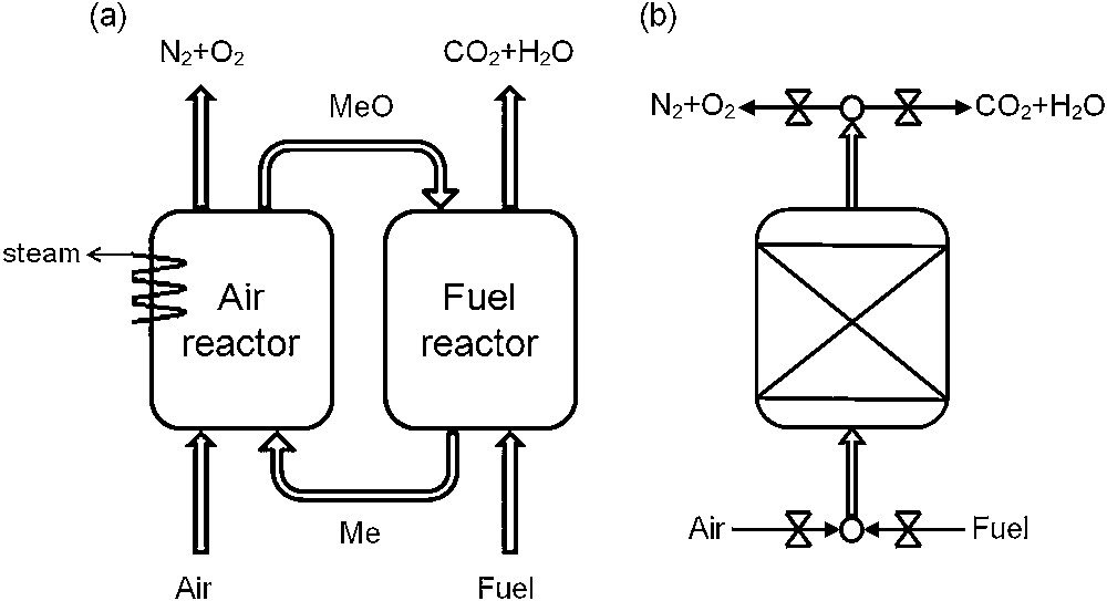
Possible CLC configurations: (a) interconnected fluidized beds, (b) packed-bed.
The success of a large-scale CLC application depends on finding suitable oxygen carriers that exhibit significant oxygen transport capacity, fast reduction/oxidation rates and chemical/physical stability [17]. Several metal oxides such as NiO [18], CuO [19,20], Mn3O4 [21,22] and Fe2O3 [23,24] have been proposed as potential candidates for CLC. These metal oxides cannot be used alone, as their rate of oxidation is extremely slow (even at high temperatures), because oxidation takes place only at the external surface layer due to shrinkage of particles during reduction reaction [8,25]. This is the reason why they are generally mixed with a porous binder (e.g., Al2O3, NiAl2O4, MgO, MgAl2O4, SiO2, TiO2, stabilized ZrO2…) that increases mechanical strength and provides a higher surface for reaction [26]. The binder increases porosity and consequently, improves the conversion and oxidation rates. It is supposed to be an inert material, stable also at high operating temperatures. However, it has been observed by Gayán et al. [27] that this binder can sometimes interact with the metal oxide or react with the fuel.
NiO/NiAl2O4 material has been widely studied and it is one of the most performing oxygen carriers, due to its high reactivity, also at high temperatures (900–1100 °C) [28,29]. First, some authors studied the possibility of supporting NiO on Al2O3. The problem of using this binder is that it may react to form NiAl2O4 at high temperatures (> 800 °C) [30–32]. The formation of this surface spinel phase (NiAl2O4) decreases the reactivity of the oxygen carrier [33]. To avoid this problem, it was suggested by Jin et al. [34] to use directly NiAl2O4 as a binder. This new material (NiO/NiAl2O4) showed an excellent reactivity with many fuels (CH4, CO and H2) and good stability in the course of the cyclic reaction. Afterwards, many authors have studied the reactivity and kinetics of this oxygen carrier prepared by different methods (freeze granulation [35], spray drying [29], impregnation [36]…) at different scales (thermogravimetry [37], laboratory scale [38,39] and pilot plant [40]), and in all cases, good performances of this oxygen carrier were observed.
It has been noted by Adánez et al. [41] and by Dueso et al. [42,43] that the oxygen available in the NiAl2O4 binder seems also to react with the fuel contributing as an additional reaction to the one of nickel oxide. Adánez et al. studied methane combustion in a 500-Wth. CLC system with 18 wt % NiO impregnated on α-alumina during 100 h. They observed that two different phases were present on the oxygen carrier, NiO and NiAl2O4, and that both of them were active to transfer oxygen to the fuel. Therefore, NiAl2O4 cannot be considered as an inert material. Dueso et al. performed oxidation–reduction cycles through thermogravimetric analyses (TGA) with the same oxygen carrier (initially NiO/α-Al2O3), and they also observed the formation of nickel aluminate and that the reduction rate of NiO (determined at the beginning of the reduction step) was faster than the one of NiAl2O4. So, NiAl2O4 formation decreases the performances of the oxygen carrier. However, these authors have not tested the reactivity of the binder (NiAl2O4) alone.
Due to its strong resistance to acids and its high melting point, NiAl2O4 has been widely used as a support in catalysis [44]. Cesteros et al. [45] have studied how the preparation conditions of NiAl2O4 and the calcination temperature could affect its final structure and its reducibility. They observed that the increase in calcination temperature results in a decrease in the specific surface area (due to the formation of large particles), leading to difficulties in the reduction process and higher initial reduction temperature.
In the case of CLC, it was observed that NiAl2O4 cannot be considered as an inert material, and that both phases (NiO and NiAl2O4) react at the same time with the fuel. The objective of this work is to study the reactivity of the binder (NiAl2O4) and to estimate its contribution to the total reactivity of the oxygen carrier NiO/NiAl2O4. For this, oxidation–reduction cycles were performed with the binder alone. These tests have been carried out in a fixed bed reactor, with CO as fuel, at different operating temperatures. A fixed bed reactor device was chosen to study the NiAl2O4 reactivity at a laboratory scale, because in this configuration, the gas flow goes through the bed and the mass transfer is mainly governed by forced convection, which removes diffusion limitations (problem observed in TGA). In addition, the results obtained in a fixed bed can be extrapolated to a CLC packed-bed configuration, which is an alternative to interconnected fluidised beds in large-scale applications. CO was chosen as fuel because it is expected to extend the concept of CLC to solid fuels, particularly to coal. An additional gasification step is needed when using coal as fuel, which is followed by an oxidation of the product (synthesis gas, which is a mixture of CO and H2). Therefore, it is important to study the reactions related to CO. The major aim of this work is to estimate the NiAl2O4 reduction capacity during oxidation/reduction cycles. For this purpose, an experimental design (full factorial central composite design) was used to study the effects of reduction operating parameters (temperature and fuel concentration) on the reactivity of NiAl2O4. This methodology provides the maximum information on the operating parameter influences, with a minimum number of experimental tests [46]. In addition, X-ray diffraction (XRD) analyses have been performed to study the evolution of the NiAl2O4 spinel phase upon redox cycling.
2 Experimental part
2.1 Material
NiO/NiAl2O4 is the oxygen carrier used in TGA studies. It was supplied by IFP Energies Nouvelles (IFPEN) and its composition is: 60 wt. % NiO and 40 wt. % NiAl2O4. The particle size is in the range of 100–300 μm. The particles were prepared by granulation (in a Guedu granulator) and then, they were calcined at 1200 °C for 2 h.
The binder, studied in a fixed bed reactor, is a nickel aluminate powder (NiAl2O4) provided by IFPEN (Solaize, France). It was synthesized (by Cabot Society) by spray pyrolysis of nickel nitrate Ni(NO3)2 and γ-alumina (spectral 100). The obtained powder was then calcined in air at 800 °C and 1000 °C during 24 h for each temperature, and shaped by pressure pelletization and further calcination at 600 °C. The pellets were crushed to retain particle sizes between 125 and 300 μm.
2.2 Experimental set up
This research consists in performing reduction/oxidation cycles of the binder (NiAl2O4) in a fixed bed reactor used in previous studies [47] and described in Fig. 2. A total of 0.20 g of NiAl2O4 is deposited on a fused silica frit placed in a vertical quartz reactor (inner diameter: 6 mm). This reactor with a small diameter allows working with relatively small amounts of NiAl2O4, while keeping a significant bed height of 4–5 mm and, moreover, to have dynamic conditions that are favourable to a good heat and mass transfer. Indeed, studies of Residence Time Distribution performed with this reactor with a bed height of 5 mm show that the reactor behaves as a plug flow reactor with axial diffusion. The fixed bed is heated by a tubular Pekly/Herrmann–Moritz furnace and the temperature of the material is measured by two K-type thermocouples placed on both sides of the bed. Oxidation and reduction cycles are conducted at a constant gas flow rate of 50 NL·h−1, fixed by BROOKS 5850 mass flow controllers. One security valve (Fig. 2) was installed before the reactor to avoid fuel and oxidizing gas (air) mixing. The reduction step is performed under CO (0.1 to 1 vol.%) under nitrogen at different temperatures, ranging from 700 to 900 °C. The regeneration step (oxidation cycle) is conducted in the air, from room temperature to reduction temperature.
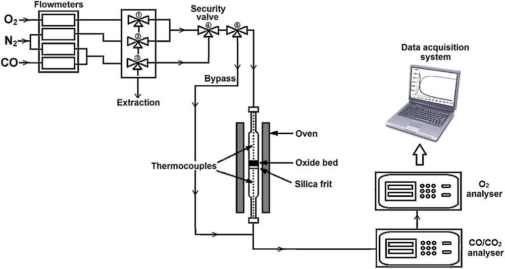
Experimental device for oxidation/reduction cycles of NiAl2O4 in a fixed bed reactor.
CO, CO2 and O2 concentrations at the reactor outlet are continuously measured by an infrared analyser NG2000 (for CO and CO2, range 0–1 vol.%) and a paramagnetic analyser Rosemount X-stream (for O2, two ranges 0–20 vol.% and 0–100 vol.%). Data acquisition (time, temperature and concentrations) is carried out using a module NUDAM, and all data are recorded in real time throughout the tests.
2.3 Procedure used in fixed bed reactor
The procedure used in this study consists of an oxidation step (regeneration step) of the binder, where the sample is heated under oxidizing atmosphere (air) from room to reduction temperature (heating rate of 10 °C·min−1), followed by an inerting step of 10 min to remove all oxygen traces in the reactor. Then a mixture of CO/N2 is injected to reduce the material (reduction step). This step is considered finished when the CO concentration in the exhaust gas is the same as that in the injected one. Finally, the sample is cooled down to ambient temperature under nitrogen. Then a new oxidation–reduction cycle can start.
2.4 Thermogravimetric measurements
Thermogravimetric analyses (TGA) were performed on the oxygen carrier NiO/NiAl2O4 and on the binder alone, with a SETARAM SETSYS thermobalance operated with a vertical gas flow of 15 NL·h−1. Oxidation–reduction cycles are performed on 10 mg of NiO/NiAl2O4, with an inerting step between reaction periods (as in fixed bed configuration). The reduction step is carried out under 4000 ppm CO in N2 at two different temperatures (750 °C and 900 °C), and oxidation is carried out in the air. In TGA measurements, the regeneration of the material (oxidation step) is realized at the same temperature as that of the reduction cycle.
2.5 Sample characterization
XRD (X-ray diffraction) measurements are performed in transmission mode using Cu Kα1 radiation (λ = 1.5418 Ǻ), on samples which are packed into glass capillaries in a Stadi-P (STOE) diffractometer. Measurements were achieved for values of the 2θ angle in the 10 − 90° range, step 0.1°, and time/step = 55 s.
3 Results
3.1 NiO/NiAl2O4 oxidation–reduction cycles in TGA
To start this study, an experimental investigation is carried out with the oxygen carrier NiO/NiAl2O4 in TGA. Two series of 24 cycles are performed at two different reduction/oxidation temperatures (750 and 900 °C). The mass variation during reduction cycles is measured in real time and corresponds to the reduction of the nickel oxide NiO associated with the binder NiAl2O4, which is supposed to be inert. Indeed, only NiO is supposed to oxidize CO in CO2. The maximal number of moles of NiO that is reduced by CO represents the total oxygen exchange capacity of the oxygen carrier and is noted TC (Total reduction Capacity). TC is calculated from TG curves. Fig. 3 shows the evolution of TC balanced by the total number of moles of oxygen atoms available in NiO, for two studied temperatures during successive reduction cycles.
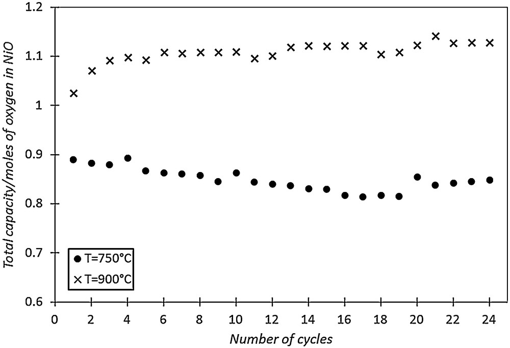
NiO/NiAl2O4 total reduction capacity (TC) during 24 oxidation–reduction cycles for two different operating temperatures.
Fig. 3 shows that TC is relatively stable at 750 °C during successive reduction cycles and is lower than the one observed at 900 °C. At high temperature (900 °C), the total number of moles of oxygen that has reacted with CO is higher than the theoretically number of available oxygen atoms, based on the amount of NiO initially present in the oxygen carrier. This result can be explained by the probable contribution of the binder NiAl2O4 to the oxidation of carbon monoxide at 900 °C. Therefore, TGA indicates that the NiAl2O4 binder is also active to transfer oxygen, and contributes to increase the total reduction capacity of NiO/NiAl2O4 at 900 °C.
Thus, it is important to study the reactivity of the binder with fuel and its contribution to the oxygen carrier performances.
3.2 Experimental results of oxidation–reduction cycles in fixed bed reactor on the binder NiAl2O4
In order to analyse the reactivity of the NiAl2O4 binder in different conditions of temperature and fuel concentrations, a parametric study of the reduction step was conducted using a Design Of Experiments methodology (DOE). This methodology is used in many fields [48], and allows one to obtain the maximum information about the influence of the operating parameters on the process, with a minimum of experimental tests. In this case, the influence of two reduction parameters (temperature and concentration of injected CO) on the total reduction capacity of the NiAl2O4 binder is studied. The studied range is 700–900 °C and 0.1–1 vol.% for temperature (T) and injected CO concentration ([CO]), respectively.
Parameters of each test (T and [CO]) are chosen to optimise the number and the relevance of the experimental tests. To compare the effects and the influence of these parameters between them, they are normalized in the studied range. The design (rotatable central composite design) consists in three distinct sets of experimental runs:
- • a set of centered points, experimental runs whose values of each factor are the medians of the studied range (noted 0, see Fig. 4, round point),
- • an orthogonal factorial design with two levels (+1, –1, square points in Fig. 4),
- • and a set of axial points, experimental runs identical to the centre points except for one factor, which will take on values typically outside the studied range (+α, –α, cross points in Fig. 4).
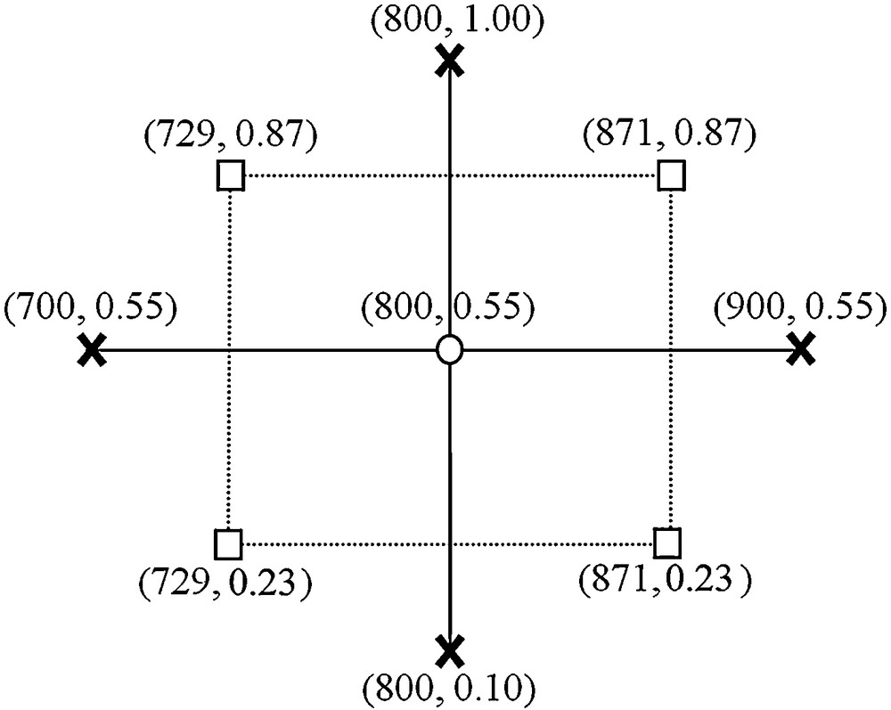
Design of experiments to study NiAl2O4 reactivity.
The value of α is estimated from the following relation , in this case .
Therefore, nine points of study are defined by this methodology (for two studied parameters). All the tests are systematically repeated twice and performed with the same NiAl2O4 sample, from the lowest temperature to the highest, to limit possible performance modifications due to high temperatures. Total reduction capacity (TC) of the binder in the fixed bed configuration, which corresponds to the maximal number of moles of CO2 produced per gram of NiAl2O4, is calculated for each test from the integration of the CO2 curve. The intersection time corresponds to the time at which CO and CO2 concentrations are equal. Results obtained for each experimental condition are shown in Table 1. These results confirm that the NiAl2O4 binder reacts with the injected CO to produce CO2. Indeed, the amount of CO2 produced during the reduction step is not negligible and increases (2.2 times more) during cycles (from 1 to 18) and with temperature. The presence of traces of NiO in the fresh binder NiAl2O4 observed by XRD characterizations, cannot explain this significant CO oxidation capacity. This increase of reduction capacity certainly indicates structural changes in the binder. A similar behaviour of the binder has been also observed during TGA studies. Indeed, a significant activity of NiAl2O4 has been noted during reduction cycles performed in a thermobalance under CO at 900 °C.
Experimental values of TC and intersection time for different reduction temperatures and CO concentrations.
| Tests | Temperature of reduction step (°C) | Injected CO concentration (vol.%) | CO2 produced (mol·g−1) | Intersection time (s) |
| 1–2 | 700 | 0.55 | 9.85·10−4 | 55 |
| 3–4 | 729 | 0.23 | 1.18·10−3 | 92 |
| 5–6 | 729 | 0.87 | 1.17·10−3 | 42 |
| 7–8 | 800 | 0.10 | 1.78·10−3 | 430 |
| 9–10 | 800 | 0.55 | 1.54·10−3 | 76 |
| 11–12 | 800 | 1.00 | 1.71·10−3 | 53 |
| 13–14 | 871 | 0.23 | 2.01·10−3 | 168 |
| 15–16 | 871 | 0.87 | 1.97·10−3 | 74 |
| 17–18 | 900 | 0.55 | 2.20·10−3 | 126 |
The total amount of framework oxygen in the binder is approximately equal to 2.26·10−2 mol·g−1. As the alumina network is stable and inert at high temperature, it is considered that only a quarter of the oxygen in the binder may react with CO and probably generate metallic nickel and alumina. Taking these considerations into account, the comparison of the amount of CO2 produced with regard to the amount of oxygen available in the nickel aluminate shows that a high proportion of oxygen may react with CO to form CO2. This proportion of reacting oxygen is equal to 17% during the first cycle and reaches 38% for tests 17 and 18.
Fig. 5 represents the CO and CO2 concentration curves versus time, during the reduction step at three different temperatures (corresponding respectively to tests 1, 9 and 17). For the three tests, the injected CO concentration is equal to 5500 ppm and the temperatures are respectively 700 °C, 800 °C and 900 °C.
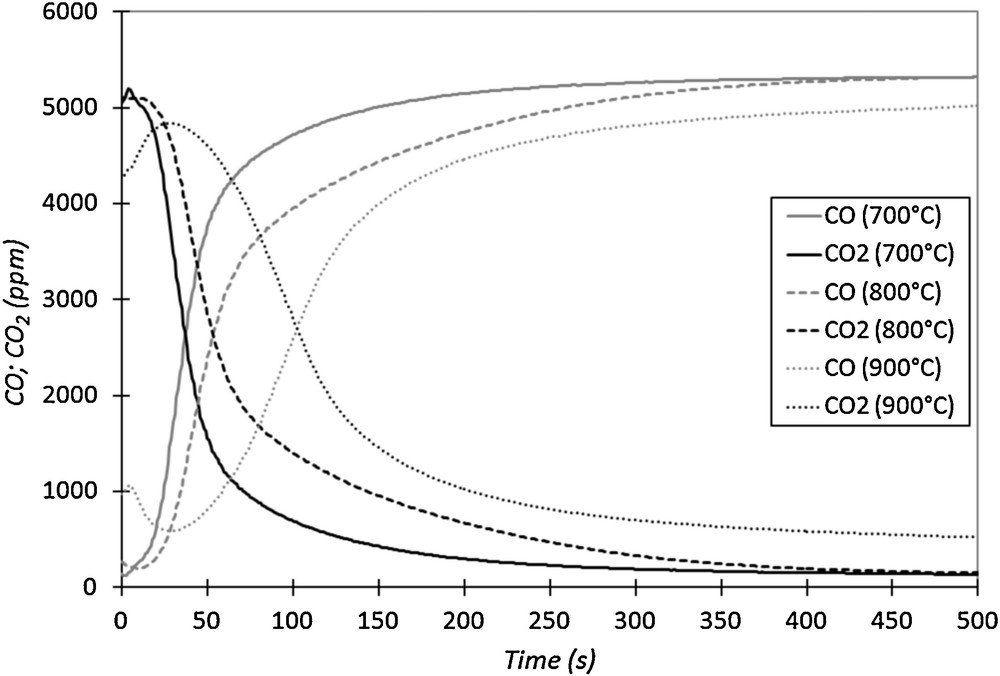
CO and CO2 outlet concentrations versus time for three cycles at different temperatures (injected CO concentration of 0.55 vol.% in N2, 50 NL·h−1).
Fig. 5 shows that the shape of the CO and CO2 curves for these three cycles is different, depending on the reduction cycle temperature. The intersection time of the curves increases with temperature (see also Table 1). In addition, after 500 s of reduction at 900 °C, a significant production of CO2 is still observed, which indicates that the binder is still reacting with CO, unlike at 700 °C and 800 °C. At high temperature (900 °C), the binder is not stable in the presence of CO.
Two additional tests conducted in the same conditions as in tests 1 and 2 were performed (tests 19 and 20) to verify the possible variation of the binder's performances in CO oxidation due to high temperature treatment. Fig. 6 represents the outlet CO and CO2 concentrations versus time, during reduction cycles 1 and 19. The observed changes between the curves of cycles 1 and 19 indicate that the binder performances have been deeply modified by the previous reduction/oxidation cycles set at high temperatures (Fig. 6). Indeed, the intersection time has increased. It is equal to 55 s for cycle 1 and reaches 150 s for cycle 19. The integration of the two series of CO2 curves indicates that the total reduction capacity during cycle 19 (2.55·10−3 mol·g−1) is 2.6 times larger than that of cycle 1 (9.85·10−4 mol·g−1). The latter result indicates that the performance of the binder in fuel oxidation has evolved during reduction/oxidation cycles at high temperature and highly increased. This modification of the material performance may demonstrate some structural changes in the binder.
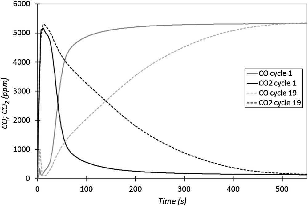
CO and CO2 outlet concentrations versus time for cycles 1 and 19 performed in the same reduction conditions (700 °C, 5500 ppm of CO in N2, 50 NL·h−1).
3.3 Characterization of the samples
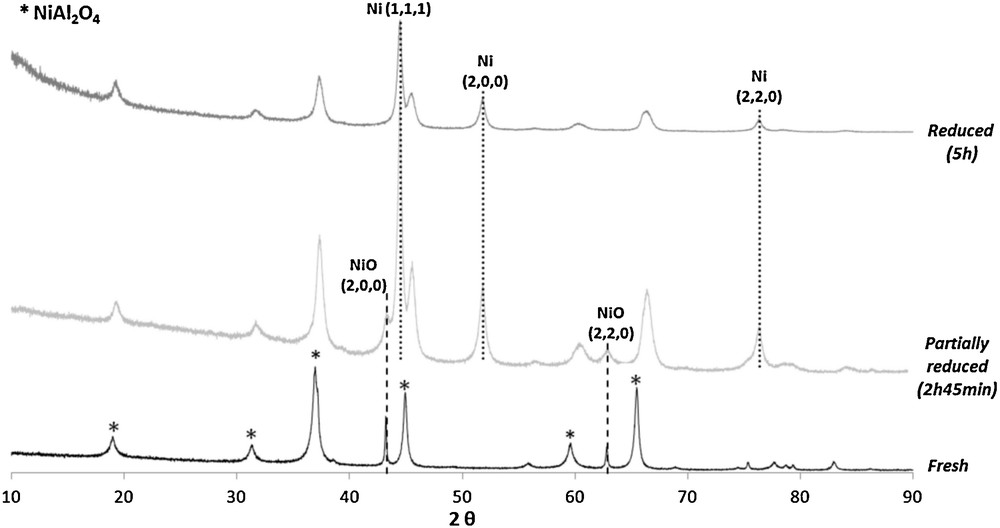
To understand the modifications undergone by the binder during oxidation–reduction cycles and explain its reactivity, XRD experiments were carried out. First of all, the fresh binder was analysed. The XRD pattern of the fresh material (Fig. 7) shows only characteristic peaks of nickel aluminate and nickel oxide phases. The presence of NiO traces in the fresh binder is probably due to the preparation method. Fig. 7 also shows XRD patterns of the binder after reduction cycles of different durations. These two reduction steps were conducted at 750 °C with different concentrations of injected CO (2100 ppm and 5500 ppm in N2 at 50 NL·h−1). In these two reduced samples, peaks of metallic nickel are present. The presence of nickel oxide is also observed for the sample that has been reduced during 2h45 with the lowest concentration of injected CO (2100 ppm). For the sample that has been reduced longer (5 h) and with the higher concentration of inlet CO (5500 ppm), nickel oxide is not detected by XRD. Only metallic nickel is present in this highly reduced material.
XRD pattern of the fresh, partially reduced and highly reduced material.
The disappearance of nickel oxide during the reduction cycle proves that NiO phase reacts with the fuel (CO). The presence of peaks of NiO after 2h45 of treatment under CO indicates that, at this time, a part of this oxide has not yet reacted with the injected fuel. The CO and CO2-versus-time curves obtained during the two reduction steps are presented in Fig. 8. When XRD measurements were carried out on the partially reduced binder, CO and CO2 emissions were stable and low for CO2, indicating that almost all of the injected CO was not oxidized on the binder at this time of the reduction step (2h45), despite the presence of NiO in the binder (Fig. 7). This result indicates that these nickel oxide particles are not reactive (or almost not) with the fuel, because their accessibility is probably limited at 750 °C. It could indicate the presence of diffusion limitations inside material porosity. On the other side, when the reduction step is longer and coupled with a higher concentration of inlet CO in the gas phase, the conversion rate of NiO to Ni metal is improved as in the highly reduced material (Fig. 7). In this case, the duration of the reduction step is long enough to reduce all the NiO particles in Ni metal (after 5 h of treatment under CO).
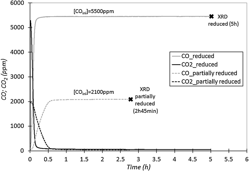
CO and CO2 outlet concentrations versus time, for two reduction cycles with different durations and injected CO concentrations (750 °C, 50 NL·h−1).
Fig. 9a shows the XRD patterns of the fresh binder and after ten cycles of oxidation–reduction. The two studied materials are in oxidized state. Fig. 9b and c are two enlargements of different parts of the patterns. The first observation is that there is no peak of metallic nickel in the two samples. The patterns present only characteristic peaks of nickel oxide and nickel aluminate phases. All the reactive species that are supposed to be reactive with CO should be in the form of nickel oxide after the regeneration step. The second observation (enlargements in Fig. 9b and c) indicates that there is a shift of all the peaks relative to nickel aluminate towards wide-angle diffraction, whereas the position of nickel oxide peaks remains unchanged. This result indicates a structural evolution of the binder NiAl2O4.
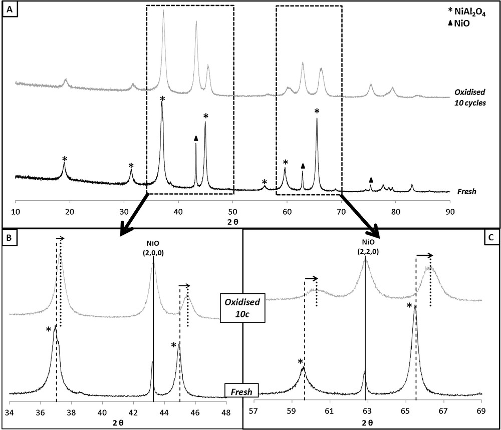
XRD pattern of the fresh and oxidised binder after 10 cycles (a) and enlargements of different parts of the pattern (b and c).
As shown in Table 2, it seems that during oxidation–reduction cycles, the peaks of nickel aluminate move towards those of pure γ-alumina (cubic phase: Fd-3m space group).
XRD peaks observed on the fresh binder and after 10 reduction/oxidation cycles, and reference peaks of nickel aluminate and γ-Al2O3 (data of literature).
| Fresh binder's peaks (2θ) | Peaks (2θ) (oxidised binder after 10 cycles) | NiAl2O4 ICDD PDF 01-081-0715 (Fd-3m cubic) | γ-Al2O3 ICDD PDF 00-050-0741 (Fd-3m cubic) |
| 19.0 | 19.3 | 19.086 | 19.348 |
| 31.4 | 31.7 | 31.416 | 31.855 |
| 37.0 | 37.3 | 37.020 | 37.539 |
| 45.0 | 45.5 | 45.026 | 45.668 |
| 59.6 | 60.3 | 59.654 | 60.546 |
| 65.5 | 66.3 | 65.568 | 66.602 |
These results may be explained by a structural evolution of the binder, which progressively decomposes, leading to the formation of γ-alumina and nickel oxide. The nickel oxide which is formed at high temperature is probably the species that reacts with the fuel and causes the increase in TC. To verify the increase in the amount of nickel oxide in the binder formed at high temperature by decomposition of NiAl2O4, the evolution of TC was studied during a new series of reduction–oxidation cycles on the fresh binder, at constant reduction parameters (T = 900 °C, [CO]inj = 0.55 vol.%, Q = 50 NL·h−1).
Fig. 10 represents the evolution of TC during reduction–oxidation cycles with constant reduction parameters (T = 900 °C, [CO]inj = 0.55 vol.%, Q = 50 NL·h−1) compared to the one obtained according to the procedure previously used for the study by DOE methodology (part 2.3). During reduction cycles at 900 °C, TC increases during the first cycles and becomes stable after the 5th or 6th cycle. The value of TC obtained after stabilization of the material corresponds to a high reactivity of the binder. Indeed at this level, 70% of the available oxygen in the binder oxidizes CO into CO2 during the reduction step. It is likely that a large part of NiAl2O4 gradually decomposes into NiO and alumina during the first cycles, and the NiO formed from decomposition of NiAl2O4 contributes to the activity of the material in oxidation of CO.
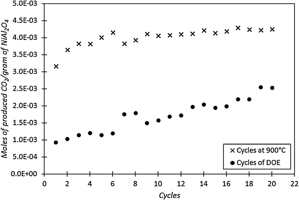
Evolution of TC during two series of cycles on the fresh binder: series 1: at 900 °C and series 2: according to DOE reduction conditions.
The amount of NiO present in the sample after the re-oxidation of the 20th cycle performed at 900 °C corresponds to 32 wt.% (calculated by integrating the CO2 curve), while in the fresh material, it was lower than 5 wt.%. Thus, taking into account these initial proportions, the final composition of the material after 20 cycles should be 32 wt.% of NiO, 33 wt.% of NiAl2O4 and 35 wt.% of γ-Al2O3.
The second curve shown in Fig. 10 presents the evolution of TC according to the cycles performed during the DOE experiments. As in previous tests, the TC of the binder increases gradually, but much more slowly than for experiments performed at 900 °C. Indeed, for the last cycles performed during the DOE experiments, TC corresponds to 46% of the available oxygen. This can be explained by the temperature of the reduction step, which was lower for experiments according to DOE methodology. The reduction conditions are very important for the binder activity modification. In the literature, some authors [32] have shown that pure γ-alumina is not the best binder for nickel oxide. Indeed, they observed a reaction between nickel oxide and γ-alumina to form nickel aluminate. So, all these results seem to indicate that nickel oxide, nickel aluminate and γ-alumina react more and less depending on the operating conditions.
4 Conclusion
The reactivity of the NiAl2O4 binder of a NiO/NiAl2O4 oxygen carrier has been studied in a fixed bed reactor. The results indicate that the binder can oxidize CO into CO2. The influence of the reduction parameters on the total reduction capacity of NiAl2O4 was studied by DOE methodology. It was observed that the total capacity increases with the reduction temperature. The evolution of the reactivity of the binder is probably due to structural modification of the material. XRD studies were performed on the binder and the results show a shift of the diffraction peaks of the nickel aluminate phase toward to those of γ-alumina phase. These observations can be attributed to the decomposition of the NiAl2O4 binder into γ-alumina and nickel oxide. This resulting metal oxide phase formed would be responsible for the activity of the binder in the oxidation of fuel (CO). These results show that nickel aluminate can no longer perform its binder function and could act on agglomeration phenomena by Ni metal migration.